EP1193203A1 - Vorrichtung zum Einfügen von flachen Produkten - Google Patents
Vorrichtung zum Einfügen von flachen Produkten Download PDFInfo
- Publication number
- EP1193203A1 EP1193203A1 EP01126551A EP01126551A EP1193203A1 EP 1193203 A1 EP1193203 A1 EP 1193203A1 EP 01126551 A EP01126551 A EP 01126551A EP 01126551 A EP01126551 A EP 01126551A EP 1193203 A1 EP1193203 A1 EP 1193203A1
- Authority
- EP
- European Patent Office
- Prior art keywords
- wall
- downstream
- conveyer
- pockets
- guiding element
- Prior art date
- Legal status (The legal status is an assumption and is not a legal conclusion. Google has not performed a legal analysis and makes no representation as to the accuracy of the status listed.)
- Granted
Links
Images


Classifications
-
- B—PERFORMING OPERATIONS; TRANSPORTING
- B65—CONVEYING; PACKING; STORING; HANDLING THIN OR FILAMENTARY MATERIAL
- B65H—HANDLING THIN OR FILAMENTARY MATERIAL, e.g. SHEETS, WEBS, CABLES
- B65H5/00—Feeding articles separated from piles; Feeding articles to machines
- B65H5/30—Opening devices for folded sheets or signatures
-
- B—PERFORMING OPERATIONS; TRANSPORTING
- B65—CONVEYING; PACKING; STORING; HANDLING THIN OR FILAMENTARY MATERIAL
- B65H—HANDLING THIN OR FILAMENTARY MATERIAL, e.g. SHEETS, WEBS, CABLES
- B65H39/00—Associating, collating, or gathering articles or webs
- B65H39/02—Associating,collating or gathering articles from several sources
- B65H39/04—Associating,collating or gathering articles from several sources from piles
- B65H39/043—Associating,collating or gathering articles from several sources from piles the piles being disposed in juxtaposed carriers
-
- B—PERFORMING OPERATIONS; TRANSPORTING
- B65—CONVEYING; PACKING; STORING; HANDLING THIN OR FILAMENTARY MATERIAL
- B65H—HANDLING THIN OR FILAMENTARY MATERIAL, e.g. SHEETS, WEBS, CABLES
- B65H2301/00—Handling processes for sheets or webs
- B65H2301/40—Type of handling process
- B65H2301/43—Gathering; Associating; Assembling
- B65H2301/431—Features with regard to the collection, nature, sequence and/or the making thereof
- B65H2301/4317—Signatures, i.e. involving folded main product or jacket
- B65H2301/43171—Inserting subproducts in a signature as main product
- B65H2301/431711—Inserting subproducts in a signature as main product the subproduct being inserted in a direction substantially perpendicular to the fold of the main product
-
- B—PERFORMING OPERATIONS; TRANSPORTING
- B65—CONVEYING; PACKING; STORING; HANDLING THIN OR FILAMENTARY MATERIAL
- B65H—HANDLING THIN OR FILAMENTARY MATERIAL, e.g. SHEETS, WEBS, CABLES
- B65H2301/00—Handling processes for sheets or webs
- B65H2301/40—Type of handling process
- B65H2301/43—Gathering; Associating; Assembling
- B65H2301/432—Gathering; Associating; Assembling in pockets, i.e. vertically
-
- B—PERFORMING OPERATIONS; TRANSPORTING
- B65—CONVEYING; PACKING; STORING; HANDLING THIN OR FILAMENTARY MATERIAL
- B65H—HANDLING THIN OR FILAMENTARY MATERIAL, e.g. SHEETS, WEBS, CABLES
- B65H2301/00—Handling processes for sheets or webs
- B65H2301/40—Type of handling process
- B65H2301/43—Gathering; Associating; Assembling
- B65H2301/437—Repairing a faulty collection due to, e.g. misfeed, multiplefeed
-
- B—PERFORMING OPERATIONS; TRANSPORTING
- B65—CONVEYING; PACKING; STORING; HANDLING THIN OR FILAMENTARY MATERIAL
- B65H—HANDLING THIN OR FILAMENTARY MATERIAL, e.g. SHEETS, WEBS, CABLES
- B65H2406/00—Means using fluid
- B65H2406/30—Suction means
-
- B—PERFORMING OPERATIONS; TRANSPORTING
- B65—CONVEYING; PACKING; STORING; HANDLING THIN OR FILAMENTARY MATERIAL
- B65H—HANDLING THIN OR FILAMENTARY MATERIAL, e.g. SHEETS, WEBS, CABLES
- B65H2406/00—Means using fluid
- B65H2406/30—Suction means
- B65H2406/35—Other elements with suction surface, e.g. plate or wall
- B65H2406/351—Other elements with suction surface, e.g. plate or wall facing the surface of the handled material
-
- B—PERFORMING OPERATIONS; TRANSPORTING
- B65—CONVEYING; PACKING; STORING; HANDLING THIN OR FILAMENTARY MATERIAL
- B65H—HANDLING THIN OR FILAMENTARY MATERIAL, e.g. SHEETS, WEBS, CABLES
- B65H2406/00—Means using fluid
- B65H2406/30—Suction means
- B65H2406/36—Means for producing, distributing or controlling suction
- B65H2406/361—Means for producing, distributing or controlling suction distributing vacuum from stationary element to movable element
Definitions
- the present Invention is directed to devices which enable the insertion of substantially flat inserts into openable products located in moving pockets, as well as improvements in the pockets themselves.
- the Invention will be specifically described with regard to transportation of newspaper jackets and insertion of various supplemental materials therein, but is not intended to be limited thereto. It is particularly useful in connection with flat products, especially those which are incapable of supporting their own weight.
- Devices for introducing supplements into outer sections of newspapers have been known for many years. Generally, they comprise a plurality of pockets mounted on a chain movable in a closed path. An outer section or jacket is introduced into each of the pockets, usually with the folded edge adjacent the hinge. The pocket is then closed, the edges of the paper remote from the hinge are held to the inner faces of the pocket, and the pocket is thereafter opened. As a result, the pocket now contains the jacket in opened position, ready to receive the inserts. As the pockets move in a closed path, part of which carries them adjacent devices which feed the inserts into the jackets, they are then transported to the next step in the handling thereof.
- the present Invention comprises a device for transferring a plurality of flat products (i.e. newspaper jackets and/or inserts therefor) individually into a plurality of pockets attached to - and spaced apart along - an endless conveyor moving in a closed path in a downstream direction.
- Each of the pockets includes a downstream wall, having an upper edge and a lower edge parallel thereto, and an upstream wall, (which may be connected by a hinge to the downstream wall adjacent the lower edge); the walls are capable of movement between an open position, wherein they are spaced apart, and a closed position, wherein they are adjacent to or bear against each other.
- Each of the pockets is attached to a conveyor, preferably at both sides thereof and at points intermediate their lower edge and the upper edge'. The pockets are oriented so that, during one flight of the conveyor, each lower edge is below its corresponding upper edge.
- the Invention will be primarily described in connection with pockets wherein the walls are hinged to each other at their lower ends.
- the description will focus on pockets wherein the upstream wall is movable and the downstream wall is fixed.
- these are not limitations on the Invention, but rather that it is broad enough to encompass pockets wherein the walls are not hinged to each other, and in which either or both of the walls are movable.
- the conveyor passes around a rotatable member at extremities of the path.
- the rotatable members have diameters which are greater than the distance between adjacent flights of the conveyor, so that the lower edges do not contact each other as the conveyor passes around the rotatable members.
- the conveyor has raised ends and a lowered central portion. Since the operators place the inserts in the feed hoppers along the central portion, it is of advantage to keep the center low so as to facilitate this operation.
- At least one wall carries an actuator bar which is substantially parallel to the hinge; the bar is slidably mounted thereon so that it can move in a direction substantially perpendicular to the hinge.
- the wall is biased toward one of its two positions, preferably toward the closed position.
- the bar is mounted loosely in its bracket.
- the wall is permitted substantial flexibility to accommodate outer sections into which the inserts have been unevenly introduced.
- each of the pockets carries a first pair of bushings, one on each side thereof.
- the bushings are adapted for connection to complementary bushings on the following pocket.
- the preceding pocket has bushings which are connected to the first pocket, thereby coupling the pockets together along the path of the conveyor.
- rollers which support the pockets and also cooperate with the sprockets at the ends of the path to drive the conveyor. Specifically, the rollers fit into notches on the sprocket.
- the sprocket is also provided with a plurality of opening cams, one for each notch.
- the opening cams cooperating with cam followers on the pockets, cause the pockets to open and remain open during the travel of the pocket around the sprocket.
- a further stationary cam is provided as the pockets exit the sprockets to prevent sudden closing thereof. As a result, the pockets are first opened, then emptied, and then allowed to close slowly to avoid damage.
- MIRS Missed Insert Repair Systems
- the opening cam contacts the cam follower to open the pocket in the normal way.
- the opening cam is moved into another position wherein it does not contact the cam follower.
- this pocket is not opened and the portion of the paper contained therein remains so that a suitable repair can be made.
- the edges of the jackets are secured to the inner surfaces of the walls by the application of vacuum thereto.
- a stationary plenum which is adjacent one side of the openable pockets.
- Each pocket is provided with a suction cup connected to vacuum tubes which terminate at the face of one of the walls thereof, preferably the fixed downstream wall.
- An endless belt which passes around rotatable idlers at its extremities, is located so that one flight thereof is between the plenum and the pockets.
- Vacuum holes are provided on the belt, spaced apart at a distance corresponding to the distance between successive vacuum cups on the pockets.
- the belt also has notches or teeth and the pockets are adapted to engage the belt at the notches or teeth, thereby driving it. In this manner, the vacuum in the plenum is transferred to the pockets. Since the pockets themselves drive the belt, proper timing is insured without the necessity of expensive or complicated mechanisms.
- the belt may carry vacuum transmitting elements which bear against - and are complementary to - the vacuum inlets on the corresponding pockets. Protuberances can be provided on the belt which are engaged by the pockets.
- Another embodiment is directed to the provision of a pair of flexible - preferably leaf - springs on the upstream wall. These springs urge the paper, when in the pocket, toward the downstream wall and away from the upstream wall. They are located near the fold so that they do not interfere with the opening of the jacket. Alternatively, the springs can be mounted on the downstream wall and urge the jacket toward the upstream wall.
- the springs provide a further advantage.
- the jackets are inserted into the pockets at a very rapid rate. As a result, there is a tendency for them to rebound when they hit the bottom of the pocket.
- the presence of the springs cushions the stop and aids in preventing the paper from becoming misaligned due to the speed at which it is introduced.
- the pockets have a spring (advantageously a compression spring), with a fixed end mounted on the outer surface of the downstream wall.
- the spring extends, from the fixed end, parallel to the outer surface, toward the lower edge thereof, and terminates in a movable end.
- a lever pivotally mounted on the downstream wall at a pivot point, which has an actuated arm extending from the pivot point with a distal end in contact with the movable end of the spring.
- the lever also has a receiving arm extending from the pivot point toward the upstream wall and terminating at a pressure end, the pressure end being in contact with the upstream wall.
- This receiving arm is connected to an actuator bar which is loosely mounted on the upstream wall.
- the bar extends substantially parallel to the hinge and is retained in a bracket which is elongated in the direction perpendicular to the hinge.
- the actuator bar bears against the upstream wall and presses it firmly against the downstream wall.
- the actuator bar presses against the underside of the portion of the bracket which is parallel to the upstream wall. Since the actuator bar is loosely mounted therein, the upstream wall is no longer rigidly secured. As a result, it can flex to accommodate uneven inserts, when in the closed position.
- the compression spring may be mounted on the upstream wall or there may be compression springs on both walls.
- a further problem may arise which is also solved by a feature of the present Invention.
- a pair of jacket feeders is provided, each operating at half speed and feeding alternate pockets.
- the jackets fed thereby may not fully enter the opened pocket as it passes beneath the feeder.
- the trailing portion of the jacket may fall over the upper edge of the upstream wall in the upstream direction. This prevents the jacket from sliding entirely into the pocket and may also interfere with the introduction of the jacket into the following pocket by the adjacent feeder.
- the pockets are provided with a device which causes the jacket to assume an arcuate configuration which is concave in the upstream direction.
- the jacket is stiffened and its tendency to fold over the upper edge of the upstream wall is minimized. This facilitates its slide into the pocket to reach the bottom thereof.
- the upstream wall of each pocket when in the open position, is adjacent the downstream wall of the pocket immediately upstream thereof.
- the device for causing the arcuate formation is on the downstream side of the downstream wall of the upstream pocket.
- the downstream wall may have a V-notch or protuberances thereon to cause the desired shape to be formed.
- a further possibility is the use of an arcuate shape of the wall to achieve the same result.
- the present Invention is not limited to any particular means for forming this shape, as alternatives to the foregoing will readily suggest themselves to the person of ordinary skill.
- the shape be concave in the downstream direction (convex in the upstream direction), it is entirely feasible to accomplish the reverse, i.e. the shape can be convex in the downstream direction (concave in the upstream direction).
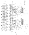
- Transfer device 1 comprises feeders 2 and conveyor 3.
- Conveyor 3 forms outgoing flight 4, wherein pockets 11 are prepared to receive a product from stack 6.
- Singulator 47 feeds one product 7 to gripper 48 which carries it around feed wheel 8.
- Jacket 7, as shown in the left feeder 2 of Figure 1, is then dropped into one of pockets 11.
- hinges 19 approach each other very closely as the conveyor travels around pairs of sprocket wheels at the extremities of the path. In order to permit this, enlarged diameter section 12 is provided at these points. This enables hinges 9 to clear one another during this portion of the travel and still allow flights 4 and 5 to be relatively close to each other. It provides an added advantage whereby flight 4 can be located at a convenient height for the operator(s).
- the idler end of conveyor 3 may comprise sprocket wheels analogous to those shown in Figure 2. However, it has been found advantageous to use the construction of Figure 14. As can be seen therein, enlarged diameter section 12 is shown within frame 73. Idler cams 74 are provided and rollers 37 roll thereover. This eliminates the necessity for a second pair of sprocket wheels.
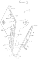
- pocket 11 The construction of pocket 11 is best shown in Figure 3. It comprises fixed wall 13 having upper edge 17 and lower edge 18. Movable wall 14 includes far edge 15 and near edge 16. Fixed wall 13 and movable wall 14 are connected at hinge 19 adjacent near edge 16 and lower edge 18. Fixed wall 13 has upper portion 21 which is at an angle to lower portion 22. On outer surface 23 is mounted compression spring 25 extending between fixed end 24 and movable end 26. Actuated arm 27 connects movable end 26 with pivot 28. On the other side of pivot 28 is receiving arm 29 which engages actuator bar 30. Exterior surface 20 of movable wall 14 carries bracket 31 in which bar 30 is slidable.
- the pockets are shown in open and closed position, respectively.
- Actuator bar 30 is loosely mounted in bracket 31, thus forming gap 79.
- the loose fit permits movable wall 14 to assume positions which are not parallel to fixed wall 13 when in the closed position.
- thick end 56 can be accommodated without risk of damaging movable wall 14 or allowing the inserts to slip out.
- the pressure of spring 25 on movable end 26 urges actuated arm 27 in the downward direction as shown in Figure 3. This force is transmitted through pivot 28 to receiving arm 29 and causes bar 30 to move upwardly in bracket 31, thereby bringing movable wall 14 to its closed position.
- Center pocket 11 has following bushings 33 which engage following pocket 36; similarly, preceding bushings 34 engage preceding pocket 35.
- Rollers 37 and 38 support plurality 32 and the pockets.
- vacuum inlets 39 are provided in upper portion 21 of the pockets.
- Linked plurality 32 of pockets 11 is shown in perspective in Figure 15. It is a feature of one embodiment of the present Invention that fixed wall 13 is provided with chamfers 80. As jacket 7 is inserted into pocket 11, the force of movement in the downstream direction of arrow 77, together with the configuration of the device, (especially chamfers 80), causes jacket 7 to bow at 76 in the upstream direction . This curved shape tends to stiffen jacket 7 and prevent upper end 78, which extends beyond upper portion 21 of pocket 11, from folding over the outer surface of upper portion 21.
- downstream wall 13 and/or upstream wall 14 may be arcuate in shape, bowing upstream in the direction opposite to arrow 77.
- chamfers 80 can be a V-shape, which would achieve substantially the same result. Even protuberances extending downstream from the downstream face of fixed wall 13 will provide the bowing effect.
- FIG. 15 shows the elements for causing bowing at 76 on fixed wall 13, this is not essential.
- Movable wall 14 can carry similar devices to accomplish the same result. In the latter case, however, it is more advantageous if there is a space between movable wall 14 of one pocket 11 and fixed wall 13 of the immediately upstream pocket 11 when the pocket is in its open position.
- sprocket 50 In order to be certain that the pockets are empty of any residual papers or inserts at the end of the insertion cycle, the sprocket is provided with a particular mechanism for doing so.
- sprocket 50 carries notches 52 into which support rollers 40 of pockets 11 fit.
- cam followers 53 bear against opening cams 51.
- Locking support roller 81 enters notch 52; thereafter, trailing support roller 82 enters the next notch 52.
- cam follower 53 to bear against cam 51, thus opening the pocket, the rotation of sprocket 50 inverts the open pocket.
- pockets 11 are emptied by a combination of centrifugal force and gravity.
- stationary cam 54 In order to prevent pockets 11 from snapping shut violently, and hence risking damage thereto, stationary cam 54 bears against cam followers 53 and guides them so that closure of pockets 11 is accomplished slowly.
- Missed Insert Repair System is being used.
- this system senses that an insert has been missed, it disables the gripper opening cam so that the paper will go through a second cycle to pick up the missing insert.
- all of the inserting stations subsequent to the one which was missed are also disabled. Thereafter, when the paper is returned to the original missed station, all of the subsequent stations are enabled.
- the specific pocket to be recycled must not be opened and emptied when traveling around sprocket 50. This is accomplished by moving the selected opening cam 51 which corresponds to the missed insert pocket in a direction perpendicular to the plane of sprocket 50. Opening cam 51 becomes inoperative cam 55 as shown in dotted lines in Figure 11. In this position, the cam does not contact cam follower 53 and the specific pocket is not opened.
- Plenum 41 is located within the path of vacuum belt 42. Upper portions 21 are equipped with suction inlets 43 which are in communication with vacuum inlets 39. On belt 42 are vacuum holes 72. Idlers 46 permit belt 42 to be driven by pockets 11. In operation, teeth 45 mounted on pockets 11 engage notches 70 on belt 42. As pockets 11 are driven, belt 42 is carried along therewith. Since plenum 41 is under vacuum, this vacuum is communicated through vacuum holes 72, vacuum cups 44, suction inlets 43, and vacuum tubes 71 to vacuum inlets 39. Plenum 41 is proportioned with regard to the cycle of pockets 11 so that vacuum is applied thereto only when required.
- each pocket 11 carries side opener 57 which is attached thereto by brackets 59.
- Rod 58 is slidably mounted therein for movement in either direction as indicated by arrow 60.
- Divider 61 is adapted for movement in the directions indicated by arrow 62.
- Adjustment cam follower 65 is connected to link 64 through pin 63. As adjustment cam follower 65 is urged inward, link 64, and divider 61, are moved toward the lower left. When adjustment cam follower 65 moves outwardly, link 64 and divider 61 move toward the upper right. Since adjustment cam follower 65 is spring biased outwardly, and adjustment cam 66 can be set at various positions in the directions of arrow 69, the precise point at which divider 61 will enter the paper can easily be set. Moreover, since the setting is only of stationary cam 66, this can be accomplished without stopping the operation of the machine.
Priority Applications (2)
| Application Number | Priority Date | Filing Date | Title |
|---|---|---|---|
| DE1996631300 DE69631300T2 (de) | 1996-09-30 | 1996-09-30 | Vorrichtung zum Einfügen von flachen Produkten |
| AT01126551T ATE257456T1 (de) | 1996-09-30 | 1996-09-30 | Vorrichtung zum einfügen von flachen produkten |
Applications Claiming Priority (2)
| Application Number | Priority Date | Filing Date | Title |
|---|---|---|---|
| US08/401,425 US5823320A (en) | 1995-03-09 | 1995-03-09 | Inserter for flat products |
| EP96115630A EP0881184B1 (de) | 1995-03-09 | 1996-09-30 | Vorrichtung zum Einfügen von flachen Produkten |
Related Parent Applications (1)
| Application Number | Title | Priority Date | Filing Date |
|---|---|---|---|
| EP96115630A Division EP0881184B1 (de) | 1995-03-09 | 1996-09-30 | Vorrichtung zum Einfügen von flachen Produkten |
Publications (2)
| Publication Number | Publication Date |
|---|---|
| EP1193203A1 true EP1193203A1 (de) | 2002-04-03 |
| EP1193203B1 EP1193203B1 (de) | 2004-01-07 |
Family
ID=26142202
Family Applications (3)
| Application Number | Title | Priority Date | Filing Date |
|---|---|---|---|
| EP96115630A Expired - Lifetime EP0881184B1 (de) | 1995-03-09 | 1996-09-30 | Vorrichtung zum Einfügen von flachen Produkten |
| EP01126550A Expired - Lifetime EP1193202B1 (de) | 1995-03-09 | 1996-09-30 | Vorrichtung zum Einfügen von flachen Produkten |
| EP01126551A Expired - Lifetime EP1193203B1 (de) | 1995-03-09 | 1996-09-30 | Vorrichtung zum Einfügen von flachen Produkten |
Family Applications Before (2)
| Application Number | Title | Priority Date | Filing Date |
|---|---|---|---|
| EP96115630A Expired - Lifetime EP0881184B1 (de) | 1995-03-09 | 1996-09-30 | Vorrichtung zum Einfügen von flachen Produkten |
| EP01126550A Expired - Lifetime EP1193202B1 (de) | 1995-03-09 | 1996-09-30 | Vorrichtung zum Einfügen von flachen Produkten |
Country Status (5)
| Country | Link |
|---|---|
| US (1) | US5823320A (de) |
| EP (3) | EP0881184B1 (de) |
| AT (1) | ATE220383T1 (de) |
| DE (1) | DE69622284T2 (de) |
| DK (3) | DK1193203T3 (de) |
Families Citing this family (16)
| Publication number | Priority date | Publication date | Assignee | Title |
|---|---|---|---|---|
| US5868239A (en) | 1997-01-27 | 1999-02-09 | United Parcel Service Of America, Inc. | Conveyor including controlled package ejection capabilities |
| CH696637A5 (de) * | 1997-01-31 | 2007-08-31 | Ferag Ag | Verfahren zum Einstecken von Druckprodukten in ein gefaltetes Hauptprodukt. |
| US5950798A (en) * | 1997-02-26 | 1999-09-14 | United Parcel Services Of America | Air distribution systems for shoe sorter |
| US6170638B1 (en) * | 1999-05-07 | 2001-01-09 | Graphic Management Associates, Inc. | Stream aligner |
| DK174642B1 (da) * | 2001-03-23 | 2003-08-04 | Schur Packaging Systems As | Fremgangsmåde og indretning til åbning af to sæt sammenlagte materialestykker samt arrangement omfattende et antal sådanne indrtninger |
| CA2408879C (en) | 2001-10-19 | 2006-07-25 | Bell & Howell Mail And Messaging Technologies Company | Apparatus and method for stuffing a folder |
| WO2004000503A2 (en) * | 2002-06-20 | 2003-12-31 | Graphic Management Associates, Inc. | Insert machine |
| US6695306B2 (en) * | 2002-06-24 | 2004-02-24 | Heidelberger Druckmaschinen Ag | Sheet material conveying apparatus with height-adjustable pockets |
| US7284750B2 (en) * | 2003-10-16 | 2007-10-23 | Dwayne Glowner | Method and apparatus for handling inserts for printed materials |
| US8631928B2 (en) * | 2003-12-15 | 2014-01-21 | Goss International Americas, Inc. | Conveyor for printed sheet material with air assisted drop |
| DK1780155T3 (da) | 2004-10-14 | 2012-01-23 | Muller Martini Mailroom Systems Inc | Produkttilførselsapparat med accelerator- og decelerationsindretninger |
| EP1946939B8 (de) * | 2007-01-19 | 2012-02-29 | Muller Martini Corp. | Zuführung für dicke Produkte |
| US8695313B2 (en) * | 2008-12-04 | 2014-04-15 | Lockheed Martin Corporation | Method of inserting mail pieces into individual folder |
| EP2551224B1 (de) * | 2011-07-29 | 2014-03-12 | Müller Martini Holding AG | Verfahren zum Betrieb einer Sammeleinrichtung für Druckprodukte |
| US8434752B2 (en) * | 2011-08-05 | 2013-05-07 | Goss International Americas, Inc. | Apparatus for opening and transporting a product with a non-symmetrical fold |
| CH708427A1 (de) * | 2013-08-12 | 2015-02-13 | Ferag Ag | Vorrichtung und Verfahren zum Separieren von Produktteilen eines mehrteiligen Produktes. |
Citations (4)
| Publication number | Priority date | Publication date | Assignee | Title |
|---|---|---|---|---|
| DE516168C (de) * | 1928-03-21 | 1931-01-24 | Burgerhout S Machf & Scheepswe | Beilageneinsteckmaschine |
| WO1987007881A1 (en) * | 1986-06-20 | 1987-12-30 | Graphic Management Associates, Inc. | Straight-line insert machine |
| EP0476859A2 (de) * | 1990-08-27 | 1992-03-25 | Graphic Management Associates, Inc. | Einrichtung zum öffnen von gefalteten Druckereierzeugnissen |
| EP0498935A1 (de) * | 1991-02-13 | 1992-08-19 | Graphic Management Associates, Inc. | Vorrichtung zum Öffnen |
Family Cites Families (8)
| Publication number | Priority date | Publication date | Assignee | Title |
|---|---|---|---|---|
| US4373710A (en) * | 1980-08-22 | 1983-02-15 | Nolan Systems, Inc. | Apparatus for inserting supplementary material into newspaper jackets |
| DE3107458A1 (de) * | 1981-02-27 | 1982-09-16 | Rahdener Maschinenfabrik August Kolbus Gmbh & Co Kg, 4993 Rahden | Buchblockzange fuer transportsystem |
| US4723770A (en) * | 1986-06-20 | 1988-02-09 | Graphic Management Associates, Inc. | Straight-line insert machine |
| US4921294A (en) * | 1988-06-03 | 1990-05-01 | Am International Incorporated | Spring wire gripper jaw |
| US4988086A (en) * | 1989-01-26 | 1991-01-29 | Am International Incorporated | Apparatus and method for forming sheet material assemblages |
| CH677652A5 (de) * | 1989-03-07 | 1991-06-14 | Grapha Holding Ag | |
| JP3342097B2 (ja) * | 1992-06-01 | 2002-11-05 | グラプハ−ホルディング・アクチエンゲゼルシヤフト | 差込み機械 |
| US5450939A (en) * | 1993-11-30 | 1995-09-19 | Eastman Kodak Company | Apparatus and method for transferring objects |
-
1995
- 1995-03-09 US US08/401,425 patent/US5823320A/en not_active Expired - Lifetime
-
1996
- 1996-09-30 DK DK01126551T patent/DK1193203T3/da active
- 1996-09-30 AT AT96115630T patent/ATE220383T1/de active
- 1996-09-30 EP EP96115630A patent/EP0881184B1/de not_active Expired - Lifetime
- 1996-09-30 EP EP01126550A patent/EP1193202B1/de not_active Expired - Lifetime
- 1996-09-30 DK DK96115630T patent/DK0881184T3/da active
- 1996-09-30 EP EP01126551A patent/EP1193203B1/de not_active Expired - Lifetime
- 1996-09-30 DE DE69622284T patent/DE69622284T2/de not_active Expired - Lifetime
- 1996-09-30 DK DK01126550T patent/DK1193202T3/da active
Patent Citations (4)
| Publication number | Priority date | Publication date | Assignee | Title |
|---|---|---|---|---|
| DE516168C (de) * | 1928-03-21 | 1931-01-24 | Burgerhout S Machf & Scheepswe | Beilageneinsteckmaschine |
| WO1987007881A1 (en) * | 1986-06-20 | 1987-12-30 | Graphic Management Associates, Inc. | Straight-line insert machine |
| EP0476859A2 (de) * | 1990-08-27 | 1992-03-25 | Graphic Management Associates, Inc. | Einrichtung zum öffnen von gefalteten Druckereierzeugnissen |
| EP0498935A1 (de) * | 1991-02-13 | 1992-08-19 | Graphic Management Associates, Inc. | Vorrichtung zum Öffnen |
Also Published As
| Publication number | Publication date |
|---|---|
| EP1193202A1 (de) | 2002-04-03 |
| DK0881184T3 (da) | 2002-11-04 |
| EP0881184B1 (de) | 2002-07-10 |
| DK1193203T3 (da) | 2004-05-17 |
| DE69622284D1 (de) | 2002-08-14 |
| ATE220383T1 (de) | 2002-07-15 |
| EP0881184A1 (de) | 1998-12-02 |
| DK1193202T3 (da) | 2004-04-05 |
| DE69622284T2 (de) | 2003-03-27 |
| US5823320A (en) | 1998-10-20 |
| EP1193203B1 (de) | 2004-01-07 |
| EP1193202B1 (de) | 2003-11-26 |
Similar Documents
| Publication | Publication Date | Title |
|---|---|---|
| EP1193202B1 (de) | Vorrichtung zum Einfügen von flachen Produkten | |
| US5104108A (en) | Apparatus for collecting, assembling and inserting printery products | |
| US4723770A (en) | Straight-line insert machine | |
| KR100444887B1 (ko) | 멀티팩포장장치 | |
| US4133521A (en) | Sheet material collating apparatus | |
| FI83413C (fi) | Anordning foer sammanfoerande av olika slags tryckprodukter. | |
| CA1264167A (en) | Method and apparatus for opening printed products which have been folded off-center | |
| CA2086633C (en) | System for bottom feeding and discharging imbricated material to/from an intermediate stack | |
| US5292111A (en) | Method and apparatus for opening folded printed products having distinct sheet opening and hold-open means | |
| JP3057536B2 (ja) | 印刷物の加工方法および装置 | |
| CN1081591C (zh) | 向使用设备传送坯件的方法和装置 | |
| AU764208B2 (en) | Apparatus for transporting flexible, sheet-like products away and/or further | |
| GB2114957A (en) | Method of, and apparatus for, processing two product formations, each formed by substantially flat products, especially printed products | |
| US4678174A (en) | Apparatus for picking-up and further transporting, folded printed products, especially signatures or sheets, from a conveying device | |
| GB2134891A (en) | Apparatus for manipulating stacks of paper sheets or the like | |
| EP0270663B1 (de) | Einsteckmaschine in gerader linie | |
| US4767112A (en) | Folded copy product transfer and transport apparatus | |
| EP1052208B1 (de) | Taschenförderer mit Produktausrichter | |
| JP5380129B2 (ja) | 印刷製品の次処理をするための丁合い区間内の搬送装置 | |
| CA1086342A (en) | Sheet feeding device | |
| GB1562281A (en) | Valved bag feeding and opening device of apparatus for engaging empty valved bags onto filling nozzles of a rotary babbing machine | |
| US20130032987A1 (en) | Apparatus for opening and transporting a product with a non-symetrical fold | |
| US4641829A (en) | Screen printing machine having a stationary printing table | |
| US5819909A (en) | Apparatus for receiving and transporting flat articles | |
| JPH10157901A (ja) | 平坦な製品の差込装置 |
Legal Events
| Date | Code | Title | Description |
|---|---|---|---|
| PUAI | Public reference made under article 153(3) epc to a published international application that has entered the european phase |
Free format text: ORIGINAL CODE: 0009012 |
|
| AC | Divisional application: reference to earlier application |
Ref document number: 881184 Country of ref document: EP |
|
| AK | Designated contracting states |
Kind code of ref document: A1 Designated state(s): AT CH DE DK GB LI SE |
|
| RIN1 | Information on inventor provided before grant (corrected) |
Inventor name: HONEGGER, ROGER C/O GRAPHIC MANAGEMENT ASSOCIATES Inventor name: SILVA, ROBERT M. Inventor name: DAVENPORT, GARY L. Inventor name: COHEN, NEAL B. Inventor name: BUSH, LAWRENCE Inventor name: SEIDEL, RANDY R. |
|
| 17P | Request for examination filed |
Effective date: 20020831 |
|
| AKX | Designation fees paid |
Free format text: AT CH DE DK GB LI SE |
|
| GRAH | Despatch of communication of intention to grant a patent |
Free format text: ORIGINAL CODE: EPIDOS IGRA |
|
| GRAS | Grant fee paid |
Free format text: ORIGINAL CODE: EPIDOSNIGR3 |
|
| GRAA | (expected) grant |
Free format text: ORIGINAL CODE: 0009210 |
|
| AC | Divisional application: reference to earlier application |
Ref document number: 0881184 Country of ref document: EP Kind code of ref document: P |
|
| AK | Designated contracting states |
Kind code of ref document: B1 Designated state(s): AT CH DE DK GB LI SE |
|
| REG | Reference to a national code |
Ref country code: GB Ref legal event code: FG4D |
|
| REG | Reference to a national code |
Ref country code: CH Ref legal event code: EP |
|
| REF | Corresponds to: |
Ref document number: 69631300 Country of ref document: DE Date of ref document: 20040212 Kind code of ref document: P |
|
| REG | Reference to a national code |
Ref country code: SE Ref legal event code: TRGR |
|
| REG | Reference to a national code |
Ref country code: CH Ref legal event code: NV Representative=s name: LUCHS & PARTNER PATENTANWAELTE |
|
| REG | Reference to a national code |
Ref country code: DK Ref legal event code: T3 |
|
| PLBE | No opposition filed within time limit |
Free format text: ORIGINAL CODE: 0009261 |
|
| STAA | Information on the status of an ep patent application or granted ep patent |
Free format text: STATUS: NO OPPOSITION FILED WITHIN TIME LIMIT |
|
| 26N | No opposition filed |
Effective date: 20041008 |
|
| PGFP | Annual fee paid to national office [announced via postgrant information from national office to epo] |
Ref country code: AT Payment date: 20100901 Year of fee payment: 15 |
|
| PGFP | Annual fee paid to national office [announced via postgrant information from national office to epo] |
Ref country code: GB Payment date: 20100927 Year of fee payment: 15 |
|
| PGFP | Annual fee paid to national office [announced via postgrant information from national office to epo] |
Ref country code: CH Payment date: 20110922 Year of fee payment: 16 Ref country code: DK Payment date: 20110921 Year of fee payment: 16 |
|
| PGFP | Annual fee paid to national office [announced via postgrant information from national office to epo] |
Ref country code: DE Payment date: 20110915 Year of fee payment: 16 Ref country code: SE Payment date: 20110920 Year of fee payment: 16 |
|
| GBPC | Gb: european patent ceased through non-payment of renewal fee |
Effective date: 20110930 |
|
| PG25 | Lapsed in a contracting state [announced via postgrant information from national office to epo] |
Ref country code: GB Free format text: LAPSE BECAUSE OF NON-PAYMENT OF DUE FEES Effective date: 20110930 |
|
| REG | Reference to a national code |
Ref country code: AT Ref legal event code: MM01 Ref document number: 257456 Country of ref document: AT Kind code of ref document: T Effective date: 20110930 |
|
| PG25 | Lapsed in a contracting state [announced via postgrant information from national office to epo] |
Ref country code: AT Free format text: LAPSE BECAUSE OF NON-PAYMENT OF DUE FEES Effective date: 20110930 |
|
| REG | Reference to a national code |
Ref country code: CH Ref legal event code: PL |
|
| REG | Reference to a national code |
Ref country code: DK Ref legal event code: EBP |
|
| PG25 | Lapsed in a contracting state [announced via postgrant information from national office to epo] |
Ref country code: SE Free format text: LAPSE BECAUSE OF NON-PAYMENT OF DUE FEES Effective date: 20121001 Ref country code: DE Free format text: LAPSE BECAUSE OF NON-PAYMENT OF DUE FEES Effective date: 20130403 Ref country code: LI Free format text: LAPSE BECAUSE OF NON-PAYMENT OF DUE FEES Effective date: 20120930 Ref country code: CH Free format text: LAPSE BECAUSE OF NON-PAYMENT OF DUE FEES Effective date: 20120930 |
|
| REG | Reference to a national code |
Ref country code: DE Ref legal event code: R119 Ref document number: 69631300 Country of ref document: DE Effective date: 20130403 |
|
| PG25 | Lapsed in a contracting state [announced via postgrant information from national office to epo] |
Ref country code: DK Free format text: LAPSE BECAUSE OF NON-PAYMENT OF DUE FEES Effective date: 20121001 |