EP1193090A2 - Anschlagpuffer - Google Patents
Anschlagpuffer Download PDFInfo
- Publication number
- EP1193090A2 EP1193090A2 EP01121123A EP01121123A EP1193090A2 EP 1193090 A2 EP1193090 A2 EP 1193090A2 EP 01121123 A EP01121123 A EP 01121123A EP 01121123 A EP01121123 A EP 01121123A EP 1193090 A2 EP1193090 A2 EP 1193090A2
- Authority
- EP
- European Patent Office
- Prior art keywords
- buffer
- components
- component
- buffer part
- stop
- Prior art date
- Legal status (The legal status is an assumption and is not a legal conclusion. Google has not performed a legal analysis and makes no representation as to the accuracy of the status listed.)
- Granted
Links
- 239000000872 buffer Substances 0.000 title claims description 232
- 238000000034 method Methods 0.000 claims abstract description 20
- 239000000853 adhesive Substances 0.000 claims description 7
- 230000001070 adhesive effect Effects 0.000 claims description 7
- 238000000926 separation method Methods 0.000 claims description 4
- 239000012790 adhesive layer Substances 0.000 claims 1
- 239000006096 absorbing agent Substances 0.000 abstract 4
- 230000035939 shock Effects 0.000 abstract 4
- 230000003993 interaction Effects 0.000 description 3
- 239000003292 glue Substances 0.000 description 2
- 239000002184 metal Substances 0.000 description 2
- 238000009434 installation Methods 0.000 description 1
- 239000000463 material Substances 0.000 description 1
- 238000010422 painting Methods 0.000 description 1
- 230000008092 positive effect Effects 0.000 description 1
- 230000036316 preload Effects 0.000 description 1
- 238000009420 retrofitting Methods 0.000 description 1
Images

Classifications
-
- F—MECHANICAL ENGINEERING; LIGHTING; HEATING; WEAPONS; BLASTING
- F16—ENGINEERING ELEMENTS AND UNITS; GENERAL MEASURES FOR PRODUCING AND MAINTAINING EFFECTIVE FUNCTIONING OF MACHINES OR INSTALLATIONS; THERMAL INSULATION IN GENERAL
- F16F—SPRINGS; SHOCK-ABSORBERS; MEANS FOR DAMPING VIBRATION
- F16F15/00—Suppression of vibrations in systems; Means or arrangements for avoiding or reducing out-of-balance forces, e.g. due to motion
- F16F15/02—Suppression of vibrations of non-rotating, e.g. reciprocating systems; Suppression of vibrations of rotating systems by use of members not moving with the rotating systems
- F16F15/04—Suppression of vibrations of non-rotating, e.g. reciprocating systems; Suppression of vibrations of rotating systems by use of members not moving with the rotating systems using elastic means
- F16F15/08—Suppression of vibrations of non-rotating, e.g. reciprocating systems; Suppression of vibrations of rotating systems by use of members not moving with the rotating systems using elastic means with rubber springs ; with springs made of rubber and metal
-
- E—FIXED CONSTRUCTIONS
- E05—LOCKS; KEYS; WINDOW OR DOOR FITTINGS; SAFES
- E05F—DEVICES FOR MOVING WINGS INTO OPEN OR CLOSED POSITION; CHECKS FOR WINGS; WING FITTINGS NOT OTHERWISE PROVIDED FOR, CONCERNED WITH THE FUNCTIONING OF THE WING
- E05F5/00—Braking devices, e.g. checks; Stops; Buffers
- E05F5/02—Braking devices, e.g. checks; Stops; Buffers specially for preventing the slamming of swinging wings during final closing movement, e.g. jamb stops
- E05F5/022—Braking devices, e.g. checks; Stops; Buffers specially for preventing the slamming of swinging wings during final closing movement, e.g. jamb stops specially adapted for vehicles, e.g. for hoods or trunks
-
- F—MECHANICAL ENGINEERING; LIGHTING; HEATING; WEAPONS; BLASTING
- F16—ENGINEERING ELEMENTS AND UNITS; GENERAL MEASURES FOR PRODUCING AND MAINTAINING EFFECTIVE FUNCTIONING OF MACHINES OR INSTALLATIONS; THERMAL INSULATION IN GENERAL
- F16F—SPRINGS; SHOCK-ABSORBERS; MEANS FOR DAMPING VIBRATION
- F16F1/00—Springs
- F16F1/36—Springs made of rubber or other material having high internal friction, e.g. thermoplastic elastomers
- F16F1/373—Springs made of rubber or other material having high internal friction, e.g. thermoplastic elastomers characterised by having a particular shape
-
- F—MECHANICAL ENGINEERING; LIGHTING; HEATING; WEAPONS; BLASTING
- F16—ENGINEERING ELEMENTS AND UNITS; GENERAL MEASURES FOR PRODUCING AND MAINTAINING EFFECTIVE FUNCTIONING OF MACHINES OR INSTALLATIONS; THERMAL INSULATION IN GENERAL
- F16F—SPRINGS; SHOCK-ABSORBERS; MEANS FOR DAMPING VIBRATION
- F16F1/00—Springs
- F16F1/36—Springs made of rubber or other material having high internal friction, e.g. thermoplastic elastomers
- F16F1/42—Springs made of rubber or other material having high internal friction, e.g. thermoplastic elastomers characterised by the mode of stressing
- F16F1/44—Springs made of rubber or other material having high internal friction, e.g. thermoplastic elastomers characterised by the mode of stressing loaded mainly in compression
-
- E—FIXED CONSTRUCTIONS
- E05—LOCKS; KEYS; WINDOW OR DOOR FITTINGS; SAFES
- E05Y—INDEXING SCHEME ASSOCIATED WITH SUBCLASSES E05D AND E05F, RELATING TO CONSTRUCTION ELEMENTS, ELECTRIC CONTROL, POWER SUPPLY, POWER SIGNAL OR TRANSMISSION, USER INTERFACES, MOUNTING OR COUPLING, DETAILS, ACCESSORIES, AUXILIARY OPERATIONS NOT OTHERWISE PROVIDED FOR, APPLICATION THEREOF
- E05Y2900/00—Application of doors, windows, wings or fittings thereof
- E05Y2900/50—Application of doors, windows, wings or fittings thereof for vehicles
- E05Y2900/53—Type of wing
- E05Y2900/536—Hoods
-
- E—FIXED CONSTRUCTIONS
- E05—LOCKS; KEYS; WINDOW OR DOOR FITTINGS; SAFES
- E05Y—INDEXING SCHEME ASSOCIATED WITH SUBCLASSES E05D AND E05F, RELATING TO CONSTRUCTION ELEMENTS, ELECTRIC CONTROL, POWER SUPPLY, POWER SIGNAL OR TRANSMISSION, USER INTERFACES, MOUNTING OR COUPLING, DETAILS, ACCESSORIES, AUXILIARY OPERATIONS NOT OTHERWISE PROVIDED FOR, APPLICATION THEREOF
- E05Y2900/00—Application of doors, windows, wings or fittings thereof
- E05Y2900/50—Application of doors, windows, wings or fittings thereof for vehicles
- E05Y2900/53—Type of wing
- E05Y2900/546—Tailboards, tailgates or sideboards opening upwards
Definitions
- the invention relates to a method for aligning a stop buffer to support a first component on a second, the first component being movably attached to the second is, as well as a stop buffer to support the two Components against each other.
- the components for example around doors, hoods, flaps or other movable Act body parts of motor vehicles.
- the stop buffers considered in connection with the invention are arranged between the mutually movable components. They perform several tasks. On the one hand, they support them two components in the axial direction from each other. If we speak of "axial direction” in the following, is that means the direction in which the buffer absorbs forces, when moving the components into a closed position arise. Support in the axial direction is required so that the mutually movable parts in their closed position take the right distance from each other and to avoid that they collide when closing. elastic it should be so that the closing position is not done too hard. This is due to the size or extension in axial direction and the material of the stop buffer reached.
- stop buffers support the movable component in radial direction. If in the following from “radial direction” what is meant is the direction that is perpendicular to the axial direction defined above. A support in this direction is necessary so that no signs of fatigue in the connections of the components (e.g. on Hinges) occur. Such signs of fatigue can occur in that the movable component still other movements executes than that for which the connections are designed are. Hinges and locks with their component-specific Tolerances and positions are often not enough, additional ones Prevent movements of swiveling parts. A support in the radial direction can be done by guiding the buffer can be achieved in the radial direction. This ensures that the buffer and over it the movable component in the closed position of the two components is always the same Takes position and a movement while the component in the closed position is prevented in the radial direction becomes.
- Such a stop buffer is for example from DE 195 20 492 A1 known.
- the well-known buffer is between one fixed body part and a tailgate arranged and has a buffer foot and a buffer head.
- a pressure chamber in the buffer can Move the buffer head out of the buffer foot until it stops in the form of a recess in the tailgate, which acts as a guide for the Buffer serves in the radial direction, touches and until a certain Preload is built up.
- the present invention Task based on a method for aligning a buffer as well as to create a bumper which which allows easy adjustment in the radial direction.
- a stop buffer to support a first component a second component in that the stop buffer first is attached to one of the components.
- Such an attachment can be done using known fasteners, for example be the attachment using screws and lock nuts mentioned.
- This attachment of the buffer to one the components can also be adjusted at the same time the buffer take place in the axial direction. This is about threads to be fixed possible and is preferably based on empirical values. But it is also any other suitable type of attachment and the axial adjustment of the buffer is conceivable.
- the particular advantage of the invention is that adjustment of the buffer in the radial direction is possible.
- this adjustment is simple during assembly by closing the movable component in relation to the stationary one Component takes place. Because complex adjustment operations can be dispensed with using the method according to the invention Assembly times can be significantly reduced. It is also a quick replacement of worn buffers possible because that Process according to the invention both before and after painting can be done.
- a fixation can for example by Glue take place that hardens as soon as the buffer parts their have reached the end position found by self-adjustment. Fixing by means of screws and / or is also conceivable To achieve bolts that are inserted into the buffer that the mutually movable parts of the buffer are not can move more against each other.
- the fixation by means of Adhesive has the advantage that it is just like that Adjustment can be done by itself, which has a positive effect on the Assembly times affects because no additional work step is required.
- Self-adjustment takes place in that in one of the components attached buffer has a predetermined breaking point. At the moment the stop with the other component becomes the lower part of the buffer firmly connected to this component and when opening of the components, the buffer is separated at the predetermined breaking point. In this way, part of the buffer is obtained on each component. Both parts are optimally aligned in the radial direction coordinated, i.e. that they are in the closed position of the two Components always come to rest on each other.
- the buffer according to the invention is in one embodiment from an upper buffer part and a lower buffer part, the Buffer top with the help of known fasteners one of the components can be attached.
- the buffer lower part is movably connected to the upper buffer part, about which in the Buffer itself a variation of the buffer in the radial direction becomes possible.
- the flexible connection between the upper and lower parts of the buffer can for example have a t-shaped cross section Section on the upper buffer part can be realized, which in one engages in cross section t-shaped cavity in the lower buffer part.
- the dimensions of the t-shaped section and the Cavities should preferably be coordinated with one another be that the lower buffer part with respect to the upper buffer part can move in the radial direction.
- the two parts of the Buffers can also have an eccentric center piece be connected to each other, for example from two off-center arranged circular discs there.
- the upper buffer part releasably connected to the lower part of the buffer.
- the two parts can for example via a predetermined breaking point in the form of a Film hinge to be connected.
- This configuration makes it possible to first attach the upper buffer part to one of the movable Fasten components and at the moment of the attack Connect the lower part of the buffer to the other component.
- the lower part and the upper part are separated from each other. If the components are now moved back into a closed position the top and bottom of the buffer meet again and again each other.
- the separation point between the upper and lower parts of the buffer can have a conical shape, for example, whereby the lower part has the function of guiding the upper buffer part takes over in the radial direction.
- buffer top and Lower buffer section not connected.
- the buffer lower part however, has an area on which at least one section of the upper buffer part hits in the closed position.
- the Dimension of this area is chosen so that the section of the Buffer top part has play in the radial direction.
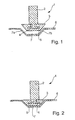
- the stop buffer 1 shown in Fig. 1 consists of a Buffer upper part 2 and a lower buffer part 3, which as a support the buffer 1 on a sheet 6 is used.
- the upper buffer part 2 over its upper end, not shown, at a first likewise component not shown attached.
- the first component can be, for example, a hood of a motor vehicle, which can be pivoted on a second component, namely the body of the motor vehicle is attached. But it is also possible that the upper buffer part 2 is attached to the fixed component becomes.
- the attachment of the upper part 2 to the first movable Component is made using known fasteners, such as clips, Screws, bolts, etc. Usually several buffers are used Support of the two components can be provided against each other.
- the lower end of the upper buffer part 2 has a cross section t-shaped section 4.
- the lower buffer part 3 has a conical shape and has a t-shaped cross section Cavity 5 on.
- the t-shaped section 4 of the upper buffer part 2 is arranged in the t-shaped cavity 5 of the lower buffer part 3.
- the cavity 5 is wider than the section 4, so that the lower buffer part 3 relative to the upper buffer part 2 in a radial Direction can move.
- Cavity 5 and section 4 are coordinated in their dimensions so that a movement in the axial direction and a step out of section 4 from the cavity 5 is not possible.
- a sheet 6 of the second Component the fixed body.
- This Sheet 6 has a recess 7, the side flanks 7a and 7b have an angle which corresponds to the conical side surfaces of the Correspond to lower buffer part 3.
- the recess 7 is used for receiving and guidance of the lower buffer part 3 of the buffer 1, if the components are in the closed position.
- the adjustment is carried out axially Direction using known methods. For example here the adjustment via a threaded rod and lock nuts called.
- the adjustment in the radial direction i.e. the alignment of the lower buffer part 3 on the recess 7 takes place according to the invention automatically during the first installation
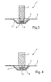
- the buffer lower part 3 is at the moment of the attack by the interaction of Buffer 1 and plate 6 aligned in the radial direction. This Situation is shown in Fig. 2.
- Opposite the illustration in Fig. 1 the lower buffer part 3 is relative to the upper buffer part 2 shifted to the right. In this position there can be a fixation of upper buffer part 2 with lower buffer part 3.
- upper buffer part 2 and lower buffer part 3 are eccentric Center piece 8 connected.
- the eccentric centerpiece 8 consists of in the illustrated embodiment two circular disks, one above the other and rotatable in the buffer parts are arranged.
- any other type of eccentric centerpiece which a movement of the lower buffer part 3 relative to the upper buffer part 2 allows in the radial direction.
- When closing the movable first component is the lower buffer part 3 by the recess 7 pressed into the correct position. It moves the eccentric center piece into the corresponding one Location.
- the radial alignment of the buffer 1 also takes place here through the interaction of buffer 1 and plate 6 at the moment of Attack.
- the fixation can thereby in the described embodiments take place from below through the lower buffer part 3 Safety bolt, not shown, or a screw in the Buffer top 2 is introduced and thereby a movement of Lower buffer part 3 is prevented relative to upper buffer part 2 becomes.
- the fixation can also take place in that an adhesive is introduced into the cavity 5 is in the closed position after Self-adjustment hardens. This possibility brings the special Advantage with it that in addition to the adjustment also the fixation done by itself while the two face each other moving components are in the closed position.
- the buffer 1 can also be fixed in the radial direction record and so the moving part in this direction support.
- the recess 5 can be filled with adhesive be that hardens when upper buffer part 2 and lower buffer part 3 at the moment of its stop in the radial direction optimally aligned positions to have.
- adhesive be that hardens when upper buffer part 2 and lower buffer part 3 at the moment of its stop in the radial direction optimally aligned positions to have.
- section 4 of the upper part 2 a T-shaped in cross section Have shape.
- the embodiment shown in FIGS. 5 and 6 follows another principle for self-adjustment of the buffer 1 in the radial Direction.
- the buffer 1 shown exists again from two parts, a buffer upper part 2 and a lower buffer part 3. However, these are so interconnected that a relative movement between the upper part 2 and lower part 3 not possible.
- the connection between the two buffer parts 2 and 3 is designed in the form of a predetermined breaking point that it can be separated easily. This predetermined breaking point can, for example, by film hinges, which are thin Plastic webs, between upper buffer part 2 and lower buffer part 3 can be realized.
- the buffer 1 is the same as that previously described Embodiments with the first, movable Component fixed by known means. There is also an attachment here the upper buffer part 2 on the second, fixed Component possible. Then the first movable component in brought a closed position. As a result, buffer 1 comes along the lower side of the lower buffer part 3 in contact with the Sheet 6. In this position, the lower buffer part 3 on the Sheet 6 fixed. This can be done with screws and nuts or after a preferred embodiment using one on the bottom of the lower buffer part 3 attached adhesive, which in The closed position of the two components as soon as the lower part of the buffer 3 comes into contact with the sheet 6, hardens, take place. If the lower buffer part 3 is firmly connected to the sheet 6, can the first moving component can be opened again.
- upper buffer part 2 and lower buffer part 3 are only separated, after being attached to the two components in the closed position have been, they are optimal to each other in the radial direction aligned.
- the separation point 9 is conical, so that the lower buffer part 3 with respect to the upper buffer part 2 acts as a guide.
- the buffer top 2 can be done after Assembling both axial and radial forces Take direction and thus optimally support the bonnet.
Landscapes
- Engineering & Computer Science (AREA)
- General Engineering & Computer Science (AREA)
- Mechanical Engineering (AREA)
- Health & Medical Sciences (AREA)
- Child & Adolescent Psychology (AREA)
- Chemical & Material Sciences (AREA)
- Combustion & Propulsion (AREA)
- Physics & Mathematics (AREA)
- Acoustics & Sound (AREA)
- Aviation & Aerospace Engineering (AREA)
- Vibration Dampers (AREA)
- Springs (AREA)
Abstract
Description
- Fig. 1:
- eine Seitenansicht eines erfindungsgemäßen Anschlagpuffers vor dem Moment des Anschlags;
- Fig. 2:
- eine Seitenansicht des erfindungsgemäßen Anschlagpuffers gemäß Fig. 1 nach dem Moment des Anschlags;
- Fig. 3:
- eine Seitenansicht einer weiteren Ausführungsform eines erfindungsgemäßen Anschlagpuffers nach dem Moment des Anschlags;
- Fig. 4:
- eine Seitenansicht einer weiteren Ausführungsform eines erfindungsgemäßen Anschlagpuffers nach dem Moment des Anschlags;
- Fig. 5:
- eine Seitenansicht einer weiteren Ausführungsform eines erfindungsgemäßen Anschlagpuffers vor dem Moment des Anschlags und
- Fig. 6:
- eine Seitenansicht eines Anschlagpuffers gemäß Fig. 5 nach dem Moment des Anschlags.
Claims (22)
- Verfahren zum Ausrichten eines Anschlagpuffers zum Abstützen eines ersten Bauteils an einem zweiten, wobei das erste Bauteil beweglich gegenüber dem zweiten ist, insbesondere zum Abstützen eines beweglichen Karosserieteils eines Kraftfahrzeugs an einem festen Karosserieteil,bei dem zunächst der Anschlagpuffer an einem der Bauteile befestigt wird,sodann die Bauteile in eine Schließstellung und damit der Puffer zur Anlage an das andere Bauteil gebracht wird,wobei durch das Zusammenwirken des Puffers mit den beiden Bauteilen im Moment des Anschlags beim Schließen eine Selbstjustierung des Puffers in radialer Richtung erfolgt.
- Verfahren nach Anspruch 1,
dadurch gekennzeichnet, daß die Selbstjustierung über relativ zueinander bewegliche Teile des Puffers und Führungen in den Bauteilen erfolgt, in die mindestens eines der beweglichen Pufferteile im Moment des Anschlags eingreift. - Verfahren nach Anspruch 1,
dadurch gekennzeichnet, daß die Selbstjustierung über ein vom Puffer getrenntes Teil und Führungen in den Bauteilen erfolgt, in die das vom Puffer getrennte Teil vor dem Moment des Anschlags eingelegt wird. - Verfahren nach einem der Ansprüche 1 bis 3,
dadurch gekennzeichnet, daß die Pufferteile in der Schließstellung in der mittels Selbstjustierung gefundenen Stellung zueinander fixiert werden. - Verfahren nach einem der Ansprüche 1 bis 3,
dadurch gekennzeichnet, daß das erste Bauteil nach dem Schließen in eine geöffnete Stellung gebracht wird und die beim Schließen mittels Selbstjustierung gefundene Stellung der Pufferteile zueinander fixiert werden. - Verfahren nach einem der Ansprüche 1 bis 5,
dadurch gekennzeichnet, daß die Fixierung durch einen Klebstoff erfolgt. - Verfahren nach einem der Ansprüche 1 bis 5
dadurch gekennzeichnet, daß die Fixierung mittels Schrauben und/oder Bolzen erfolgt. - Verfahren nach Anspruch 1 oder 2,
dadurch gekennzeichnet, daß die Selbstjustierung dadurch erfolgt, daß der an einem der Bauteile befestigte Puffer im Moment des Anschlags mit dem anderen Bauteil verbunden wird und dadurch der Puffer beim Öffnen in zwei Teile geteilt wird, wobei die Trennstelle zwischen den beiden Pufferteilen als Führung fungiert. - Puffer zum Abstützen eines ersten Bauteils an einem zweiten, wobei das erste Bauteil beweglich gegenüber dem zweiten ist, insbesondere zum Abstützen eines beweglichen Karosserieteils eines Kraftfahrzeugs an einem festen Karosserieteil, welcher ein Pufferoberteil und ein Pufferunterteil aufweist, wobei das Pufferoberteil an einem der Bauteile befestigt ist,
dadurch gekennzeichnet, daß der Puffer (1) einteilig und das Pufferunterteil (3) relativ zum Pufferoberteil (2) beweglich ist. - Puffer zum Abstützen eines ersten Bauteils an einem zweiten, wobei das erste Bauteil beweglich gegenüber dem zweiten ist, insbesondere zum Abstützen eines beweglichen Karosserieteils eines Kraftfahrzeugs an einem festen Karosserieteil, welcher ein Pufferoberteil und ein Pufferunterteil aufweist, wobei das Pufferoberteil an einem der Bauteile befestigt ist,
dadurch gekennzeichnet, daß der Puffer (1) zweiteilig ist, wobei das Pufferunterteil (3) einen Bereich (5) zur Aufnahme mindestens eines Abschnitts (4) des Pufferoberteils (2) aufweist. - Puffer nach Anspruch 9 oder 10,
dadurch gekennzeichnet, daß das Pufferunterteil (3) eine Form aufweist, die einem Gegenstück in dem Bauteil entspricht, das der Puffer (1) im Moment des Anschlags berührt. - Puffer nach einem der Ansprüche 9 bis 11,
dadurch gekennzeichnet, daß das Pufferunterteil (3) im Querschnitt einen t-förmigen Hohlraum (5) aufweist. - Puffer nach einem der Ansprüche 9 bis 12,
dadurch gekennzeichnet, daß das Pufferoberteil (2) im Querschnitt einen t-förmigen Abschnitt (4) aufweist, der in den Hohlraum (5) eingreift. - Puffer nach einem der Ansprüche 9, 11 bis 13,
dadurch gekennzeichnet, daß der Hohlraum (5) größer ist als der Abschnitt (4), so daß sich das Pufferunterteil (3) relativ zum Pufferoberteil (2) in radialer Richtung bewegen kann. - Puffer nach Anspruch 9 oder 10,
dadurch gekennzeichnet, daß Pufferoberteil (2) und Pufferunterteil (4) über ein exzentrisches Mittelstück (8) beweglich miteinander verbunden sind. - Puffer nach Anspruch 15,
dadurch gekennzeichnet, daß das exzentrische Mittelstück (8) aus zwei außermittig übereinander angeordnete Kreisscheiben besteht. - Puffer zum Abstützen eines ersten Bauteils an einem zweiten, wobei das erste Bauteil beweglich gegenüber dem zweiten ist, insbesondere zum Abstützen eines beweglichen Karosserieteils eines Kraftfahrzeugs an einem festen Karosserieteil, welcher ein Pufferoberteil und ein Pufferunterteil aufweist, wobei das Pufferoberteil an einem der beiden Bauteile befestigt ist,
dadurch gekennzeichnet, daß der Puffer (1) einteilig ist und Pufferunterteil (3) und Pufferoberteil (2) lösbar miteinander verbunden sind. - Puffer nach Anspruch 17,
dadurch gekennzeichnet, daß Pufferunterteil (3) und Pufferoberteil (2) über ein Filmscharnier miteinander verbunden sind. - Puffer nach Anspruch 17 oder 18,
dadurch gekennzeichnet, daß die Trennstelle zwischen Pufferoberteil (2) und Pufferunterteil (3) konisch verläuft. - Puffer nach einem der Ansprüche 17 bis 19,
dadurch gekennzeichnet, daß das Pufferunterteil (3) Mittel zum Befestigen an einem der Bauteile aufweist. - Puffer nach Anspruch 20,
dadurch gekennzeichnet, daß das Pufferunterteil (3) eine Klebstoffschicht zum Befestigen des Pufferunterteils (3) an einem der Bauteile aufweist. - Puffer nach Anspruch 20,
dadurch gekennzeichnet, daß das Pufferunterteil (3) einen Gewindebolzen zum Befestigen des Pufferunterteils (3) an einem der Bauteile aufweist.
Applications Claiming Priority (2)
| Application Number | Priority Date | Filing Date | Title |
|---|---|---|---|
| DE10048236 | 2000-09-29 | ||
| DE2000148236 DE10048236A1 (de) | 2000-09-29 | 2000-09-29 | Anschlagpuffer |
Publications (3)
| Publication Number | Publication Date |
|---|---|
| EP1193090A2 true EP1193090A2 (de) | 2002-04-03 |
| EP1193090A3 EP1193090A3 (de) | 2003-10-29 |
| EP1193090B1 EP1193090B1 (de) | 2007-06-13 |
Family
ID=7658054
Family Applications (1)
| Application Number | Title | Priority Date | Filing Date |
|---|---|---|---|
| EP20010121123 Expired - Lifetime EP1193090B1 (de) | 2000-09-29 | 2001-09-04 | Anschlagpuffer |
Country Status (2)
| Country | Link |
|---|---|
| EP (1) | EP1193090B1 (de) |
| DE (2) | DE10048236A1 (de) |
Cited By (2)
| Publication number | Priority date | Publication date | Assignee | Title |
|---|---|---|---|---|
| EP1503018A3 (de) * | 2003-07-30 | 2010-05-05 | Bayerische Motorenwerke AG | Fahrzeug mit zumindest einer Fahrzeugklappe |
| DE102011114267B3 (de) * | 2011-09-26 | 2012-12-27 | Elastomer Solutions GmbH | Verfahren zum Ausrichten eines Anschlagpuffers für eine Tür oder Haube eines Kraftfahrzeugs und Anschlagpuffer |
Families Citing this family (3)
| Publication number | Priority date | Publication date | Assignee | Title |
|---|---|---|---|---|
| DE102005039332A1 (de) * | 2005-08-19 | 2007-02-22 | Bayerische Motoren Werke Ag | Verfahren zur exakten Positionierung eines Anschlagpuffers sowie Anschlagpuffer |
| KR101223891B1 (ko) * | 2010-12-30 | 2013-01-17 | 한국항공우주연구원 | 인공위성 반작용휠 수동 진동저감장치 |
| DE102018211785A1 (de) | 2018-07-16 | 2020-01-16 | Bayerische Motoren Werke Aktiengesellschaft | Einstellelement zum Ausgleichen von Toleranzen sowie Befestigungsanordnung mit einem solchen Einstellelement |
Citations (1)
| Publication number | Priority date | Publication date | Assignee | Title |
|---|---|---|---|---|
| DE19520492A1 (de) | 1995-06-03 | 1996-12-05 | Opel Adam Ag | Anschlagpuffer und Verfahren zum Verspannen von zwei Bauteilen mit einem solchen Anschlagpuffer |
Family Cites Families (4)
| Publication number | Priority date | Publication date | Assignee | Title |
|---|---|---|---|---|
| US5482348A (en) * | 1993-07-12 | 1996-01-09 | Ford Motor Company | Vehicle hood support post member |
| DE19514944C1 (de) * | 1995-04-22 | 1996-10-24 | Itw Ateco Gmbh | Selbstjustierender Dämfungsanschlag für bewegliche Teile |
| EP0892140B1 (de) * | 1997-07-17 | 2008-02-06 | Volkswagen Aktiengesellschaft | Verfahren zum Herstellen einer Anschlagpufferanordnung, insbesondere für Fahrzeug-Karosserieteile |
| DE19811165B4 (de) * | 1998-03-14 | 2010-11-11 | Volkswagen Ag | Positionierelement zur Ausrichtung von Karosserieteilen |
-
2000
- 2000-09-29 DE DE2000148236 patent/DE10048236A1/de not_active Withdrawn
-
2001
- 2001-09-04 DE DE50112620T patent/DE50112620D1/de not_active Expired - Lifetime
- 2001-09-04 EP EP20010121123 patent/EP1193090B1/de not_active Expired - Lifetime
Patent Citations (1)
| Publication number | Priority date | Publication date | Assignee | Title |
|---|---|---|---|---|
| DE19520492A1 (de) | 1995-06-03 | 1996-12-05 | Opel Adam Ag | Anschlagpuffer und Verfahren zum Verspannen von zwei Bauteilen mit einem solchen Anschlagpuffer |
Cited By (2)
| Publication number | Priority date | Publication date | Assignee | Title |
|---|---|---|---|---|
| EP1503018A3 (de) * | 2003-07-30 | 2010-05-05 | Bayerische Motorenwerke AG | Fahrzeug mit zumindest einer Fahrzeugklappe |
| DE102011114267B3 (de) * | 2011-09-26 | 2012-12-27 | Elastomer Solutions GmbH | Verfahren zum Ausrichten eines Anschlagpuffers für eine Tür oder Haube eines Kraftfahrzeugs und Anschlagpuffer |
Also Published As
| Publication number | Publication date |
|---|---|
| EP1193090B1 (de) | 2007-06-13 |
| DE50112620D1 (de) | 2007-07-26 |
| DE10048236A1 (de) | 2002-04-11 |
| EP1193090A3 (de) | 2003-10-29 |
Similar Documents
| Publication | Publication Date | Title |
|---|---|---|
| EP0694465B1 (de) | Kraftfahrzeugkarosserie mit integriertem Strukturquerträger | |
| DE4011186C2 (de) | ||
| EP2683591B1 (de) | Lenkrad für ein kraftfahrzeug | |
| DE102020108110B3 (de) | Türband und Verfahren zu dessen Montage | |
| DE69619641T2 (de) | Lineare Antriebsvorrichtung | |
| EP2180121B1 (de) | Vorrichtung zur Festlegung der Lage einer Klappe | |
| EP3275733B1 (de) | Scheinwerferbefestigungssystem für kraftfahrzeuge und verfahren | |
| WO2021048166A1 (de) | Türbaugruppe für eine fahrzeugtür mit einer an einem türmodul in einer montageposition gehaltenen türverstellbaugruppe und montageverfahren | |
| EP1193090B1 (de) | Anschlagpuffer | |
| EP2336468B1 (de) | Beschlaggarnitur für zwei Schiebetürflügel | |
| EP1317594A1 (de) | Türbetätigungsaggregat für insbesondere kraftfahrzeuge | |
| DE102012010429A1 (de) | Befestigungsverfahren und Befestigungseinrichtung | |
| EP0940531A1 (de) | Schliesshilfe für Türen oder Klappen eines Kraftfahrzeuges | |
| DE102018111959A1 (de) | Schwimmende, verliergesicherte Anordnung eines Verbindungselementes an einem Bauteil | |
| EP3786405B1 (de) | Möbelantrieb zum bewegen eines bewegbar gelagerten möbelteiles | |
| DE102015010561A1 (de) | Verfahren zum Ausrichten eines ersten Bauteils relativ zu einem zweiten Bauteil eines Kraftwagens | |
| EP3045643A1 (de) | Torblatt | |
| EP1243214B1 (de) | Scharnier und Raumtrennvorrichtung, insbesondere Duschkabine mit Scharnier zum schwenkbaren Lagern insbesondere einer Glastür | |
| EP1637426A2 (de) | Puffersystem | |
| DE102006046266B4 (de) | Spannvorrichtung für eine Fronthaube | |
| DE10013604B4 (de) | Fixierelement | |
| DE10016144A1 (de) | Vorrichtung zum Justieren einer Baugruppe, insbesondere einer Instrumententafel eines Kraftfahrzeuges | |
| DE4218253A1 (de) | Scharnier zur schwenkbaren anlenkung einer klappe nach art einer frontklappe eines kraftfahrzeugs und verfahren zur justierung des scharniers | |
| DE102019109408B4 (de) | Zentriervorrichtung, die eine zumindest einachsige Zentrierung einer Schlossvorrichtung einer Heckklappe eines Fahrzeugs gewährleistet, Schlossvorrichtung mit einer solchen Zentriervorrichtung und Verfahren zur Zentrierung einer Heckklappe | |
| DE102004034425B4 (de) | Fensterheberanordnung zum Betätigen der Scheibe eines Fahrzeuges, insbesondere eines Cabrios |
Legal Events
| Date | Code | Title | Description |
|---|---|---|---|
| PUAI | Public reference made under article 153(3) epc to a published international application that has entered the european phase |
Free format text: ORIGINAL CODE: 0009012 |
|
| AK | Designated contracting states |
Kind code of ref document: A2 Designated state(s): AT BE CH CY DE DK ES FI FR GB GR IE IT LI LU MC NL PT SE TR |
|
| AX | Request for extension of the european patent |
Free format text: AL;LT;LV;MK;RO;SI |
|
| PUAL | Search report despatched |
Free format text: ORIGINAL CODE: 0009013 |
|
| AK | Designated contracting states |
Kind code of ref document: A3 Designated state(s): AT BE CH CY DE DK ES FI FR GB GR IE IT LI LU MC NL PT SE TR |
|
| AX | Request for extension of the european patent |
Extension state: AL LT LV MK RO SI |
|
| RIC1 | Information provided on ipc code assigned before grant |
Ipc: 7F 16F 1/44 B Ipc: 7B 60J 5/10 A Ipc: 7F 16F 1/373 B Ipc: 7F 16F 15/08 B Ipc: 7E 05F 5/02 B |
|
| 17P | Request for examination filed |
Effective date: 20030923 |
|
| 17Q | First examination report despatched |
Effective date: 20040524 |
|
| AKX | Designation fees paid |
Designated state(s): DE FR GB SE |
|
| GRAP | Despatch of communication of intention to grant a patent |
Free format text: ORIGINAL CODE: EPIDOSNIGR1 |
|
| RAP1 | Party data changed (applicant data changed or rights of an application transferred) |
Owner name: DAIMLERCHRYSLER AG |
|
| GRAS | Grant fee paid |
Free format text: ORIGINAL CODE: EPIDOSNIGR3 |
|
| GRAA | (expected) grant |
Free format text: ORIGINAL CODE: 0009210 |
|
| AK | Designated contracting states |
Kind code of ref document: B1 Designated state(s): DE FR GB SE |
|
| REG | Reference to a national code |
Ref country code: GB Ref legal event code: FG4D Free format text: NOT ENGLISH |
|
| REG | Reference to a national code |
Ref country code: SE Ref legal event code: TRGR |
|
| REF | Corresponds to: |
Ref document number: 50112620 Country of ref document: DE Date of ref document: 20070726 Kind code of ref document: P |
|
| GBT | Gb: translation of ep patent filed (gb section 77(6)(a)/1977) |
Effective date: 20070719 |
|
| ET | Fr: translation filed | ||
| RAP2 | Party data changed (patent owner data changed or rights of a patent transferred) |
Owner name: DAIMLER AG |
|
| PLBE | No opposition filed within time limit |
Free format text: ORIGINAL CODE: 0009261 |
|
| STAA | Information on the status of an ep patent application or granted ep patent |
Free format text: STATUS: NO OPPOSITION FILED WITHIN TIME LIMIT |
|
| 26N | No opposition filed |
Effective date: 20080314 |
|
| PGFP | Annual fee paid to national office [announced via postgrant information from national office to epo] |
Ref country code: FR Payment date: 20080912 Year of fee payment: 8 |
|
| PGFP | Annual fee paid to national office [announced via postgrant information from national office to epo] |
Ref country code: GB Payment date: 20080918 Year of fee payment: 8 |
|
| PGFP | Annual fee paid to national office [announced via postgrant information from national office to epo] |
Ref country code: SE Payment date: 20080912 Year of fee payment: 8 |
|
| REG | Reference to a national code |
Ref country code: FR Ref legal event code: CD |
|
| EUG | Se: european patent has lapsed | ||
| GBPC | Gb: european patent ceased through non-payment of renewal fee |
Effective date: 20090904 |
|
| REG | Reference to a national code |
Ref country code: FR Ref legal event code: ST Effective date: 20100531 |
|
| PGFP | Annual fee paid to national office [announced via postgrant information from national office to epo] |
Ref country code: DE Payment date: 20100211 Year of fee payment: 9 |
|
| PG25 | Lapsed in a contracting state [announced via postgrant information from national office to epo] |
Ref country code: FR Free format text: LAPSE BECAUSE OF NON-PAYMENT OF DUE FEES Effective date: 20090930 |
|
| PG25 | Lapsed in a contracting state [announced via postgrant information from national office to epo] |
Ref country code: GB Free format text: LAPSE BECAUSE OF NON-PAYMENT OF DUE FEES Effective date: 20090904 |
|
| PG25 | Lapsed in a contracting state [announced via postgrant information from national office to epo] |
Ref country code: SE Free format text: LAPSE BECAUSE OF NON-PAYMENT OF DUE FEES Effective date: 20090905 |
|
| REG | Reference to a national code |
Ref country code: DE Ref legal event code: R119 Ref document number: 50112620 Country of ref document: DE Effective date: 20110401 |
|
| PG25 | Lapsed in a contracting state [announced via postgrant information from national office to epo] |
Ref country code: DE Free format text: LAPSE BECAUSE OF NON-PAYMENT OF DUE FEES Effective date: 20110401 |