EP1192363B1 - Magnetische lagerung - Google Patents
Magnetische lagerung Download PDFInfo
- Publication number
- EP1192363B1 EP1192363B1 EP01962549A EP01962549A EP1192363B1 EP 1192363 B1 EP1192363 B1 EP 1192363B1 EP 01962549 A EP01962549 A EP 01962549A EP 01962549 A EP01962549 A EP 01962549A EP 1192363 B1 EP1192363 B1 EP 1192363B1
- Authority
- EP
- European Patent Office
- Prior art keywords
- bearing
- radial
- axial
- magnetic bearing
- rotor
- Prior art date
- Legal status (The legal status is an assumption and is not a legal conclusion. Google has not performed a legal analysis and makes no representation as to the accuracy of the status listed.)
- Expired - Lifetime
Links
- 239000002887 superconductor Substances 0.000 claims abstract description 10
- 230000007704 transition Effects 0.000 claims abstract description 8
- 238000006073 displacement reaction Methods 0.000 claims description 5
- 230000005284 excitation Effects 0.000 description 18
- 238000001816 cooling Methods 0.000 description 8
- 238000007710 freezing Methods 0.000 description 8
- 230000008014 freezing Effects 0.000 description 8
- 238000000034 method Methods 0.000 description 6
- 230000001419 dependent effect Effects 0.000 description 2
- 230000000750 progressive effect Effects 0.000 description 2
- 230000005540 biological transmission Effects 0.000 description 1
- 238000010586 diagram Methods 0.000 description 1
- 238000009413 insulation Methods 0.000 description 1
- 230000036316 preload Effects 0.000 description 1
Images


Classifications
-
- F—MECHANICAL ENGINEERING; LIGHTING; HEATING; WEAPONS; BLASTING
- F16—ENGINEERING ELEMENTS AND UNITS; GENERAL MEASURES FOR PRODUCING AND MAINTAINING EFFECTIVE FUNCTIONING OF MACHINES OR INSTALLATIONS; THERMAL INSULATION IN GENERAL
- F16C—SHAFTS; FLEXIBLE SHAFTS; ELEMENTS OR CRANKSHAFT MECHANISMS; ROTARY BODIES OTHER THAN GEARING ELEMENTS; BEARINGS
- F16C32/00—Bearings not otherwise provided for
- F16C32/04—Bearings not otherwise provided for using magnetic or electric supporting means
- F16C32/0406—Magnetic bearings
- F16C32/0408—Passive magnetic bearings
- F16C32/0436—Passive magnetic bearings with a conductor on one part movable with respect to a magnetic field, e.g. a body of copper on one part and a permanent magnet on the other part
- F16C32/0438—Passive magnetic bearings with a conductor on one part movable with respect to a magnetic field, e.g. a body of copper on one part and a permanent magnet on the other part with a superconducting body, e.g. a body made of high temperature superconducting material such as YBaCuO
-
- F—MECHANICAL ENGINEERING; LIGHTING; HEATING; WEAPONS; BLASTING
- F16—ENGINEERING ELEMENTS AND UNITS; GENERAL MEASURES FOR PRODUCING AND MAINTAINING EFFECTIVE FUNCTIONING OF MACHINES OR INSTALLATIONS; THERMAL INSULATION IN GENERAL
- F16C—SHAFTS; FLEXIBLE SHAFTS; ELEMENTS OR CRANKSHAFT MECHANISMS; ROTARY BODIES OTHER THAN GEARING ELEMENTS; BEARINGS
- F16C37/00—Cooling of bearings
- F16C37/005—Cooling of bearings of magnetic bearings
-
- Y—GENERAL TAGGING OF NEW TECHNOLOGICAL DEVELOPMENTS; GENERAL TAGGING OF CROSS-SECTIONAL TECHNOLOGIES SPANNING OVER SEVERAL SECTIONS OF THE IPC; TECHNICAL SUBJECTS COVERED BY FORMER USPC CROSS-REFERENCE ART COLLECTIONS [XRACs] AND DIGESTS
- Y10—TECHNICAL SUBJECTS COVERED BY FORMER USPC
- Y10S—TECHNICAL SUBJECTS COVERED BY FORMER USPC CROSS-REFERENCE ART COLLECTIONS [XRACs] AND DIGESTS
- Y10S505/00—Superconductor technology: apparatus, material, process
- Y10S505/825—Apparatus per se, device per se, or process of making or operating same
- Y10S505/902—Railway, e.g. rapid transit
- Y10S505/903—Suspension, e.g. magnetic, electrodynamic
Definitions
- the invention relates to a magnetic bearing of a rotor in one Stator, with at least one magnetic bearing, the one stator part and one for this purpose in the operating position coaxial and contactlessly arranged rotor part has whose effective bearing surface by a permanent magnet having radial excitation system is formed, while the stator part the radial excitation system while observing an annular Air gap concentrically enclosing high-temperature superconductor having.
- the component to be stored for example the rotor of a machine after freezing from a Freezing position by forces, e.g. Dead weight or operating loads in which Operating position must be moved.
- forces e.g. Dead weight or operating loads in which Operating position must be moved.
- the non-linear Spring characteristic of the bearing which is often progressive with OFC, OFCo, ZFC, with MFC, however, is degressive, is a minimum route for this shift required to get to a working point with sufficient rigidity reach.
- the required Stiffness of the bearing in the working point due to a correspondingly large Surface needs to be adjusted, but this is unnecessarily expensive and expensive impractical dimensions of the bearing results.
- the invention is therefore based on the object, the specific rigidity of superconducting bearings while avoiding the above disadvantages improve.
- the High-temperature superconductor in at least two circular segment-shaped HTSL partial shells which is divided from a position in a warm storage condition, in of each HTSL subshell from the radial excitation system a first has radial distance after the transition to the superconducting State with an actuator in the radial direction in a working position a second, smaller radial distance (operating gap) from the radial Excitation system are mutually displaceable.
- a magnetic bearing according to the invention can also be characterized be by an additional thrust bearing, in which two each other opposite each other, arranged at an axial distance from each other axial excitation systems equipped with permanent magnets each have an axial form directed washer-shaped bearing effective surface of the rotor part, which as a stator part, a plane arranged coaxially to the rotor part ring-shaped HTSL axial bearing washer, which consists of a Position when the bearing is warm, in which each HTSL thrust bearing washer from the assigned axial excitation system a first axial distance has, after the transition to the superconducting state via a Actuator in the axial direction in a working position with a second, smaller axial distance from the axial excitation system away from each other are movable.
- Figure 1 shows a radial magnetic bearing 1, the stator part 2 and one for this purpose arranged coaxially in the operating position as a shaft rotor part 3 shown, the effective bearing surface by a Permanent magnets 4 with interposed pole pieces 5 having radial excitation system 6 is formed.
- the stator part 2 has a high-temperature superconductor (HTSL) concentrically surrounding the radial excitation system 6 while observing an annular air gap 10, which according to the invention is divided into two circular segment-shaped HTSL half-shells 7, 8 which have thermal insulation on their segment surface facing the radial excitation system 6 9 are covered and, in their working position shown in FIG. 1, have a radial distance ⁇ o from the radial excitation system 6 forming the bearing active surface.
- HTSL high-temperature superconductor
- FIG. 2 shows that the two HTSL half shells 7, 8 assume the positions shown in dashed lines in the warm storage state, in which the upper HTSL half shell 7 'has a radial distance ⁇ k1 and the lower HTSL half shell 8' from the middle parting line has a radial distance from k2 , in the exemplary embodiment shown ⁇ k2 > ⁇ k1 .
- the HTSL half-shells 7, 8 are moved apart into the position shown in dashed lines with the aid of an actuator 12, which can have a motor spindle 13, so that a radial air gap thickness ⁇ k > ⁇ o results.
- the HTSL half-shells 7, 8 are moved together with the help of the actuators 12 into the working position shown with solid lines until the operating gap ⁇ o shown in FIG. 1 is established.
- the radial gaps ⁇ k for the upper and lower bearing shells 7 ', 8' are selected differently in order to achieve weight compensation of the rotor weight through this asymmetry, the rotor part 3 remaining almost exactly in the geometric center of the radial magnetic bearing 1.
- a working point of the bearing can now be set which has a significantly higher rigidity at the working point.
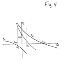
- FIG. 4 where the basic characteristics of the OFCo method for the upper and lower HTSL half-shell 7, 8 are shown.
- the point m ⁇ g on the F ⁇ force axis indicates the weight of the entire rotor.
- each HTSL half shell / radial Excitation system combination By superimposing the stiffness characteristics, each HTSL half shell / radial Excitation system combination an increased rigidity of the Achieve total storage at the working point.
- Figure 3 shows an axial bearing 14, in addition to the above described radial magnetic bearing 1 can be provided.
- the axial bearing 14 has two opposing, axially spaced axial excitation systems 16 each equipped with permanent magnets 15, each of which forms an axially directed annular disk-shaped bearing active surface of the rotor part 3.
- These two axial excitation systems 16 are each assigned as a stator part 17, a plane annular disk-shaped HTSL axial bearing disk 18, 19 arranged coaxially to the rotor part 3, which from a position shown in broken lines in a warm storage condition, in which each HTSL axial bearing disk 18 ', 19' is assigned by the one axial excitation system 16 has a first axial distance ⁇ k , after the transition to the superconducting state via an actuator 12 in the axial direction in a working position shown in solid lines with a second, smaller axial distance ⁇ o from the axial excitation system 16 can be moved away from each other ,
- the achieved according to the invention radially or optionally axially and radially preloaded bearing has an anisotropy of rigidity that on the number of HTSL partial shells used for the radial magnetic bearing 1 is dependent.
Landscapes
- Engineering & Computer Science (AREA)
- General Engineering & Computer Science (AREA)
- Mechanical Engineering (AREA)
- Magnetic Bearings And Hydrostatic Bearings (AREA)
- Connection Of Motors, Electrical Generators, Mechanical Devices, And The Like (AREA)
Applications Claiming Priority (3)
| Application Number | Priority Date | Filing Date | Title |
|---|---|---|---|
| DE10034922 | 2000-07-18 | ||
| DE10034922A DE10034922C2 (de) | 2000-07-18 | 2000-07-18 | Magnetische Lagerung |
| PCT/DE2001/002602 WO2002006688A1 (de) | 2000-07-18 | 2001-07-17 | Magnetische lagerung |
Publications (2)
| Publication Number | Publication Date |
|---|---|
| EP1192363A1 EP1192363A1 (de) | 2002-04-03 |
| EP1192363B1 true EP1192363B1 (de) | 2004-10-06 |
Family
ID=7649336
Family Applications (1)
| Application Number | Title | Priority Date | Filing Date |
|---|---|---|---|
| EP01962549A Expired - Lifetime EP1192363B1 (de) | 2000-07-18 | 2001-07-17 | Magnetische lagerung |
Country Status (5)
| Country | Link |
|---|---|
| US (1) | US6541885B2 (enExample) |
| EP (1) | EP1192363B1 (enExample) |
| JP (1) | JP3754671B2 (enExample) |
| DE (2) | DE10034922C2 (enExample) |
| WO (1) | WO2002006688A1 (enExample) |
Families Citing this family (19)
| Publication number | Priority date | Publication date | Assignee | Title |
|---|---|---|---|---|
| US7466051B2 (en) * | 2002-08-02 | 2008-12-16 | Kazuyuki Demachi | Superconducting magnetic bearing |
| US20040256935A1 (en) * | 2003-06-19 | 2004-12-23 | Andrew Kenny | Magnetic bearing with permanent magnet poles |
| DE10333733A1 (de) * | 2003-07-23 | 2005-02-24 | Forschungszentrum Jülich GmbH | Magnetisches Lagerelement |
| DE102005032673A1 (de) * | 2005-07-13 | 2007-01-18 | Renk Aktiengesellschaft | Geteiltes aktives Magnetlager |
| DE602006010022D1 (de) | 2006-03-16 | 2009-12-10 | Nexans | Hochtemperatursupraleitendes Magnetlager |
| US20090113999A1 (en) * | 2007-03-08 | 2009-05-07 | General Electric Company | Method for Testing a Rotor and Stator Assembly |
| DE102007028018A1 (de) | 2007-06-19 | 2008-12-24 | Nexans Superconductors Gmbh | Dämpfersystem für Hochtemperatur-Supraleiterlager |
| DE102007036603B4 (de) | 2007-08-02 | 2009-12-24 | Nexans | Hochtemperatur-Supraleiterlager mit verbesserter Lagernachführung |
| DE102007036605B4 (de) | 2007-08-02 | 2009-12-24 | Nexans | Stabilisiertes Hochtemperatur-Supraleiterlager |
| RU2383791C1 (ru) * | 2008-12-09 | 2010-03-10 | Федеральное государственное унитарное предприятие "Московское машиностроительное производственное предприятие "Салют" | Сверхпроводящий магнитный подшипник и способ его изготовления |
| RU2385424C1 (ru) * | 2008-12-26 | 2010-03-27 | Учреждение Российской Академии Наук Институт Машиноведения Им. А.А. Благонравова Ран | Подшипник скольжения с магнитопорошковой системой смазки |
| RU2413882C1 (ru) * | 2009-12-23 | 2011-03-10 | Федеральное государственное унитарное предприятие "Московское машиностроительное производственное предприятие "САЛЮТ" (ФГУП "ММПП "САЛЮТ") | Магнитный подшипник на высокотемпературных сверхпроводниках (варианты) |
| US10012263B2 (en) | 2012-09-28 | 2018-07-03 | Abb Research, Ltd | Rotors for rotating machines with hollow fiber-reinforced composite shaft |
| WO2014055221A2 (en) | 2012-10-01 | 2014-04-10 | Abb Research Ltd. | Electrical machine rotors |
| DE102013015487A1 (de) | 2013-09-19 | 2015-03-19 | Volker Dietz | Energieanlage bzw. Kraftwerk mit berührungsarm, berührungslos und/oder magnetisch gelagerten Welle |
| DE102013015489A1 (de) | 2013-09-19 | 2015-03-19 | Imo Holding Gmbh | Energieanlage bzw. Kraftwerk mit berührungsarm, berührungslos und/oder magnetisch gelagerten Welle |
| CN104763746B (zh) * | 2015-04-09 | 2017-05-10 | 东晶电子金华有限公司 | 一种低温超导飞轮用变间隙支承结构 |
| RU2605227C1 (ru) * | 2015-06-22 | 2016-12-20 | Федеральное государственное бюджетное образовательное учреждение высшего профессионального образования "Омский государственный технический университет" | Подшипниковый узел |
| CN114673728B (zh) * | 2020-12-24 | 2024-01-26 | 迈格钠磁动力股份有限公司 | 一种永磁推力悬浮轴承及其控制方法 |
Family Cites Families (5)
| Publication number | Priority date | Publication date | Assignee | Title |
|---|---|---|---|---|
| JP2547287B2 (ja) * | 1991-07-30 | 1996-10-23 | 株式会社四国総合研究所 | 超電導軸受装置 |
| JP3961032B2 (ja) * | 1993-12-13 | 2007-08-15 | シーメンス アクチエンゲゼルシヤフト | 回転子軸の磁気軸受装置 |
| GB9403580D0 (en) * | 1994-02-24 | 1994-04-13 | Coombs Timotha A | Bearing stiffener |
| DE19727550C2 (de) * | 1996-08-21 | 2002-05-08 | Canders Wolf R | Magnetische Lagerung eines Rotors in einem Stator |
| JP3348038B2 (ja) * | 1998-04-08 | 2002-11-20 | 韓国電力公社 | 強い浮上力の高温超伝導ベアリング、および、フライホイールエネルギー貯蔵装置 |
-
2000
- 2000-07-18 DE DE10034922A patent/DE10034922C2/de not_active Expired - Fee Related
-
2001
- 2001-07-17 EP EP01962549A patent/EP1192363B1/de not_active Expired - Lifetime
- 2001-07-17 WO PCT/DE2001/002602 patent/WO2002006688A1/de not_active Ceased
- 2001-07-17 US US10/088,375 patent/US6541885B2/en not_active Expired - Lifetime
- 2001-07-17 JP JP2002512558A patent/JP3754671B2/ja not_active Expired - Fee Related
- 2001-07-17 DE DE50103961T patent/DE50103961D1/de not_active Expired - Lifetime
Also Published As
| Publication number | Publication date |
|---|---|
| WO2002006688A1 (de) | 2002-01-24 |
| US6541885B2 (en) | 2003-04-01 |
| EP1192363A1 (de) | 2002-04-03 |
| JP3754671B2 (ja) | 2006-03-15 |
| DE10034922C2 (de) | 2003-01-16 |
| US20020135249A1 (en) | 2002-09-26 |
| DE10034922A1 (de) | 2002-02-07 |
| JP2004504553A (ja) | 2004-02-12 |
| DE50103961D1 (de) | 2004-11-11 |
Similar Documents
| Publication | Publication Date | Title |
|---|---|---|
| EP1192363B1 (de) | Magnetische lagerung | |
| DE2339772B2 (de) | Anordnung zur Befestigung einer supraleitenden Erregerwicklung im Läufer eines Turbogenerators | |
| DE102020104857A1 (de) | Antriebsanordnung für eine elektrische Antriebsachse | |
| EP3337996B1 (de) | Kupplungseinrichtung für hybridantrieb | |
| CH352892A (de) | Ziehkeil-Schaltgetriebe | |
| DE69316613T2 (de) | Magnetische Lagervorrichtung für das Kippen eines Drehkörpers in Bezug auf einen Ständerkörper | |
| DE102020122249B4 (de) | Elektrische Maschinenanordnung | |
| WO2022089684A1 (de) | Elektrische maschine, verfahren zur herstellung einer elektrischen maschine sowie elektrisch betreibbarer antriebsstrang | |
| DE19962191A1 (de) | Kugellager und Elektromagnetische Kupplung mit demselben | |
| DE3028106A1 (de) | Lageranordnung fuer werkzeugmaschienenspindeln | |
| DE102021120925A1 (de) | Antriebssystem für ein hybrides oder elektrisches Fahrzeug | |
| EP2318727B1 (de) | Magnetlager und verfahren zu dessen betrieb | |
| DE19715356A1 (de) | Vorrichtung zur Lagerung von schnelldrehenden Rotoren | |
| DE1600015B1 (de) | Elektromagnetisch betaetigbare Reibscheibenwechselkupplung | |
| DE102020206349A1 (de) | Bremseinrichtung für eine elektrische Antriebsachse, elektrische Antriebsachse für ein Fahrzeug und Verfahren zum Betreiben einer Bremseinrichtung für eine elektrische Antriebsachse | |
| DE102022104512B4 (de) | Elektrisch betreibbarer Achsantriebsstrang | |
| DE102023102102A1 (de) | Rotor und elektrische Maschine | |
| AT523777A2 (de) | Schwungradsysteme und zugehörige Verfahren | |
| WO2001031218A1 (de) | Doppelkupplung mit einem elektromagneten | |
| DE68917811T2 (de) | Stahl für Lager. | |
| DE102014210696A1 (de) | Elektrischer Zentralausrücker (EZA) mit Selbsthaltefeder | |
| DE102017004637B4 (de) | Ändern einer Übersetzung in einem Getriebe eines Fahrzeugs | |
| DE102010054455A1 (de) | Wälzlager sowie Lageranordnung umfassend ein Wälzlager und Verfahren zum Betreiben der Lageranordnung | |
| DE102008058319B4 (de) | Wälzlager | |
| WO2009033906A1 (de) | Wälzlagerung für axial gegeneinander verschiebbare bauteile, insbesondere für getriebe-schaltelemente |
Legal Events
| Date | Code | Title | Description |
|---|---|---|---|
| PUAI | Public reference made under article 153(3) epc to a published international application that has entered the european phase |
Free format text: ORIGINAL CODE: 0009012 |
|
| 17P | Request for examination filed |
Effective date: 20020116 |
|
| AK | Designated contracting states |
Kind code of ref document: A1 Designated state(s): AT BE CH CY DE DK ES FI FR GB GR IE IT LI LU MC NL PT SE TR |
|
| GRAP | Despatch of communication of intention to grant a patent |
Free format text: ORIGINAL CODE: EPIDOSNIGR1 |
|
| GRAS | Grant fee paid |
Free format text: ORIGINAL CODE: EPIDOSNIGR3 |
|
| GRAA | (expected) grant |
Free format text: ORIGINAL CODE: 0009210 |
|
| AK | Designated contracting states |
Kind code of ref document: B1 Designated state(s): DE FR IT |
|
| REG | Reference to a national code |
Ref country code: IE Ref legal event code: FG4D Free format text: GERMAN |
|
| REF | Corresponds to: |
Ref document number: 50103961 Country of ref document: DE Date of ref document: 20041111 Kind code of ref document: P |
|
| REG | Reference to a national code |
Ref country code: IE Ref legal event code: FD4D |
|
| ET | Fr: translation filed | ||
| PLBE | No opposition filed within time limit |
Free format text: ORIGINAL CODE: 0009261 |
|
| STAA | Information on the status of an ep patent application or granted ep patent |
Free format text: STATUS: NO OPPOSITION FILED WITHIN TIME LIMIT |
|
| 26N | No opposition filed |
Effective date: 20050707 |
|
| REG | Reference to a national code |
Ref country code: FR Ref legal event code: PLFP Year of fee payment: 16 |
|
| REG | Reference to a national code |
Ref country code: FR Ref legal event code: PLFP Year of fee payment: 17 |
|
| REG | Reference to a national code |
Ref country code: FR Ref legal event code: PLFP Year of fee payment: 18 |
|
| PGFP | Annual fee paid to national office [announced via postgrant information from national office to epo] |
Ref country code: IT Payment date: 20180724 Year of fee payment: 18 Ref country code: FR Payment date: 20180725 Year of fee payment: 18 Ref country code: DE Payment date: 20180614 Year of fee payment: 18 |
|
| REG | Reference to a national code |
Ref country code: DE Ref legal event code: R119 Ref document number: 50103961 Country of ref document: DE |
|
| PG25 | Lapsed in a contracting state [announced via postgrant information from national office to epo] |
Ref country code: DE Free format text: LAPSE BECAUSE OF NON-PAYMENT OF DUE FEES Effective date: 20200201 |
|
| PG25 | Lapsed in a contracting state [announced via postgrant information from national office to epo] |
Ref country code: FR Free format text: LAPSE BECAUSE OF NON-PAYMENT OF DUE FEES Effective date: 20190731 |
|
| PG25 | Lapsed in a contracting state [announced via postgrant information from national office to epo] |
Ref country code: IT Free format text: LAPSE BECAUSE OF NON-PAYMENT OF DUE FEES Effective date: 20190717 |