EP1191231A2 - Turbomachines - Google Patents
Turbomachines Download PDFInfo
- Publication number
- EP1191231A2 EP1191231A2 EP01106933A EP01106933A EP1191231A2 EP 1191231 A2 EP1191231 A2 EP 1191231A2 EP 01106933 A EP01106933 A EP 01106933A EP 01106933 A EP01106933 A EP 01106933A EP 1191231 A2 EP1191231 A2 EP 1191231A2
- Authority
- EP
- European Patent Office
- Prior art keywords
- casing
- grooves
- blades
- area
- impeller
- Prior art date
- Legal status (The legal status is an assumption and is not a legal conclusion. Google has not performed a legal analysis and makes no representation as to the accuracy of the status listed.)
- Granted
Links
Images


Classifications
-
- F—MECHANICAL ENGINEERING; LIGHTING; HEATING; WEAPONS; BLASTING
- F04—POSITIVE - DISPLACEMENT MACHINES FOR LIQUIDS; PUMPS FOR LIQUIDS OR ELASTIC FLUIDS
- F04D—NON-POSITIVE-DISPLACEMENT PUMPS
- F04D29/00—Details, component parts, or accessories
- F04D29/40—Casings; Connections of working fluid
- F04D29/42—Casings; Connections of working fluid for radial or helico-centrifugal pumps
- F04D29/426—Casings; Connections of working fluid for radial or helico-centrifugal pumps especially adapted for liquid pumps
- F04D29/4273—Casings; Connections of working fluid for radial or helico-centrifugal pumps especially adapted for liquid pumps suction eyes
-
- F—MECHANICAL ENGINEERING; LIGHTING; HEATING; WEAPONS; BLASTING
- F04—POSITIVE - DISPLACEMENT MACHINES FOR LIQUIDS; PUMPS FOR LIQUIDS OR ELASTIC FLUIDS
- F04D—NON-POSITIVE-DISPLACEMENT PUMPS
- F04D29/00—Details, component parts, or accessories
- F04D29/66—Combating cavitation, whirls, noise, vibration or the like; Balancing
- F04D29/68—Combating cavitation, whirls, noise, vibration or the like; Balancing by influencing boundary layers
- F04D29/688—Combating cavitation, whirls, noise, vibration or the like; Balancing by influencing boundary layers especially adapted for liquid pumps
-
- Y—GENERAL TAGGING OF NEW TECHNOLOGICAL DEVELOPMENTS; GENERAL TAGGING OF CROSS-SECTIONAL TECHNOLOGIES SPANNING OVER SEVERAL SECTIONS OF THE IPC; TECHNICAL SUBJECTS COVERED BY FORMER USPC CROSS-REFERENCE ART COLLECTIONS [XRACs] AND DIGESTS
- Y10—TECHNICAL SUBJECTS COVERED BY FORMER USPC
- Y10S—TECHNICAL SUBJECTS COVERED BY FORMER USPC CROSS-REFERENCE ART COLLECTIONS [XRACs] AND DIGESTS
- Y10S415/00—Rotary kinetic fluid motors or pumps
- Y10S415/914—Device to control boundary layer
Definitions
- the present invention relates to a turbo-machine, and in particular to a turbo-type hydro machine being able to prevent flow instability from occurring within fluid (in particular, a water including fresh water and seawater), which flows in an inside thereof, by suppressing rotation of an impeller and stalls in rotation thereof due to re-circulation flow at an inlet of the impeller, irrespective of the types and fluid thereof.
- fluid in particular, a water including fresh water and seawater
- the turbo-type machine has an impeller of non-voluminous type, and in particular, it relates to a pump or a pump turbine (a turbo-type pump turbine), in which the fluid flowing therein is a liquid (such as, a water including freshwater and seawater) .
- a pump or a pump turbine a turbo-type pump turbine
- the fluid flowing therein is a liquid (such as, a water including freshwater and seawater) .
- the present invention it is possible to prevent the flow instability from occurring within the fluid, by suppressing pre-swirl in main flow of the re-circulation at an inlet of the impeller and/or stalls in rotation of the impeller, and further to reduce generation of cavitations in the impeller, which accompanies increases in vibrations and noises therewith, therefore being suitable for a mixed-flow pump, in particular, which is applicable to a re-circulation water pump, etc., to be used as a drainage pump in a city, or used in a thermal power plant or a nuclear power plant, etc.
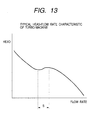
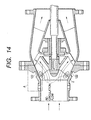
- Fig. 13 shows a typical characteristic curve between head and flow rate in the turbo-machine of the conventional art, including the mixed-flow pump shown in Fig. 14 therein, where the horizontal axis is a parameter indicative of a flow rate, while the vertical axis a parameter indicative of the head.
- the head falls down in a reverse relation to increase of the flow rate in a region of low flow rate, however it rises up following the increase of the flow rate during the time when the flow rate lies within a "S" region (i.e., the characteristic of uprising at the right-hand side).
- the turbo-machine is operated at the flow rate with the characteristic curve of uprising at the right-hand side, a mass of the liquid vibrates by itself, i.e., generating a surging phenomenon.
- the cavitations that comes up to the problem is a phenomenon, where a large number of bubbles occur due to evaporation within the liquid when the pressure of the liquid flowing within the pump is decreased down in the vicinity of the saturated vapor pressure, for example, and those bubbles generated flow within the pump, and/or are collapsed accompanying with recovery of the pressure within the pump. And, such the generation of the cavitations gives damages upon wall surfaces of the impeller, as well as the casing, and it may also cause harmful effects, such as, increase in the vibrations and/or noises, and decrease in the performance thereof, as well.
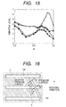
- Fig. 15 shows an experimental result of vibration acceleration, as one representative example of the vibrations and/or noises due to influences of the cavitations, wherein the horizontal axis indicates the flow rate without dimension while the vertical axis the vibration acceleration without dimension thereof.
- black circles ( ⁇ ) in the figure show a flow rate-vibration acceleration curve in a condition where the pump is high in NPSH, in which no groove is formed on the casing thereof, white circles ( ⁇ ) in a condition where the pump is low in NPSH, in which no groove is formed on the casing thereof, black triangles ( ⁇ ) in a condition where the pump is high in NPSH, in which the grooves are formed on the casing in the direction of pressure gradient, and white triangles ( ⁇ ) in a condition where the pump is low in NPSH, in which the grooves are formed on the casing in the direction of pressure gradient, respectively.
- the NPSH means an effective suction head, and it indicates how much higher a total pressure, which the liquid upon a standard surface of the impeller has, than the saturated vapor pressure of that liquid at that temperature. Namely, the lower the NPSH, the nearer to the saturated vapor pressure, i.e., it comes to the condition where the cavitations can easily occur therein.
- the black triangles ( ⁇ ) and white triangles ( ⁇ ) indicating the characteristic curves of the pumps, in which the grooves are formed on the inner surface of the casing in the direction of pressure gradient (i.e., the axial direction)
- the cavitations 4 occurs in an aperture or gap 3 between the blades 122 of the impeller and the casing, as shown in Figs. 16 and 17.
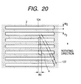
- the Fig. 16 shows a view of the inner surface of the casing, on which the grooves 124 are formed, being expanded schematically
- the Fig. 17 a cross-section view of the blade of the impeller, being cut by a horizontal cross-section perpendicular to a pump axis thereof.
- the cavitations 4 occurring in this gap 3 develops up to the negative pressure side of the blade 122, and a rear end of the cavitations reaches up to the grooves 124 mentioned above.
- an object according to the present invention is to obtain a turbo-machine, having a head-flow rate characteristic of no such the uprising at the right-hand side, at the same time suppressing the increase of the vibrations and/or the noises therein.
- a turbo-type machine comprising: a casing for storing an impeller having blades within an inside thereof; and a plural number of grooves formed on an inner surface of said casing, connecting between an inlet side of the blades and an area on said inner surface where the blades exist, in a direction of pressure gradient of fluid, wherein said grooves are provided in plural from 80 to 150 pieces around a periphery on the inner surface of said casing, and further a total width of said grooves all around the inner surface of said casing is set to be from 30% to 50% with respect to a peripheral length on the inner surface of said casing.
- instable flow of fluid at a terminal end of cavitations, which are generated in a gap at the tip of the blades and enter into the grooves, is guided through a large number of grooves mentioned above, so as to be stabilized therewith, therefore it is possible to mitigate the vibrations and/or noises accompanying with collapse of the cavitations.
- a turbo-type machine comprising: a casing for storing an impeller having blades within an inside thereof; and a plural number of grooves formed on an inner surface of said casing, connecting between an inlet side of the blades and an area on said inner surface where the blades exist, in a direction of pressure gradient of fluid, wherein, a cross-section area of said grooves within the area where the blades exist are set to be larger than that of said grooves within an area outside where the blades exist.
- a turbo-type machine comprising: a casing for storing an impeller having blades within an inside thereof; and a plural number of grooves formed on an inner surface of said casing, connecting between an inlet side of the blades and an area on said inner surface where the blades exist, in a direction of pressure gradient of fluid, wherein said grooves are disposed in unequal distances around a periphery on the inner surface of said casing.
- a turbo-type machine comprising: a casing for storing an impeller having blades within an inside thereof; and a plural number of grooves formed on an inner surface of said casing, connecting between an inlet side of the blades and an area on said inner surface where the blades exist, in a direction of pressure gradient of fluid, wherein one portion of said plural number of grooves are formed to be uniform in a shape of cross-section thereof in an axial direction of said casing, while other portion of said plural number of grooves are formed to be different in the shape of cross-section thereof from that in the area where the blades exist, and said one portion of grooves and said other portion of grooves are disposed alternately.
- the area of cross-section of the groove of the above-mentioned other portion is made larger than that of the grooves of the one portion mentioned above.
- the groove of the one portion is made uniform in the shapes of axial direction thereof
- the groove of the other portion is made smaller in the width and larger in the depth than those of the above in the area where the blades exist, and they are positioned alternately or one by one, thereby making the flow of fluid in the grooves, not uniform, but rather be different to one another.
- the cavitations generated aremade different in shapes thereof, thereby mitigating the vibrations and/or noises when the collapse thereof occurs.
- a turbo-type machine comprising: a casing for storing an impeller having blades within an inside thereof; and a plural number of grooves formed on an inner surface of said casing, connecting between an inlet side of the blades and an area on said inner surface where the blades exist, in a direction of pressure gradient of fluid, wherein openings are drilled on said grooves, each penetrating from a bottom surface thereof through thickness of said casing, in a portion near to a front edge of the blade within the area where no blade exist, and further is provided a ring-like chamber on an outer peripheral surface of said casing, wherein said ring-like chamber is conducted to a position in a stream upper than said penetrating openings in said casing.
- the conducting the grooves to the ring-like chamber on the outer periphery of the casing suppresses the stay of the cavitations, thereby suppressing the generation of the cavitations.
- a turbo-type machine comprising: a casing for storing an impeller having blades within an inside thereof; a suction inlet, being dipped within fluid to be transferred, together with at least said casing; and a plural number of grooves formed on an inner surface of said casing, connecting between an inlet side of the blades and an area on said inner surface where the blades exist, in a direction of pressure gradient of fluid, wherein, openings are drilled on said grooves, each penetrating from a bottom surface thereof through thickness of said casing, in a portion near to a front edge of the blade within the area where no blade exist.
- a turbo-type machine comprising: a casing for storing an impeller having blades within an inside thereof; and a plural number of grooves formed on an inner surface of said casing, connecting between an inlet side of the blades and an area on said inner surface where the blades exist, in a direction of pressure gradient of fluid, wherein said grooves is so set in length thereof within said area where the blades exist, that each of the blades of said impeller intersects with at least one piece or more of said grooves on an inner surface of said casing, irrespective of any position of said blade in a peripheral direction.
- each of the grooves always intersects with at least one piece or more of the blades irrespective of any position of the blades, it is possible to make the difference large between the pressure at a terminal end of the groove at the side of the impeller and the pressure at a start end thereof at the side of suction. With this, the flow flowing through the grooves is increased up, thereby suppressing the cavitations to stay within the grooves, and suppressing the increase of the vibrations and/or noises due to the cavitations.
- a turbo-type machine comprising: a casing for storing an impeller having blades within an inside thereof; and a plural number of grooves formed on an inner surface of said casing, connecting between an inlet side of the blades and an area on said inner surface where the blades exist, in a direction of pressure gradient of fluid, wherein each of said grooves is made in a two-layer structure in the direction of said pressure gradient of fluid, whereby reverse flow from said impeller passes through a layer formed on a side deep with respect to the inner surface of said casing, while main flow directing to said impeller passes through a layer formed on a side shallow with respect to the inner surface of said casing.
- the grooves are constructed so that no collision occurs between the main flow and the reverse flow within the grooves, thereby suppressing the stay of the cavitations within the grooves.
- a turbo-type machine comprising: a casing for storing an impeller having blades within an inside thereof; and a plural number of grooves formed on an inner surface of said casing, connecting between an inlet side of the blades and an area on said inner surface where the blades exist, in a direction of pressure gradient of fluid, wherein a round portion having a radius from 1/4 to 1/2 of thickness of said blade is formed on a ridge defined by a pressure surface and an outer peripheral surface in a direction of thickness thereof, at a tip of each blade of said impeller.
- the round portion having the radius from 1/4 to 1/2 of the thickness of blade is provided at the front edge on the side of pressure surface of the blade, thereby suppressing the cavitations to generate from the front edge of the blade.
- a turbo-type machine comprising: a casing for storing an impeller having blades within an inside thereof; and a plural number of grooves formed on an inner surface of said casing, connecting between an inlet side of the blades and an area on said inner surface where the blades exist, in a direction of pressure gradient of fluid, wherein a fin is formed at each tip of said blades of said impeller in a peripheral direction thereof, extending in a direction on side of a negative pressure surface of said blade by a width from 1/4 to 1 of thickness of the blade.
- the fin having the width from 1/4 to 1 of thickness of the blade is provided at the tip on the negative pressure surface of the blade, thereby not only suppressing leaking flow in the gap at the tip of the blade, but also suppressing the generation of cavitations.
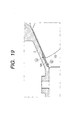
- Fig. 19 shows an enlarged cross-section view of an ordinary mixed-flow pump, and is an enlarged view of a portion of the mixed-flow pump, which is enclosed by a one-dotted chain line therein.
- shallow grooves 124 are formed upon an inner surface of a casing 2, in a direction of pressure gradient of fluid (i.e., the axial direction of the casing), bridging over from a position "a" in a middle of the blade 122 (i.e., the position at terminal end of the groove on a downstream side) up to a position "b" where re-circulation occurs when the flow rate is low (i.e., the position at terminal end of the groove on an upstream side).
- the fluid being increased in pressure by the blades i.e., a liquid such as a water, including fresh water and seawater, etc.
- a liquid such as a water, including fresh water and seawater, etc.
- Figs. 1 (a) and 1 (b) show a turbo-type hydro machine, as the turbo-machine, according to a first embodiment of the present invention.
- a width of each of the grooves formed in a plural number on the inner surface of the casing 2 is set to be nearly equal to the thickness of the above- mentioned blade 122 of the impeller, which is rotatably received within the casing, and a number "n" of pieces of the grooves is indicated by the following equation.
- D an inner diameter of the casing
- Wg a width of the groove
- Pg a distance between the grooves.
- the number of pieces of the plural grooves formed on the inner surface of the above-mentioned casing 2 is set to be as several times large as the ordinary number of the grooves in the conventional art, and an instable flow of the fluid at the terminal end portion of the cavitations, which occur in the gap at a tip of the blade and enter into the grooves, is guided to be stabilized, thereby mitigating the vibrations and/or noises accompanying with the collapse of the cavitations.
- the width Wg of the groove is set to a value being equal to the thickness "t" of the blade on the side of a shroud, or less than that.
- the number "n" of pieces of the grooves is set to one hundred (100), being as about four (4) times large as the number of pieces (28) in the embodiment according to the conventional art. Further, according to the experiments made by the inventors, it is ascertained that desirous effects can be obtained by setting the number of pieces of the grooves formed on the inner surface of the above-mentioned casing 2 within around a range from 80 up to 150 pieces.
- the width of the groove is set to 3 mm, for example, being narrower than 12 mm in the conventional embodiment, being in inverse proportion to the number of pieces of the above-mentioned grooves, and further, accompanying with this, the distance Pg between the grooves can be obtained from the above-mentioned equation (Eq. 1), such as 4.8 mm.
- the thickness of the blade is about 5 mm. It is also ascertained by the experiments made by the inventors, that a total widths of the grooves all around a periphery thereof is desirous to be 30% - 50% of a length of periphery on the inner surface of the casing.
- the width "Wc" of the cavitations 4 generated is nearly equal to the width "Wg" of the groove or greater than that.
- the width "Wg" of said groove is equal to the width of the cavitations or less than that. It is also desirous that the distance "Pg" between the grooves is about same to the width of the groove mentioned above. Accordingly, in the present embodiment, the width "Wc" of the cavitations occurring in the gap at the tip of the blade is set to be nearly equal to the width "Wg" of the groove.
- the mechanism of improvement in the stability of a pump head curve due to the grooves mentioned above is same to that of the conventional art.
- the grooves are narrower in the width "Wg" thereof and is larger in the number of pieces than those of the conventional art.
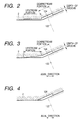
- Fig. 2 shows an enlarged cross-section view of the turbo-type hydro machine according to a second embodiment of the present invention, in particular a portion of the casing 2, on which the grooves are formed on the inner surface side, as the distinctive feature thereof.
- the depth of the grooves 124 at the downstream portion, in the vicinity of an area where the blades exist, is set to be larger than the depth of the grooves at the upstream portion.
- an amount of the flow which is caused by the flow of fluid leaking from a pressure surface of the blade 122 indicated by a two-dotted chain line in the figure directing to the side of negative pressure surface and flows in the reverse direction from the impeller to the upstream in the grooves, comes to be larger than that of the mail flow which tries to flow into the impeller from the upper stream, since the grooves are deep in the depth in the downstream.
- the width of the grooves 124 is constant, and the number of pieces thereof is appropriately selected within a range from about 20 pieces up to about 30 pieces, similar to the conventional ones, and in particular, 28 pieces of the grooves are provided in the present embodiment, for example.
- Fig. 3 shows an enlarged cross-section view of the turbo-type hydro machine according to a third embodiment of the present invention, in particular a portion of the casing 2, on which the grooves are formed.
- the depth of the grooves in the vicinity of an area where the blades exist (at the downstream portion) is set to be larger than the depth of the grooves at the upstream side, and the grooves are formed, so that the depth thereof becomes continuously shallower as it goes from the downstream potion directing to the upstream portion thereof.
- the width of the grooves 124 is constant, and the number of pieces thereof is set at 28 in the present embodiment, in the same manner as mentioned above.
- Fig. 4 shows an enlarged cross-section view of the turbo-type hydro machine according to a fourth embodiment of the present invention, in particular a portion of the casing 2, on which the grooves are formed.
- the grooves 124 are provided only in a tapered portion where the flow passage on a meridian plane enlarges the diameter thereof directing to an outlet on the shroud side.
- it has such the construction that the grooves in parallel or scaled-down flow passages are shortened in the length thereof, in the construction shown in the Fig. 2 or Fig. 3 mentioned above.
- the function and/or effect thereof are/is same to those of the third embodiment, however it has a feature that the machining of the grooves becomes much easier. Further, herein, also the number of pieces of the grooves 124 is set at 28 in the present embodiment, in the same manner as mentioned above.
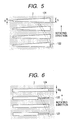
- Fig. 5 schematically shows a plan view of the turbo-type hydro machine according to a fifth embodiment of the present invention, in particular a portion of an inner peripheral surface of the casing 2, on which the grooves 124 are formed, i.e., the expanded inner surface of the casing on which the grooves 124 are formed.
- the width 5 of the grooves in the area where the blades 122 exist is made larger than the width 6 of the grooves at the upstream portion where no blade exists, and a portion between them is formed in a taper-like, so the groove changes in the width thereof continuously.
- the depth of the grooves 124 is constant, therefore the cross-section area, in particular the cross-section area of the groove 124 in the area where the blades exist is larger than that of the grooves 124 in the upstream area where no blade exists.
- the number of pieces the grooves 124 is set at 28 in the present embodiment, in the same manner as mentioned above. Further, the function and/or effect thereof are/is same to those/that of the third embodiment shown in the Fig. 3 mentioned above. Also, in the present embodiment, it is possible to bring the amount of flow to be large, flowing through the grooves 124 formed on the inner peripheral surface of the casing 2 mentioned above, therefore the function of stabilizing the head curve is much larger than that of the other embodiments mentioned in the above.
- Fig. 6 shows the turbo-type hydro machine according to a sixth embodiment of the present invention.
- the inner surface of the casing, on which the grooves 124 are formed is schematically shown under the condition of being expanded.
- the groove 124 is constant in a form or shape of cross-section thereof in the upstream area where no blade exists, while the groove 125 is narrow in the width Wg in the area where the blades exist (the downstream area) neighboring thereto.
- the depth of those grooves 124 and 125 is constant.
- the number of pieces of the grooves 124 is set at 28, in the same manner as mentioned above.
- narrowing the width Wg of the grooves in the area where the blades exist brings about an effect of reducing the strength in collapse of the generated cavitations, in the same manner as in the first embodiment shown in the Fig. 1 mentioned above.
- the grooves 125 having the narrow width Wg and the grooves 124 having the wide width Wg are disposed alternately, thereby obtaining the stabilization of the head curve while also maintaining the reverse flow amount at the same time.
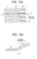
- Figs. 7 (a) and 7 (b) show the turbo-type hydro machine according to a seventh embodiment of the present invention. Further, the Fig. 7 (a) schematically shows the casing, on which the grooves are provided upon the inner peripheral surface thereof, being expanded, while the Fig. 7 (b) is the cross-section view for showing the structure of the casing, on which the grooves mentioned above are provided.
- this embodiment has such the structure as shown by the embodiment 2 in the Fig. 2 mentioned above, i.e., in the structure, in which the grooves are made large in the depth thereof in the area where the blades exist (the downstream portion), there are further provided deep grooves 126 extending therefrom, having a narrow width in the downstream portion.
- the number of pieces the grooves 124 is set at 28, in the same manner as mentioned above.
- the number of pieces of the grooves 124 formed in the area where the blades exist (the downstream area) on the inner peripheral surface of the casing is about 28, being same in the conventional one, however it should not be restricted therewith, according to the present invention, namely in the same manner as shown in the Fig.
- the number of pieces of the grooves 124 it is possible to set the number of pieces of the grooves 124 to be as several times large as that of the above, for example, about one hundred (100) pieces, being as roughly four (4) times large as that (within a range from 80 pieces to 150 pieces), and with this, the cavitations can be prevented from the generation thereof, more effectively, or can be suppressed thereby.
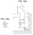
- Figs. 8 (a) and 8 (b) show the turbo-type hydro machine according to an eighth embodiment of the present invention, and as shown in the Fig. 8 (a), it is applied into a stand-type pump, in which a bell mouth and an impeller portion thereof are installed within a suction water tank 200.
- this stand-type pump as shown in the Fig.
- an opening or bore 127 is drilled at a position near to a front edge of the blade 122 where the cavitations bubbles stay, penetrating through the thickness of the casing 2, in each of the grooves 124 provided on the inner peripheral surface of the casing 2 in the axial direction thereof (i.e., the direction of pressure gradient of the fluid), thereby conducting the water within said the grooves 124 with that in the suction water tank 200 through a bottom surface of the groove.
- the diameter of this opening is so set that the total cross-section area of the openings is equal or less than 1% of the cross-section area at the inlet of the impeller, in the direction perpendicular to the axial direction thereof.
- the number of pieces the grooves 124 is set at 28, in the same manner as mentioned above.
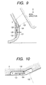
- Fig. 9 shows the turbo-type hydro machine according to a ninth embodiment of the present invention.
- the bell mouth and the impeller portion are installed within the suction water tank, in the same manner as in the eighth embodiment mentioned above, i.e., being applied into the stand-type pump.
- an opening or bore 128 is drilled at a position near to the front edge of the blade 122 where the cavitations bubbles stay, penetrating through the thickness of the casing 2, in each of the grooves 124 formed on the inner peripheral surface of the casing 2 in the axial direction thereof (i.e., the direction of pressure gradient of the fluid), and further a second opening or bore 129 is drilled at an upstream position upper than the first opening 128 mentioned above.
- the position to be formed with this second opening 129 is preferable, in particular, on a wall surface of the casing 2 of a throat portion where the flow passage is at the minimum in the cross-section area, in the axial direction of the casing (i.e., the direction of pressure gradient in fluid).
- a cover 130 covering over an outer periphery of the casing 2 in a ring-like manner, thereby forming a chamber 131 of a ring-like shape between this cover 130 and the casing 2.
- this chamber 131 is constructed, so that it is conducted with a different position on an inner periphery of the casing 2 through the first opening 128 and the second opening 129.
- the number of pieces the grooves 124 is set at 28, in the same manner as mentioned above.
- the stationary pressure in the vicinity of the first opening 128 comes to be higher than the pressure near to the saturated vapor pressure, thereby suppressing the development of the cavitations, or making the cavitations small, therefore the vibrations and/or noises accompanying with the collapse thereof also come to be small.
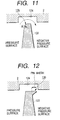
- Fig. 10 shows the turbo-type hydro machine according to the tenth embodiment of the present invention, in particular, the enlarged cross-section view of a portion of the casing 2, on which the plural numbers of grooves are formed on the inner peripheral surface thereof.
- Each of the grooves according to the present embodiment, as apparent from the figure, is provided with a thin partition 134 in a central portion in the longitudinal direction thereof, and with this, the groove mentioned above has a two-layer structure, being made up with a first flow passage 132 being large in the distance from the axis of the pump (i.e., at deep side) and a second flow passage 133 being small in the distance from the axis of the pump (i.e., at shallow side).
- the partition plate 134 is not provided at the both ends of the groove, therefore, this groove has the flow passage of a single layer at the both end portions thereof.
- the number of pieces the grooves 124 is set at 28, in the same manner as mentioned above.
- Figs. 11 and 12 attached show an eleventh embodiment and a twelfth embodiment according to the present invention.
- the embodiments mentioned in the above mainly relate to the number of pieces of the grooves and the form thereof, but the present embodiments shown in the Figs. 11 and 12 relate to a shape of the tip on the blade of the impeller.
- the Fig. 11 shows the g-g cross-section in the Fig. 16 mentioned above, schematically showing the inner surface of the casing being expanded, on which the grooves 124 are provided.
- the side of pressure surface at the tip of the blade 122 of the impeller not defines a sharp edge (about right angle) with respect to an outer peripheral surface like the blade of the conventional art, but shapes a round form 135 having a radius R from 1/4 to 1/2 of the thickness of the blade. With such the round form, no sharp ridgeline is defined by the pressure surface and the outer peripheral surface, at the tip of the blade 122.
- Fig. 12 shows g-g cross-section in the Fig. 16, in the same manner as in the Fig. 11.
- a fin 136 having the width from 1/4 to 1 of the blade thickness over the total length (periphery) of the blade 122, or bridging over from the front edge to the central portion of the blade in the peripheral direction thereof.
- the cross-sectional shape of this fin 136 has an outer periphery portion forming a surface extending to the outer periphery of the blade 122, while the thickness of the fin 136 is uniform from the tip to the base thereof, or is large at the base and is changed (i.e., is decreased) continuously in the thickness between them.
- the length of the space defined between the outer peripheral portion (surface) of the blade 122 and the casing 2 at the stationary side comes to be longer by the length of the fin 136 mentioned above.
- the flow rate flowing in this gap is in proportional to the pressure difference between the outlet and the inlet of the gap defined, or the square root thereof, on the other hand it is in inverse proportional to the length of the space. Accordingly, with such the structure, the fluid flowing in the gap at the tip of the blade 122 is decreased down in the velocity thereof, and the decrease in the stationary pressure within the said gap also comes to be small. With this, the generation of the cavitations bubbles comes to be small in the gap, and also the vibrations and/or noises accompanying with the cavitations bubbles come to be small.
- the turbo-type machine having such the construction, that the characteristic curve of the head-flow rate uprising at the right-hand side is removed by means of the grooves, being provided in plural number on the inner peripheral surface of the casing, wherein the cavitations, generated in the gap at the tip of blade accompanying with the above-mentioned grooves provided in plural number thereof, is suppressed to stay within the grooves, or the generation of cavitations itself is suppressed within the gap, therefore it is possible to achieve a superior effect of reducing the vibrations and/or noises which occur in the turbo-type machine, accompanying with the collapse of the cavitations bubbles.
Applications Claiming Priority (2)
| Application Number | Priority Date | Filing Date | Title |
|---|---|---|---|
| JP2000286110 | 2000-09-20 | ||
| JP2000286110A JP3862137B2 (ja) | 2000-09-20 | 2000-09-20 | ターボ形水力機械 |
Publications (3)
| Publication Number | Publication Date |
|---|---|
| EP1191231A2 true EP1191231A2 (fr) | 2002-03-27 |
| EP1191231A3 EP1191231A3 (fr) | 2006-01-18 |
| EP1191231B1 EP1191231B1 (fr) | 2008-05-14 |
Family
ID=18770079
Family Applications (1)
| Application Number | Title | Priority Date | Filing Date |
|---|---|---|---|
| EP01106933A Expired - Lifetime EP1191231B1 (fr) | 2000-09-20 | 2001-03-20 | Turbomachines |
Country Status (4)
| Country | Link |
|---|---|
| US (1) | US6540482B2 (fr) |
| EP (1) | EP1191231B1 (fr) |
| JP (1) | JP3862137B2 (fr) |
| DE (1) | DE60133976D1 (fr) |
Cited By (6)
| Publication number | Priority date | Publication date | Assignee | Title |
|---|---|---|---|---|
| WO2004055381A1 (fr) * | 2002-12-17 | 2004-07-01 | Ksb Aktiengesellschaft | Conduite d'aspiration |
| NL2003467C2 (nl) * | 2009-09-10 | 2011-03-14 | Nijhuis Pompen B V | Visvriendelijke pomp- of turbineinrichting. |
| CN101743405B (zh) * | 2008-02-29 | 2012-08-22 | 三菱重工业株式会社 | 离心压缩机 |
| FR2989742A1 (fr) * | 2012-04-19 | 2013-10-25 | Snecma | Carter de compresseur a cavites a forme amont optimisee |
| WO2016082916A1 (fr) * | 2014-11-25 | 2016-06-02 | Ihi Charging Systems International Gmbh | Compresseur pour turbocompresseur à gaz d'échappement |
| CN105673553A (zh) * | 2016-03-18 | 2016-06-15 | 江苏大学 | 一种斜流泵 |
Families Citing this family (6)
| Publication number | Priority date | Publication date | Assignee | Title |
|---|---|---|---|---|
| JP3872966B2 (ja) * | 2001-06-29 | 2007-01-24 | 株式会社日立プラントテクノロジー | 軸流形流体機械 |
| DE102008052401A1 (de) * | 2008-10-21 | 2010-04-22 | Rolls-Royce Deutschland Ltd & Co Kg | Strömungsarbeitsmaschine mit Laufspalteinzug |
| US8337160B2 (en) * | 2009-10-19 | 2012-12-25 | Toyota Motor Engineering & Manufacturing North America, Inc. | High efficiency turbine system |
| JP5980671B2 (ja) * | 2012-12-18 | 2016-08-31 | 三菱重工業株式会社 | 回転機械 |
| US10539154B2 (en) * | 2014-12-10 | 2020-01-21 | General Electric Company | Compressor end-wall treatment having a bent profile |
| GB2545412B (en) | 2015-12-11 | 2018-06-06 | Dyson Technology Ltd | A hair care appliance comprising a motor |
Citations (4)
| Publication number | Priority date | Publication date | Assignee | Title |
|---|---|---|---|---|
| US4086022A (en) * | 1975-09-25 | 1978-04-25 | Rolls-Royce Limited | Gas turbine engine with improved compressor casing for permitting higher air flow and pressure ratios before surge |
| US4767266A (en) * | 1984-02-01 | 1988-08-30 | Societe Nationale D'etude Et De Construction De Moteurs D'aviation (Snecma) | Sealing ring for an axial compressor |
| US4781530A (en) * | 1986-07-28 | 1988-11-01 | Cummins Engine Company, Inc. | Compressor range improvement means |
| EP0754864A1 (fr) * | 1995-07-18 | 1997-01-22 | Ebara Corporation | Turbomachine |
Family Cites Families (10)
| Publication number | Priority date | Publication date | Assignee | Title |
|---|---|---|---|---|
| GB2017228B (en) * | 1977-07-14 | 1982-05-06 | Pratt & Witney Aircraft Of Can | Shroud for a turbine rotor |
| US4212585A (en) * | 1978-01-20 | 1980-07-15 | Northern Research And Engineering Corporation | Centrifugal compressor |
| GB2245312B (en) * | 1984-06-19 | 1992-03-25 | Rolls Royce Plc | Axial flow compressor surge margin improvement |
| US4961686A (en) * | 1989-02-17 | 1990-10-09 | General Electric Company | F.O.D.-resistant blade |
| RU2034175C1 (ru) * | 1993-03-11 | 1995-04-30 | Центральный институт авиационного моторостроения им.П.И.Баранова | Турбокомпрессор |
| US5607284A (en) * | 1994-12-29 | 1997-03-04 | United Technologies Corporation | Baffled passage casing treatment for compressor blades |
| DE19510811A1 (de) * | 1995-03-24 | 1996-09-26 | Klein Schanzlin & Becker Ag | Faser abweisende Wandflächengestaltung |
| GB9823840D0 (en) * | 1998-10-30 | 1998-12-23 | Rolls Royce Plc | Bladed ducting for turbomachinery |
| US6155778A (en) * | 1998-12-30 | 2000-12-05 | General Electric Company | Recessed turbine shroud |
| US6234747B1 (en) * | 1999-11-15 | 2001-05-22 | General Electric Company | Rub resistant compressor stage |
-
2000
- 2000-09-20 JP JP2000286110A patent/JP3862137B2/ja not_active Expired - Fee Related
-
2001
- 2001-03-20 US US09/811,495 patent/US6540482B2/en not_active Expired - Lifetime
- 2001-03-20 DE DE60133976T patent/DE60133976D1/de not_active Expired - Lifetime
- 2001-03-20 EP EP01106933A patent/EP1191231B1/fr not_active Expired - Lifetime
Patent Citations (4)
| Publication number | Priority date | Publication date | Assignee | Title |
|---|---|---|---|---|
| US4086022A (en) * | 1975-09-25 | 1978-04-25 | Rolls-Royce Limited | Gas turbine engine with improved compressor casing for permitting higher air flow and pressure ratios before surge |
| US4767266A (en) * | 1984-02-01 | 1988-08-30 | Societe Nationale D'etude Et De Construction De Moteurs D'aviation (Snecma) | Sealing ring for an axial compressor |
| US4781530A (en) * | 1986-07-28 | 1988-11-01 | Cummins Engine Company, Inc. | Compressor range improvement means |
| EP0754864A1 (fr) * | 1995-07-18 | 1997-01-22 | Ebara Corporation | Turbomachine |
Cited By (13)
| Publication number | Priority date | Publication date | Assignee | Title |
|---|---|---|---|---|
| US7798772B2 (en) | 2002-12-17 | 2010-09-21 | Ksb Aktiengesellschaft | Centrifugal pump intake channel |
| WO2004055381A1 (fr) * | 2002-12-17 | 2004-07-01 | Ksb Aktiengesellschaft | Conduite d'aspiration |
| CN101743405B (zh) * | 2008-02-29 | 2012-08-22 | 三菱重工业株式会社 | 离心压缩机 |
| EP2295808B1 (fr) | 2009-09-10 | 2016-06-08 | Nijhuis Pompen BV | Turbine ou pompe hydraulique sans danger pour les poissons |
| NL2003467C2 (nl) * | 2009-09-10 | 2011-03-14 | Nijhuis Pompen B V | Visvriendelijke pomp- of turbineinrichting. |
| EP2295808B2 (fr) † | 2009-09-10 | 2019-11-20 | Nijhuis Pompen BV | turbine ou pompe hydraulique sans danger pour les poissons |
| US9638213B2 (en) | 2012-04-19 | 2017-05-02 | Snecma | Compressor casing comprising cavities having an optimised upstream shape |
| WO2013156726A3 (fr) * | 2012-04-19 | 2014-01-09 | Snecma | Carter de compresseur á cavités a forme amont optimisée |
| FR2989742A1 (fr) * | 2012-04-19 | 2013-10-25 | Snecma | Carter de compresseur a cavites a forme amont optimisee |
| WO2016082916A1 (fr) * | 2014-11-25 | 2016-06-02 | Ihi Charging Systems International Gmbh | Compresseur pour turbocompresseur à gaz d'échappement |
| CN107002700A (zh) * | 2014-11-25 | 2017-08-01 | Ihi供应系统国际有限责任公司 | 用于废气涡轮增压器的压缩机 |
| US10400789B2 (en) | 2014-11-25 | 2019-09-03 | Charging Systems International Gmbh | Compressor for an exhaust gas turbocharger |
| CN105673553A (zh) * | 2016-03-18 | 2016-06-15 | 江苏大学 | 一种斜流泵 |
Also Published As
| Publication number | Publication date |
|---|---|
| EP1191231B1 (fr) | 2008-05-14 |
| US20030031559A1 (en) | 2003-02-13 |
| DE60133976D1 (de) | 2008-06-26 |
| JP2002098099A (ja) | 2002-04-05 |
| JP3862137B2 (ja) | 2006-12-27 |
| US6540482B2 (en) | 2003-04-01 |
| EP1191231A3 (fr) | 2006-01-18 |
Similar Documents
| Publication | Publication Date | Title |
|---|---|---|
| US6290458B1 (en) | Turbo machines | |
| JP4295611B2 (ja) | 流れ安定化装置 | |
| US6540482B2 (en) | Turbo-type machines | |
| US7207767B2 (en) | Inducer, and inducer-equipped pump | |
| US7896618B2 (en) | Centrifugal compressing apparatus | |
| EP1270953B1 (fr) | Machine hydraulique à courant axial | |
| US6527509B2 (en) | Turbo machines | |
| KR100554854B1 (ko) | 혼류 펌프 | |
| EP1069315B1 (fr) | Turbomachines | |
| JP5067928B2 (ja) | 軸流ターボ機械 | |
| US6302643B1 (en) | Turbo machines | |
| EP1134427A1 (fr) | Turbo machines | |
| JP4209362B2 (ja) | 遠心圧縮機 | |
| JP2005240727A (ja) | 衝動型軸流タービン | |
| KR100539345B1 (ko) | 날개 입구 재순환류 및 날개 선회 실속을 억제한 터보 기계 | |
| JP4079740B2 (ja) | 軸流形流体機械 | |
| JP2003521612A (ja) | 設備の建屋と設備の運転方法 | |
| JP7306971B2 (ja) | ポンプ | |
| JP2844966B2 (ja) | 渦流ポンプ | |
| JP4312720B2 (ja) | 遠心ポンプ | |
| JPS5813041Y2 (ja) | 蒸気タ−ビンの作動流体漏洩防止装置 |
Legal Events
| Date | Code | Title | Description |
|---|---|---|---|
| PUAI | Public reference made under article 153(3) epc to a published international application that has entered the european phase |
Free format text: ORIGINAL CODE: 0009012 |
|
| 17P | Request for examination filed |
Effective date: 20010320 |
|
| AK | Designated contracting states |
Kind code of ref document: A2 Designated state(s): AT BE CH CY DE DK ES FI FR GB GR IE IT LI LU MC NL PT SE TR |
|
| AX | Request for extension of the european patent |
Free format text: AL;LT;LV;MK;RO;SI |
|
| PUAL | Search report despatched |
Free format text: ORIGINAL CODE: 0009013 |
|
| AK | Designated contracting states |
Kind code of ref document: A3 Designated state(s): AT BE CH CY DE DK ES FI FR GB GR IE IT LI LU MC NL PT SE TR |
|
| AX | Request for extension of the european patent |
Extension state: AL LT LV MK RO SI |
|
| AKX | Designation fees paid |
Designated state(s): DE FR GB |
|
| RAP1 | Party data changed (applicant data changed or rights of an application transferred) |
Owner name: HITACHI PLANT TECHNOLOGIES, LTD. Owner name: KUROKAWA, JUNICHI |
|
| GRAP | Despatch of communication of intention to grant a patent |
Free format text: ORIGINAL CODE: EPIDOSNIGR1 |
|
| GRAS | Grant fee paid |
Free format text: ORIGINAL CODE: EPIDOSNIGR3 |
|
| GRAA | (expected) grant |
Free format text: ORIGINAL CODE: 0009210 |
|
| AK | Designated contracting states |
Kind code of ref document: B1 Designated state(s): DE FR GB |
|
| REG | Reference to a national code |
Ref country code: GB Ref legal event code: FG4D |
|
| REF | Corresponds to: |
Ref document number: 60133976 Country of ref document: DE Date of ref document: 20080626 Kind code of ref document: P |
|
| PLBE | No opposition filed within time limit |
Free format text: ORIGINAL CODE: 0009261 |
|
| STAA | Information on the status of an ep patent application or granted ep patent |
Free format text: STATUS: NO OPPOSITION FILED WITHIN TIME LIMIT |
|
| 26N | No opposition filed |
Effective date: 20090217 |
|
| REG | Reference to a national code |
Ref country code: DE Ref legal event code: R082 Ref document number: 60133976 Country of ref document: DE Representative=s name: V. FUENER EBBINGHAUS FINCK HANO, DE |
|
| REG | Reference to a national code |
Ref country code: GB Ref legal event code: 732E Free format text: REGISTERED BETWEEN 20140220 AND 20140226 |
|
| REG | Reference to a national code |
Ref country code: DE Ref legal event code: R082 Ref document number: 60133976 Country of ref document: DE Representative=s name: V. FUENER EBBINGHAUS FINCK HANO, DE Effective date: 20140218 Ref country code: DE Ref legal event code: R081 Ref document number: 60133976 Country of ref document: DE Owner name: KUROKAWA, JUNICHI, JP Free format text: FORMER OWNER: HITACHI PLANT TECHNOLOGIES, LTD,JUNICHI KUROKAWA, , JP Effective date: 20140218 Ref country code: DE Ref legal event code: R081 Ref document number: 60133976 Country of ref document: DE Owner name: HITACHI, LTD., JP Free format text: FORMER OWNER: HITACHI PLANT TECHNOLOGIES, LTD,JUNICHI KUROKAWA, , JP Effective date: 20140218 Ref country code: DE Ref legal event code: R081 Ref document number: 60133976 Country of ref document: DE Owner name: KUROKAWA, JUNICHI, YOKOHAMA, JP Free format text: FORMER OWNER: HITACHI PLANT TECHNOLOGIES, LTD,JUNICHI KUROKAWA, , JP Effective date: 20140218 Ref country code: DE Ref legal event code: R081 Ref document number: 60133976 Country of ref document: DE Owner name: HITACHI, LTD., JP Free format text: FORMER OWNERS: HITACHI PLANT TECHNOLOGIES, LTD., TOKIO, JP; KUROKAWA, JUNICHI, YOKOHAMA, KANAGAWA, JP Effective date: 20140218 Ref country code: DE Ref legal event code: R081 Ref document number: 60133976 Country of ref document: DE Owner name: KUROKAWA, JUNICHI, YOKOHAMA, JP Free format text: FORMER OWNERS: HITACHI PLANT TECHNOLOGIES, LTD., TOKIO, JP; KUROKAWA, JUNICHI, YOKOHAMA, KANAGAWA, JP Effective date: 20140218 |
|
| REG | Reference to a national code |
Ref country code: GB Ref legal event code: 732E Free format text: REGISTERED BETWEEN 20140313 AND 20140319 |
|
| REG | Reference to a national code |
Ref country code: FR Ref legal event code: TQ Owner name: JUNICHI KUROKAWA, JP Effective date: 20140612 Ref country code: FR Ref legal event code: TQ Owner name: HITACHI, LTD., JP Effective date: 20140612 |
|
| REG | Reference to a national code |
Ref country code: FR Ref legal event code: PLFP Year of fee payment: 16 |
|
| PGFP | Annual fee paid to national office [announced via postgrant information from national office to epo] |
Ref country code: DE Payment date: 20160315 Year of fee payment: 16 |
|
| PGFP | Annual fee paid to national office [announced via postgrant information from national office to epo] |
Ref country code: FR Payment date: 20160208 Year of fee payment: 16 Ref country code: GB Payment date: 20160316 Year of fee payment: 16 |
|
| REG | Reference to a national code |
Ref country code: DE Ref legal event code: R119 Ref document number: 60133976 Country of ref document: DE |
|
| GBPC | Gb: european patent ceased through non-payment of renewal fee |
Effective date: 20170320 |
|
| REG | Reference to a national code |
Ref country code: FR Ref legal event code: ST Effective date: 20171130 |
|
| PG25 | Lapsed in a contracting state [announced via postgrant information from national office to epo] |
Ref country code: FR Free format text: LAPSE BECAUSE OF NON-PAYMENT OF DUE FEES Effective date: 20170331 Ref country code: DE Free format text: LAPSE BECAUSE OF NON-PAYMENT OF DUE FEES Effective date: 20171003 |
|
| PG25 | Lapsed in a contracting state [announced via postgrant information from national office to epo] |
Ref country code: GB Free format text: LAPSE BECAUSE OF NON-PAYMENT OF DUE FEES Effective date: 20170320 |