EP1190784A2 - Verfahren zur Herstellung eines Rohres mit partiell unterschiedlichen Wandstärken - Google Patents
Verfahren zur Herstellung eines Rohres mit partiell unterschiedlichen Wandstärken Download PDFInfo
- Publication number
- EP1190784A2 EP1190784A2 EP01119590A EP01119590A EP1190784A2 EP 1190784 A2 EP1190784 A2 EP 1190784A2 EP 01119590 A EP01119590 A EP 01119590A EP 01119590 A EP01119590 A EP 01119590A EP 1190784 A2 EP1190784 A2 EP 1190784A2
- Authority
- EP
- European Patent Office
- Prior art keywords
- mandrel
- tube
- pipe
- recess
- drawing ring
- Prior art date
- Legal status (The legal status is an assumption and is not a legal conclusion. Google has not performed a legal analysis and makes no representation as to the accuracy of the status listed.)
- Withdrawn
Links
Images


Classifications
-
- B—PERFORMING OPERATIONS; TRANSPORTING
- B21—MECHANICAL METAL-WORKING WITHOUT ESSENTIALLY REMOVING MATERIAL; PUNCHING METAL
- B21C—MANUFACTURE OF METAL SHEETS, WIRE, RODS, TUBES, PROFILES OR LIKE SEMI-MANUFACTURED PRODUCTS OTHERWISE THAN BY ROLLING; AUXILIARY OPERATIONS USED IN CONNECTION WITH METAL-WORKING WITHOUT ESSENTIALLY REMOVING MATERIAL
- B21C37/00—Manufacture of metal sheets, rods, wire, tubes, profiles or like semi-manufactured products, not otherwise provided for; Manufacture of tubes of special shape
- B21C37/06—Manufacture of metal sheets, rods, wire, tubes, profiles or like semi-manufactured products, not otherwise provided for; Manufacture of tubes of special shape of tubes or metal hoses; Combined procedures for making tubes, e.g. for making multi-wall tubes
- B21C37/15—Making tubes of special shape; Making tube fittings
- B21C37/16—Making tubes with varying diameter in longitudinal direction
-
- B—PERFORMING OPERATIONS; TRANSPORTING
- B21—MECHANICAL METAL-WORKING WITHOUT ESSENTIALLY REMOVING MATERIAL; PUNCHING METAL
- B21C—MANUFACTURE OF METAL SHEETS, WIRE, RODS, TUBES, PROFILES OR LIKE SEMI-MANUFACTURED PRODUCTS OTHERWISE THAN BY ROLLING; AUXILIARY OPERATIONS USED IN CONNECTION WITH METAL-WORKING WITHOUT ESSENTIALLY REMOVING MATERIAL
- B21C1/00—Manufacture of metal sheets, wire, rods, tubes or like semi-manufactured products by drawing
- B21C1/16—Metal drawing by machines or apparatus in which the drawing action is effected by means other than drums, e.g. by a longitudinally-moved carriage pulling or pushing the work or stock for making metal sheets, rods or tubes
- B21C1/22—Metal drawing by machines or apparatus in which the drawing action is effected by means other than drums, e.g. by a longitudinally-moved carriage pulling or pushing the work or stock for making metal sheets, rods or tubes specially adapted for making tubular articles
- B21C1/24—Metal drawing by machines or apparatus in which the drawing action is effected by means other than drums, e.g. by a longitudinally-moved carriage pulling or pushing the work or stock for making metal sheets, rods or tubes specially adapted for making tubular articles by means of mandrels
-
- B—PERFORMING OPERATIONS; TRANSPORTING
- B21—MECHANICAL METAL-WORKING WITHOUT ESSENTIALLY REMOVING MATERIAL; PUNCHING METAL
- B21C—MANUFACTURE OF METAL SHEETS, WIRE, RODS, TUBES, PROFILES OR LIKE SEMI-MANUFACTURED PRODUCTS OTHERWISE THAN BY ROLLING; AUXILIARY OPERATIONS USED IN CONNECTION WITH METAL-WORKING WITHOUT ESSENTIALLY REMOVING MATERIAL
- B21C3/00—Profiling tools for metal drawing; Combinations of dies and mandrels for metal drawing
Definitions
- the present invention relates to a method for producing a tube partially different wall thicknesses.
- metal sheets have so far been welded together then formed into a tube and also welded so that a partial reinforcement in the areas that should be thickened.
- the present invention has for its object a method of the generic type Art to train so that a simple, all requirements manufacturing is possible without impairing the material properties.
- This method is particularly characterized by its simplicity with regard to the implementation.
- the individual process steps can be done in one continuous process can be carried out, so that especially in the automotive industry high quantities can be easily produced.
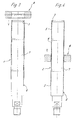
- the outer tube is stretched, the original wall being pressed into the recess of the mandrel and the subsequent areas is diluted with thinning the wall thickness.
- the lesser Wall thickness is determined by the distance between the clear Diameter of the drawing ring and the largest outside diameter of the mandrel.
- the stretching of the material causes strain hardening, particularly in the thin-walled area Area that can be defined according to the functional requirements can.
- the invention offers the possibility of several sections of the outer tube edit accordingly, which in addition to the advantages mentioned also results in a weight saving, which is particularly remarkable as Especially in the automotive industry, special efforts are made to everywhere minimize the weight of components.
- tubes with smooth outer surfaces are used in so-called hydroforming used in which the tube is surrounded by an outer shape is and so pressurized inside by means of a pressure medium is that the wall of the tube fits the contour of the outer shape.
- a gradation-free, smooth surface of the pipe is required.
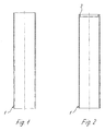
- FIG. 1 an output pipe 1 is shown, which is initially connected to one end inwardly directed stop 3 is formed ( Figure 2).
- This mandrel 6, which is as circular in cross section as the outlet tube 1, is approximately in the middle area with a partially extending in the axial direction Provide depression, the depth of which is at most the wall thickness of the outlet pipe 1 equivalent.
- the regions of the mandrel 6 adjoining the recess 7 on both sides correspond the inside diameter of the inside diameter of the outlet pipe 1.
- FIG. 7 shows the finished tube 2.
Landscapes
- Engineering & Computer Science (AREA)
- Mechanical Engineering (AREA)
- Shaping Metal By Deep-Drawing, Or The Like (AREA)
- Metal Extraction Processes (AREA)
- Shaping Of Tube Ends By Bending Or Straightening (AREA)
- Forging (AREA)
Abstract
Description
- Fig. 1-7
- ein erfindungsgemäßes Rohr in einem Längsschnitt jeweils in verschiedenen Verfahrensschritten dargestellt.
Claims (8)
- Verfahren zur Herstellung eines Rohres mit partiell unterschiedlichen Wandstärken, dadurch gekennzeichnet, daß in ein Ausgangsrohr (1) ein mit mindestens einer außenseitigen, beidseitig in axialer Richtung begrenzten Vertiefung (7) versehener Dorn (6) eingeschoben, anschließend ein Ziehring (8), dessen lichter Durchmesser kleiner ist als der Außendurchmesser des Ausgangsrohres (1), über das gegenüber dem Dorn (6) in Ziehrichtung gehaltene Rohr (2) gezogen wird, wobei ein Teil des Rohres (2) in die Vertiefung (7) gedrückt wird und danach der Dorn (6) unter radialem Herausdrücken der in der Vertiefung einliegenden Rohrwandung aus dem Rohr (2) herausgezogen wird.
- Verfahren nach Anspruch 1, dadurch gekennzeichnet, daß nach dem Herausziehen des Dornes (6) der Ziehring (8) unter Eindrücken der radial vorstehenden Rohrwandung über das Rohr (2) gezogen wird.
- Verfahren nach Anspruch 1, dadurch gekennzeichnet, daß vor dem Einschieben des Dornes (6) in das Ausgangsrohr (1) an einer Endseite des Ausgangsrohres (1) ein sich radial nach innen erstreckender Anschlag (3) angeformt wird.
- Verfahren nach Anspruch 3, dadurch gekennzeichnet, daß der Anschlag (3) im Bereich der Einschubseite des Ziehringes (8) angeformt wird.
- Vorrichtung zur Durchführung des Verfahrens nach Anspruch 1, dadurch gekennzeichnet, daß ein in ein Ausgangsrohr (1) einschiebbarer Dorn vorgesehen ist, der mindestens eine beidseitig in axialer Richtung begrenzte Vertiefung (7) aufweist und mit einem Ziehring (8) in Wirkverbindung bringbar ist, dessen lichter Durchmesser kleiner ist als der Außendurchmesser des Ausgangsrohres (1), wobei der Abstand zwischen dem lichten Radius des Ziehrings (8) und dem Radius des Dornes (6) kleiner ist als die Wandstärke des Ausgangsrohres (1).
- Vorrichtung nach Anspruch 5, dadurch gekennzeichnet, daß die Tiefe der Vertiefung (7) maximal der Wandstärke des Ausgangsrohres (1) entspricht.
- Vorrichtung nach Anspruch 5, dadurch gekennzeichnet, daß eine Mehrzahl von über den Umfang des Dornes (6) verteilten, sich axial erstreckenden und parallel und mit Abstand zueinander verlaufenden Vertiefungen vorgesehen ist.
- Vorrichtung nach Anspruch 7, dadurch gekennzeichnet, daß die Vertiefungen unterschiedlich ausgebildet sind.
Applications Claiming Priority (2)
| Application Number | Priority Date | Filing Date | Title |
|---|---|---|---|
| DE10047231A DE10047231C1 (de) | 2000-09-23 | 2000-09-23 | Verfahren und Vorrichtung zur Herstellung eines Rohres mit partiell unterschiedlichen Wandstärken |
| DE10047231 | 2000-09-23 |
Publications (2)
| Publication Number | Publication Date |
|---|---|
| EP1190784A2 true EP1190784A2 (de) | 2002-03-27 |
| EP1190784A3 EP1190784A3 (de) | 2003-11-19 |
Family
ID=7657395
Family Applications (1)
| Application Number | Title | Priority Date | Filing Date |
|---|---|---|---|
| EP01119590A Withdrawn EP1190784A3 (de) | 2000-09-23 | 2001-08-16 | Verfahren zur Herstellung eines Rohres mit partiell unterschiedlichen Wandstärken |
Country Status (3)
| Country | Link |
|---|---|
| US (1) | US20020043089A1 (de) |
| EP (1) | EP1190784A3 (de) |
| DE (1) | DE10047231C1 (de) |
Cited By (2)
| Publication number | Priority date | Publication date | Assignee | Title |
|---|---|---|---|---|
| EP1835199A3 (de) * | 2006-03-14 | 2007-11-07 | Muhr und Bender KG | Federbeinrohr aus flexibel gewalztem Blech |
| WO2014067581A1 (de) | 2012-11-02 | 2014-05-08 | Schmittergroup Ag | Verfahren zur herstellung unterschiedlicher wanddicken eines behälterrohres |
Families Citing this family (10)
| Publication number | Priority date | Publication date | Assignee | Title |
|---|---|---|---|---|
| US6309195B1 (en) * | 1998-06-05 | 2001-10-30 | Halliburton Energy Services, Inc. | Internally profiled stator tube |
| US6973759B2 (en) | 2001-08-28 | 2005-12-13 | Cardinal Ig Company | Methods and apparatus for providing information at the point of use for an insulating glass unit |
| US7431317B2 (en) * | 2002-08-05 | 2008-10-07 | Giant Manufacturing Co., Ltd. | Bicycle frame part having a disproportionally enlarged end section and process for making the same |
| US7140226B2 (en) * | 2002-08-05 | 2006-11-28 | Giant Manufacturing Co., Ltd. | Methods for making a bicycle frame part having a disproportionally enlarged end section |
| JP3694506B2 (ja) * | 2003-02-04 | 2005-09-14 | 石崎プレス工業株式会社 | プレス加工を用いた電池用負極缶の製造方法 |
| DE102004024898B4 (de) * | 2004-05-19 | 2016-04-28 | Volkswagen Aktiengesellschaft | Behälterrohr für einen Schwingungsdämpfer |
| DE502006005198D1 (de) | 2005-03-24 | 2009-12-03 | Schmitterchassis Gmbh | Zahnstangenlenkung mit unterschiedlichen wandstärken |
| CN103191941B (zh) * | 2013-04-18 | 2015-04-01 | 张家港市华程异型钢管有限公司 | 异型管的拔制方法 |
| DE102016206640A1 (de) * | 2016-04-20 | 2017-10-26 | Thyssenkrupp Ag | Trägerrohr einer Nockenwelle mit variierender Wandstärke |
| US11879510B2 (en) | 2020-02-24 | 2024-01-23 | Bendix Commercial Vehicle Systems Llc | Drum brake camshaft formed with engineered core |
Family Cites Families (4)
| Publication number | Priority date | Publication date | Assignee | Title |
|---|---|---|---|---|
| DE129875C (de) * | ||||
| FR1259364A (fr) * | 1958-01-07 | 1961-04-28 | T I Aluminium Ltd | Perfectionnements à la fabrication des tubes |
| US4616500A (en) * | 1985-02-25 | 1986-10-14 | George A. Mitchell Company | Method for producing tubing of varying wall thickness |
| DE19820124C2 (de) * | 1998-05-06 | 2001-12-13 | Hans A Haerle | Verfahren zur Herstellung eines Rohres zur Verwendung in einem Lenkgestänge |
-
2000
- 2000-09-23 DE DE10047231A patent/DE10047231C1/de not_active Expired - Fee Related
-
2001
- 2001-08-16 EP EP01119590A patent/EP1190784A3/de not_active Withdrawn
- 2001-09-14 US US09/952,242 patent/US20020043089A1/en not_active Abandoned
Cited By (2)
| Publication number | Priority date | Publication date | Assignee | Title |
|---|---|---|---|---|
| EP1835199A3 (de) * | 2006-03-14 | 2007-11-07 | Muhr und Bender KG | Federbeinrohr aus flexibel gewalztem Blech |
| WO2014067581A1 (de) | 2012-11-02 | 2014-05-08 | Schmittergroup Ag | Verfahren zur herstellung unterschiedlicher wanddicken eines behälterrohres |
Also Published As
| Publication number | Publication date |
|---|---|
| DE10047231C1 (de) | 2002-04-04 |
| US20020043089A1 (en) | 2002-04-18 |
| EP1190784A3 (de) | 2003-11-19 |
Similar Documents
| Publication | Publication Date | Title |
|---|---|---|
| DE69403544T2 (de) | Verfahren zum Formen eines rohrförmigen Konstruktionsteils | |
| DE2839142A1 (de) | Rippenrohranordnung fuer waermetauscher | |
| DE19614656A1 (de) | Verfahren zum Erhöhen der Wandungsstärke bei Hohlprofilen | |
| EP0663536A2 (de) | Blindniet und Verfahren zu seiner Herstellung | |
| WO1997009135A1 (de) | Verfahren und vorrichtung zur herstellung von drückgewalzten rohren mit inneren wandverdickungen an den enden | |
| DE2926447C3 (de) | Dauerfestes Verbundstück zur Verwendung als Hochdruckdichtungsring mit Instrumentenanschlusseinrichtungen und Verfahren zu dessen Herstellung | |
| DE10047231C1 (de) | Verfahren und Vorrichtung zur Herstellung eines Rohres mit partiell unterschiedlichen Wandstärken | |
| DE102007038713B4 (de) | Verfahren zur Herstellung von partiell verstärkten Hohlprofilen | |
| DE2820828C3 (de) | Verfahren zur Herstellung von Wulstkernen für Luftreifen | |
| DE19915383B4 (de) | Hydroformverfahren | |
| DE3303629A1 (de) | Verfahren zum herstellen einer nockenwelle mit mindestens einem exzentrischen nocken | |
| DE4214557A1 (de) | Verfahren zum hydraulischen aufweiten von geschlossenen hohlprofilen | |
| DE2624872C3 (de) | Verfahren zum Herstellen von ungeteilten Felgen | |
| DE102006025522B4 (de) | Verfahren und Vorrichtung zur Herstellung strukturierter, geschlossener Hohlprofile | |
| EP1551577B1 (de) | Verfahren und vorrichtung zur herstellung einer luftreifenfelge | |
| DE3327353C2 (de) | Isolierte Abgasleitung für Kraftfahrzeuge sowie Verfahren und Vorrichtung zu deren Herstellung | |
| EP2205371A2 (de) | Verfahren zur herstellung von rohr-in-rohr-systemen | |
| DE69322965T2 (de) | Verfahren zur herstellung von rohrförmigen elementen mit integralen äusserlichen vorsprüngen | |
| EP1464566B1 (de) | Verfahren zur Herstellung eines Hohlformteils mit geschlossenem Querschnitt und einer Verstärkung | |
| DE69901702T2 (de) | Herstellungsverfahren für ein rohrförmiges metallisches Bauteil und eine rohrförmige Verbundwelle | |
| DE3021481C2 (de) | Verfahren und Vorrichtung zur Herstellung von Rohren | |
| DE19851492A1 (de) | Verfahren zum Herstellen eines Bauteils mittels Innenhochdruck-Umformen | |
| DE4322902B4 (de) | Vorrichtung zur Herstellung von Wellrohren | |
| DE3124957C2 (de) | ||
| EP1110637B1 (de) | Verfahren zum Herstellen eines Formbauteils |
Legal Events
| Date | Code | Title | Description |
|---|---|---|---|
| PUAI | Public reference made under article 153(3) epc to a published international application that has entered the european phase |
Free format text: ORIGINAL CODE: 0009012 |
|
| AK | Designated contracting states |
Kind code of ref document: A2 Designated state(s): AT BE CH CY DE DK ES FI FR GB GR IE IT LI LU MC NL PT SE TR |
|
| AX | Request for extension of the european patent |
Free format text: AL;LT;LV;MK;RO;SI |
|
| PUAL | Search report despatched |
Free format text: ORIGINAL CODE: 0009013 |
|
| AK | Designated contracting states |
Kind code of ref document: A3 Designated state(s): AT BE CH CY DE DK ES FI FR GB GR IE IT LI LU MC NL PT SE TR |
|
| AX | Request for extension of the european patent |
Extension state: AL LT LV MK RO SI |
|
| AKX | Designation fees paid |
Designated state(s): DE ES FR GB IT |
|
| STAA | Information on the status of an ep patent application or granted ep patent |
Free format text: STATUS: THE APPLICATION IS DEEMED TO BE WITHDRAWN |
|
| 18D | Application deemed to be withdrawn |
Effective date: 20040521 |