EP1189091A2 - Okularrohr-Manschette - Google Patents
Okularrohr-Manschette Download PDFInfo
- Publication number
- EP1189091A2 EP1189091A2 EP01114436A EP01114436A EP1189091A2 EP 1189091 A2 EP1189091 A2 EP 1189091A2 EP 01114436 A EP01114436 A EP 01114436A EP 01114436 A EP01114436 A EP 01114436A EP 1189091 A2 EP1189091 A2 EP 1189091A2
- Authority
- EP
- European Patent Office
- Prior art keywords
- housing
- cuff
- eyepiece
- tube
- cuff according
- Prior art date
- Legal status (The legal status is an assumption and is not a legal conclusion. Google has not performed a legal analysis and makes no representation as to the accuracy of the status listed.)
- Withdrawn
Links
Images


Classifications
-
- G—PHYSICS
- G02—OPTICS
- G02B—OPTICAL ELEMENTS, SYSTEMS OR APPARATUS
- G02B21/00—Microscopes
- G02B21/24—Base structure
-
- G—PHYSICS
- G02—OPTICS
- G02B—OPTICAL ELEMENTS, SYSTEMS OR APPARATUS
- G02B25/00—Eyepieces; Magnifying glasses
- G02B25/001—Eyepieces
Definitions
- the application relates to a sleeve for movable eyepiece tubes, which in an optical device - especially one with a binocular tube equipped microscope - are provided.
- An adjustment of a single eyepiece tube, which is movably held in a monocular tube, can be of ergonomic advantage, for example, if this results in a optimal viewing height for the respective microscope user shall be.
- binocular tubes Microscopes required at least one eyepiece tube to adapt to the optimal eye relief of the respective user to the side move.
- the displacement of one eyepiece or both eyepieces can take place along a linear path; it is also possible that the Displacement on a circular path or along an otherwise curved path Route is done.
- the eyepiece carrying the eyepiece must be provided by the customer Housing part, a feed-through opening be present, which is such is dimensioned that a displacement of the eyepiece in at least one Direction is possible.
- each of the two end regions has at least two contact surfaces, which are not in a single one, perpendicular to the axis of the eyepiece tube spanned plane.
- the part on the eyepiece side is advantageous Cuff in cross section in the form of a large "L", which in a circumferential groove provided in the outer wall of the eyepiece tube intervenes.
- the angle of the "L" -shaped part can be smaller than 90 °, so that a gap-free and exactly sealing Ring lip rests on the outer wall of the eyepiece tube.
- the housing-side part in Cross-section have the shape of an angled capital "C", which at the associated opening in the tube housing. It is an advantage if the tube housing in the contact area of the housing-side part of the Cuff is stepped in cross section. The cuff points in its middle part at least one prominent bulge zone as well at least one narrow waist zone.
- the cuff according to the invention is designed as a one-piece, flexible bellows and consists of an aging-resistant elastomer.
- partial areas of the cuff such be designed so that they have different deformation properties exhibit.
- it is possible that they are in their respective End areas consists of an elastomer material of greater hardness.
- the cuff is inside its bulge zone has a circumferential, bead-like thickening. This thickening forms a monolithic physical unit throughout the cuff.
- the cuff can be a further embodiment of the present invention in the outer area of its eyepiece-side part in the operative position by one Retaining ring can be gripped.
- the cuff in the lower part of the housing pointing end portion several tab-shaped protuberances for the better has mechanical gripping behind the tube housing inner wall. It is an advantage if the material of the sleeve is made of electrically conductive Elastomer material is made to be, for example, an antistatic Binocular microscope can be used. Finally, it is possible that the cuff according to the invention in the active position in the area of its Bulge zone has an insertable resilient expansion ring, which maintains the shape of the bulge zone from the inside.
- FIG. 1 shows the side view of a monocular or binocular housing 3 shown.
- a flange can be seen in the basic part of this illustration Adapting this device module to a housing of an optical device, for example a microscope.
- 2 is an eyepiece tube, whose axis 12 also represents the optical axis of the eyepiece component. This eyepiece is for example for setting a different viewing angle swiveling within the drawing plane.
- Figure 1 also as Side view of a binocular housing 3 can be understood, wherein only one of the two eyepiece tubes 2 is shown in the drawing results a translation of a change in the distance between the eyes or both eyepieces 2 approximately perpendicular to the plane of the drawing.
- the cuff 1 between the intermediate area the eyepiece tube 2 and the tube housing 3 provided with an opening 7 covers.
- Figure 2 shows a cross section of a movable eyepiece tube 2 in one Tube housing 3, which has a free opening 7, which is larger than that Outer diameter of the eyepiece tube 2 in this area.
- the cuff 1 shows in its eyepiece-side part 5 in cross section a profile that the Capital letter "L” is similar.
- the angle that is in Cross section of this "L" profile results in something smaller than 90 °; It means that the uppermost region of the eyepiece-side part 5 in the tight press fit lip-like abuts the outer wall of the eyepiece.
- the housing-side part 6 of the sleeve 1 has the shape in cross section of an angled capital letter "C". You can also see that the wall thickness of the sleeve 1 is thicker in both end areas than in Area of the bulge or waist zone. So that's one more better grasping, clutching or contacting the relevant Given housing parts. It has proven particularly useful it was found that it is necessary for the function of such a device according to the invention Cuff is beneficial if it has different areas Has deformation properties. For example, in Bulge or waist area have a higher elasticity than in their contacting areas on the respective housing parts.
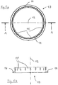
- the clamping ring 13 has an annular contact area 14 and a has cylindrical wall area with the axis 12 as the axis of rotation. This wall area contains a large number of gaps or notches, from which a clamping or "explosive" ring with peripherally arranged crenellated fins 15 results.
- the cuff 1 in the interior of your Bulge area have an annular, bead-like reinforcement.
- This reinforcement is formed in one piece with the cuff 1. It can be circular in cross-section; however, there are others Cross-sectional shapes depending on the respective dimensioning of each Cuff possible.
- springy expansion ring 9 which acts as a support corset in the interior the bulge zone is used. So that becomes a unwanted "denting" of cuff sections effectively avoided.
- FIGS. 4a to 4c show a special embodiment of the Cuff 1 according to the invention shown.
- Can be seen in the peripheral End area of area 6 three lobe-shaped protuberances 10.
- From FIGS. 4a and 4b - and also hinted at from Figure 4c - is a peripheral flattening 11 in the upper region out of 6.
- This flattening 11 is special Embodiment - namely when using these cuffs for a Binocular housing - due to the design, and that because of the small Gap between two eyepiece tubes 2 of a binocular arrangement.
- generous spatial conditions in the binocular swivel range Cuff 1 can also be completely rotationally symmetrical, the axis 12 of the sleeve 1 serving as the "axis of rotation”.
Landscapes
- Physics & Mathematics (AREA)
- General Physics & Mathematics (AREA)
- Optics & Photonics (AREA)
- Chemical & Material Sciences (AREA)
- Analytical Chemistry (AREA)
- Microscoopes, Condenser (AREA)
- Telescopes (AREA)
- Instruments For Viewing The Inside Of Hollow Bodies (AREA)
Abstract
Description
- Figur 1:
- eine Seitenansicht eines Monokular- bzw. Binokular-Mikroskopgehäuses;
- Figur 2:
- einen Querschnitt eines mit einer erfindungsgemäßen Manschette ausgestatteten beweglichen Okulars in Wirkstellung mit angedeutetem Okulargehäuse;
- Figur 3:
- einen Spreizring;
- Figur 4a:
- eine perspektivische Darstellung einer Ausführungsform der erfindungsgemäßen Manschette;
- Figur 4b:
- eine Seitenansicht des in Figur 4a Dargestellten;
- Figur 4c:
- eine Draufsicht des in Figur 4a Dargestellten.
- Figur 5a:
- eine Draufsicht auf den Klemmring;
- Figur 5b:
- einen Schnitt längs der Linie A-A gemäß Fig. 5a.
- 1
- Manschette
- 2
- Okularrohr
- 3
- Okular-/Binokular-Tubusgehäuse
- 4
- (okularseitiger) Haltering
- 5
- (oberer) okularseitiger Teil von (1)
- 6
- (unterer) gehäuseseitiger Teil von (1)
- 7
- Öffnung in (3)
- 8
- umlaufende Nut an der Außenwandung von (2)
- 9
- federnder Spreizring
- 10
- lappenförmige Ausstülpungen im unteren Bereich von (6)
- 11
- periphere Abflachung im oberen Bereich von (6)
- 12
- Achse von (1) bzw. (2)
- 13
- (gehäuseseitiger) Klemmring
- 14
- (ringförmiger) Anlagebereich von (13)
- 15
- (zinnenförmige) Lamellen
Claims (18)
- Manschette für beweglich gehalterte Okularrohre für optische Geräte - insbesondere Binokular-Mikroskope, dadurch gekennzeichnet, dass die Manschette (1) mit ihrem okularseitigen Teil (5) die Außenwand des Okularrohres (2) und mit ihrem gehäuseseitigen Teil (6) die Innenwandung der für das Okularrohr (2) vorgesehenen Öffnung (7) des Tubusgehäuses (3) umgreift.
- Manschette nach Anspruch 1, dadurch gekennzeichnet, dass jeder der beiden Endbereiche (5 bzw. 6) mindestens zwei Kontaktflächen aufweist, die nicht in einer einzigen, senkrecht zur Achse (12) des Okularrohres (2) aufgespannten Ebene liegen.
- Manschette nach Anspruch 1 oder 2, dadurch gekennzeichnet, dass ihr okularseitiger Teil (5) im Querschnitt "L"-förmig ausgebildet ist und in eine in der Außenwand des Okularrohres (2) vorgesehenen Nut (8) eingreift.
- Manschette nach Anspruch 3, dadurch gekennzeichnet, dass der Winkel des im Querschnitt "L"-förmigen Teils (5) kleiner als 90 Grad ist.
- Manschette nach Anspruch 1 oder 2, dadurch gekennzeichnet, dass ihr gehäuseseitiger Teil (6) im Querschnitt die Form eines abgewinkelten "C" aufweist und an der Öffnung (7) im Tubusgehäuse (3) anliegt.
- Manschette nach Anspruch 5, dadurch gekennzeichnet, dass das Tubusgehäuse (3) im Kontaktbereich des Teiles (6) der Manschette (1) im Querschnitt stufenförmig ausgebildet ist.
- Manschette nach mindestens einem der vorhergehenden Ansprüche, dadurch gekennzeichnet, dass sie in ihrem Mittelteil mindestens eine Ausbauchungs-Zone und mindestens eine Taillierungs-Zone aufweist.
- Manschette nach Anspruch 7, dadurch gekennzeichnet, dass die Taillierungs-Zone gehäuseseitig angeordnet ist.
- Manschette nach mindestens einem der vorhergehenden Ansprüche, dadurch gekennzeichnet, dass sie als einteiliger, flexibler Balg ausgeführt ist und aus einem Elastomer besteht.
- Manschette nach Anspruch 9, dadurch gekennzeichnet, dass das Material der Manschette (1) in unterschiedlichen Teilbereichen unterschiedliche Verformungseigenschaften aufweist.
- Manschette nach Anspruch 10, dadurch gekennzeichnet, dass sie in ihren jeweiligen Endbereichen (5 bzw. 6) aus einem Elastomer-Material größerer Härte besteht.
- Manschette nach mindestens einem der vorhergehenden Ansprüche, dadurch gekennzeichnet, dass sie im Innenbereich ihrer Ausbauchungs-Zone eine umlaufende wulstartige Verdickung aufweist.
- Manschette noch mindestens einem der vorhergehenden Ansprüche, dadurch gekennzeichnet, dass ihr gehäuseseitiger Teil (5) in Wirkstellung von einem Haltering (4) umgriffen wird.
- Manschette nach mindestens einem der vorhergehenden Ansprüche, dadurch gekennzeichnet, dass ihr gehäuseseitiger Teil (6) in Wirkstellung durch einen Klemmring (13) ortsfest gehaltert wird.
- Manschette nach mindestens einem der vorhergehenden Ansprüche, dadurch gekennzeichnet, dass sie im unteren Teil ihres zum Gehäuse (3) weisenden Endbereichs (6) mehrere lappenförmige Ausstülpungen (10) aufweist.
- Manschette nach mindestens einem der vorhergehenden Ansprüche, dadurch gekennzeichnet, dass sie aus einem elektrisch leitenden Kunststoff-Material besteht.
- Manschette nach mindestens einem der vorhergehenden Ansprüche, dadurch gekennzeichnet, dass sie in Wirkstellung im Innenbereich ihrer Ausbauchungs-Zone einen einfügbaren, federnden Spreizring (9) aufweist.
- Verwendung von Manschetten nach mindestens einem der vorhergehenden Ansprüche für Okular-Abdichtungen bei antistatischen optischen Geräten, insbesondere Binokular-Mikroskopen.
Applications Claiming Priority (2)
| Application Number | Priority Date | Filing Date | Title |
|---|---|---|---|
| DE10045228A DE10045228C2 (de) | 2000-05-15 | 2000-09-13 | Okularrohr-Manschette |
| DE10045228 | 2000-09-13 |
Publications (2)
| Publication Number | Publication Date |
|---|---|
| EP1189091A2 true EP1189091A2 (de) | 2002-03-20 |
| EP1189091A3 EP1189091A3 (de) | 2004-09-15 |
Family
ID=7656023
Family Applications (1)
| Application Number | Title | Priority Date | Filing Date |
|---|---|---|---|
| EP01114436A Withdrawn EP1189091A3 (de) | 2000-09-13 | 2001-06-15 | Okularrohr-Manschette |
Country Status (1)
| Country | Link |
|---|---|
| EP (1) | EP1189091A3 (de) |
Cited By (2)
| Publication number | Priority date | Publication date | Assignee | Title |
|---|---|---|---|---|
| EP1617266A4 (de) * | 2004-01-28 | 2006-02-15 | Olympus Corp | Mikroskop und messungsdurchführungsverfahren gegen eine statische elektrizitätsentladung bei mikroskopen |
| EP2982948A3 (de) * | 2014-08-08 | 2016-04-13 | Servomex Group Limited | Ausrichtungsvorrichtung und sender/empfänger-mit zwei winkelfreiheitsgraden |
Family Cites Families (6)
| Publication number | Priority date | Publication date | Assignee | Title |
|---|---|---|---|---|
| GB362725A (en) * | 1931-01-13 | 1931-12-10 | Barr & Stroud Ltd | Improvements in optical focussing devices |
| DE1953040U (de) * | 1966-07-23 | 1967-01-05 | Goetzewerke | Abdichtungsvorrichtung, insbesondere fuer kugelgelenke. |
| DE2456564A1 (de) * | 1974-11-29 | 1976-08-12 | Polykarp Voelk | Manschette zum dichten zweier beweglich zueinander angeordneter hohlkoerper |
| AT389919B (de) * | 1986-12-10 | 1990-02-26 | Steyr Daimler Puch Ag | Oeldichtung aus elastisch nachgiebigem werkstoff fuer eine brennkraftmaschine |
| JPH01251019A (ja) * | 1988-03-31 | 1989-10-06 | Minolta Camera Co Ltd | 防水カメラにおける鏡胴部構造 |
| JPH10133086A (ja) * | 1996-10-25 | 1998-05-22 | Nikon Corp | 顕微鏡の接眼レンズ |
-
2001
- 2001-06-15 EP EP01114436A patent/EP1189091A3/de not_active Withdrawn
Cited By (3)
| Publication number | Priority date | Publication date | Assignee | Title |
|---|---|---|---|---|
| EP1617266A4 (de) * | 2004-01-28 | 2006-02-15 | Olympus Corp | Mikroskop und messungsdurchführungsverfahren gegen eine statische elektrizitätsentladung bei mikroskopen |
| EP2982948A3 (de) * | 2014-08-08 | 2016-04-13 | Servomex Group Limited | Ausrichtungsvorrichtung und sender/empfänger-mit zwei winkelfreiheitsgraden |
| US11119290B2 (en) | 2014-08-08 | 2021-09-14 | Servomex Group Limited | Alignment device and transmitter/receiver system with two angular degrees of freedom |
Also Published As
| Publication number | Publication date |
|---|---|
| EP1189091A3 (de) | 2004-09-15 |
Similar Documents
| Publication | Publication Date | Title |
|---|---|---|
| DE2029892A1 (de) | ||
| DE2333760A1 (de) | Kupplung | |
| DE2850946C2 (de) | Verfahren zum Auswechseln des Handschuhs einer Ärmel-Handschuh-Anordnung für Hantierungen in einer abgeschlossenen Kammer und Ärmel-Handschuh-Anordnung hierfür | |
| EP1562064B1 (de) | Umklappbare Augenmuschel | |
| DE3532560A1 (de) | Verschlussvorrichtung fuer das mundstueck eines endoskopes | |
| EP3178438A1 (de) | Schutzadapter für ein operationsmikroskop | |
| DE102017107106A1 (de) | Endoskop mit weitwinkeloptik und arbeitskanal | |
| DE202019102908U1 (de) | Schutzmaske mit einer innenliegenden, schwenkbaren Schutzbrille | |
| DE3341876C2 (de) | ||
| EP4505894A1 (de) | Schutzhelm | |
| DE10045228C2 (de) | Okularrohr-Manschette | |
| DE10339255A1 (de) | Führungssystem für optische Systeme, insbesondere Zoom-Systeme | |
| DE2732326C2 (de) | Clip zum Unterbrechen von Leitungsbahnen | |
| DE4413920B4 (de) | Einsatz für Sichtöffnung eines Drapes und Drape mit solchem Einsatz sowie Operationsmikroskop mit solchem Drape und Einsatz | |
| DE69606757T2 (de) | Vorrichtung mit schützender Wirkung gegen Durchsickern von Flüssigkeiten in elektrischen Schaltern und dergleichen | |
| DE102019122256A1 (de) | Demontage- und Montagewerkzeug für Achsmanschetten | |
| DE102007043995B4 (de) | Drape-Schutzglas-Anordnung für Operations-Mikroskope | |
| EP2281534A1 (de) | Schweisserschutzmaske | |
| EP3384795B1 (de) | Halterung für brillengläser und helm mit solch einer halterung | |
| DE2164752A1 (de) | Differentialdruckschalter | |
| DE4412901A1 (de) | Dioptrieneinstellmechanismus für Ferngläser | |
| DE10311198B4 (de) | Haltevorrichtung mit durchsichtigem Abdeckelement für Drape sowie Drape für ein Operationsmikroskop mit einer solchen Haltevorrichtung | |
| WO2018134669A1 (de) | Endoskop mit einem endoskopkopf und einem am endoskopkopf vorgesehenen hin- und her beweglichen bewegungskörper, und endoskop mit seilzugfeineinstellstruktur | |
| DE2100739C3 (de) | Augenmuschel für ein optisches Gerät | |
| EP0836019A1 (de) | Kugelgelenkförmige Verbindung mit wirksamer Abschirmung gegenüber Einflüssen von aussen |
Legal Events
| Date | Code | Title | Description |
|---|---|---|---|
| PUAI | Public reference made under article 153(3) epc to a published international application that has entered the european phase |
Free format text: ORIGINAL CODE: 0009012 |
|
| AK | Designated contracting states |
Kind code of ref document: A2 Designated state(s): AT BE CH CY DE DK ES FI FR GB GR IE IT LI LU MC NL PT SE TR |
|
| AX | Request for extension of the european patent |
Free format text: AL;LT;LV;MK;RO;SI |
|
| PUAL | Search report despatched |
Free format text: ORIGINAL CODE: 0009013 |
|
| AK | Designated contracting states |
Kind code of ref document: A3 Designated state(s): AT BE CH CY DE DK ES FI FR GB GR IE IT LI LU MC NL PT SE TR |
|
| AX | Request for extension of the european patent |
Extension state: AL LT LV MK RO SI |
|
| RIC1 | Information provided on ipc code assigned before grant |
Ipc: 7G 02B 25/00 B Ipc: 7G 02B 23/16 B Ipc: 7G 02B 7/22 B Ipc: 7G 02B 7/20 B Ipc: 7G 02B 21/24 A |
|
| STAA | Information on the status of an ep patent application or granted ep patent |
Free format text: STATUS: THE APPLICATION HAS BEEN WITHDRAWN |
|
| 17P | Request for examination filed |
Effective date: 20050314 |
|
| 17Q | First examination report despatched |
Effective date: 20050415 |
|
| AKX | Designation fees paid |
Designated state(s): AT BE CH CY DE DK ES FI FR GB GR IE IT LI LU MC NL PT SE TR |
|
| 18W | Application withdrawn |
Effective date: 20050418 |