EP1187352A2 - Montierungsstruktur eines nachrichtenvorrichtungs - Google Patents
Montierungsstruktur eines nachrichtenvorrichtungs Download PDFInfo
- Publication number
- EP1187352A2 EP1187352A2 EP01115191A EP01115191A EP1187352A2 EP 1187352 A2 EP1187352 A2 EP 1187352A2 EP 01115191 A EP01115191 A EP 01115191A EP 01115191 A EP01115191 A EP 01115191A EP 1187352 A2 EP1187352 A2 EP 1187352A2
- Authority
- EP
- European Patent Office
- Prior art keywords
- main body
- communication equipment
- body portion
- fixing portion
- mount structure
- Prior art date
- Legal status (The legal status is an assumption and is not a legal conclusion. Google has not performed a legal analysis and makes no representation as to the accuracy of the status listed.)
- Ceased
Links
Images


Classifications
-
- H—ELECTRICITY
- H05—ELECTRIC TECHNIQUES NOT OTHERWISE PROVIDED FOR
- H05K—PRINTED CIRCUITS; CASINGS OR CONSTRUCTIONAL DETAILS OF ELECTRIC APPARATUS; MANUFACTURE OF ASSEMBLAGES OF ELECTRICAL COMPONENTS
- H05K7/00—Constructional details common to different types of electric apparatus
- H05K7/20—Modifications to facilitate cooling, ventilating, or heating
- H05K7/20009—Modifications to facilitate cooling, ventilating, or heating using a gaseous coolant in electronic enclosures
- H05K7/20127—Natural convection
-
- H—ELECTRICITY
- H04—ELECTRIC COMMUNICATION TECHNIQUE
- H04B—TRANSMISSION
- H04B1/00—Details of transmission systems, not covered by a single one of groups H04B3/00 - H04B13/00; Details of transmission systems not characterised by the medium used for transmission
- H04B1/02—Transmitters
- H04B1/03—Constructional details, e.g. casings, housings
- H04B1/036—Cooling arrangements
Definitions
- the present invention relates to the mount structure of communication equipment and particularly, to the mount structure of communication equipment which can enhance the workability of a setup work.
- the internal heat generation in the communication equipment has increased more and more, and also the outer shape and weight of the overall housing of the communication equipment has also become larger.
- the housing structure of conventional communication equipment is designed as being constructed by an integral type communication equipment 50, and the outer shape and weight of the housing of the communication equipment increase in proportion to the internal power consumption.
- the weight of the communication equipment which a worker can carry by himself/herself is estimated to be equal to about 15 kg (kilogram) at maximum.
- An object of the present invention is to provide the mount structure of communication equipment which can enhance the workability of a setup work and is adapted to the heating value of the main body of the communication equipment and the environmental temperature around the setup place.
- a mount structure of the communication equipment comprises a main body portion containing a communication circuit unit and a fixing portion containing a heat exchanger, wherein the main body portion is fixed on the fixing portion, and the main body portion and the fixing portion are designed to be separable from each other.
- the fixing portion is designed to have a substantially L-shape when it is viewed from the side of the fixing portion and so as to serve as a stand on which the main body portion is supported.
- the stand has a projecting portion which can be fitted to a recess portion formed at the bottom portion of the main body portion.
- the main body portion is equipped with packing means for waterproof on the engagement surface with the fixing portion.
- the fixing portion takes in cold air from the outside by the heat exchanger installed therein, and blows the cold air to the main body portion to exchange the cold air with heat generated by the communication circuit, thereby cooling the main body portion.
- the heat exchange efficiency (dissipation efficiency) of the heat exchanger is selected in conformity with the calorific value of the main body portion and the surrounding environmental temperature condition of a setup place.
- the unitary mass of the communication equipment is reduced and thus the handling of the communication equipment is easy, so that the workability can be enhanced.
- the heat exchange efficiency of the heat exchanger can be adjusted in conformity with the calorific value of the main body of the communication equipment, and thus the optimum heat exchange efficiency can be selected in conformity with the surrounding environmental temperature condition of the setup place.
- the fixing portion has a pedestal portion for supporting the main body of the communication equipment, a fabricating work is easily performed, and when the main body of the communication equipment is out of working order or repaired, it is sufficient to exchange only the main body portion of the communication equipment without detaching the overall equipment from a pole or the like. Therefore, the workability can be enhanced.
- Fig. 2 is a perspective view showing the outlook of communication equipment
- Fig. 3A is an exploded perspective view showing a fabrication state of an embodiment
- Fig. 3B is an perspective view taken in the direction of the arrow "A" " of Fig. 3A
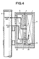
- Fig. 4 is a longitudinally-sectional view showing a use state of the set-up communication equipment.
- the communication equipment comprises two housings of main body portion 1 and fixing portion 2.
- the fixing portion 2 is designed as a housing having a substantially L-shaped section when it is viewed from the side thereof, and serves as a stand on which the main body portion 1 is mounted.
- Heat exchanger 20 of a heat pipe type or the like is accommodated in the fixing portion 2.
- the main body portion 1 of the communication equipment is designed as a box-shaped housing, and communication circuit unit 10 containing a communication circuit is accommodated in the housing.
- Both the housings are integrally assembled with each other so as to form a circulating system in which heat (warm air) generated in the main body of the communication equipment is transferred (sucked) to the fixing portion side and then radiated (cooled) through the heat exchanger 20.
- Recess portion 13 is formed at the bottom surface portion of the main body portion 1 of the communication equipment, and projecting portion 23 which is engageable with the recess portion 13 is formed at the L-shaped pedestal portion of the fixing portion 2.
- the main body portion 1 is fixed on the fixing portion 2 by fixing screws 6.
- the communication equipment comprising the main body portion 1 and the fixing portion 2 is generally fixed to pole 3 or a steel tower.
- the fixing portion 2 is fixed to the pole 3 by a band or the like.
- the main body portion 1 is designed so as to be mounted on the L-shaped pedestal at the lower portion of the fixing portion 2.
- the main body 1 of the communication equipment can be naturally set up at a predetermined position when the recess portion 13 of the main body 1 is fitted to the projecting portion 23 of the pedestal.
- Waterproof packing 5 is mounted on the back surface of the main body 1 of the communication equipment, and thus it acts to hermetically seal both the housings of the main body portion 1 and the fixing portion 2 after they are assembled.
- the heat exchanger 20 is mounted in the fixing portion 2 to form a circulating system in which heat (warm air) at the main body portion 1 is sucked and radiated to the outside, and the outside air (cold air) is blown into the main body portion 1.
- the main body portion 1 has air-intake hole 11 and air-exhaust hole 12 on the face of the fixing side.
- the fixing portion 2 has air-intake hole 21 and air-exhaust hole 22 on the face of the fixing side.
- the air-intake hole 11 and the air-exhaust hole 22 are fitted so as to pass cold air.
- the air-exhaust hole 12 and the air-intake hole 21 are fitted so as to pass warm air.
- the specification of the heat exchanger 20 is determined in accordance with the using environmental temperature of the heat exchanger 20 and the power consumption of the main body portion 1. As is apparent from the figures, even when the main body 1 is out of working order, it is unnecessary to detach the overall equipment (both the fixing portion and the main body portion) from the pole unlike the conventional communication equipment as shown in Fig. 1, and thus the communication equipment can be relatively easily exchanged.
- the fixing portion 2 is structured as an L-shaped pedestal.
- the fixing portion 2 is designed in an inverted L-shape as shown in Fig. 5.
- a hook(s) or the like is provided to the portion corresponding to a roof so as to easily suspend the main body portion 1 of the communication equipment, and the main body portion 1 is fixed to the fixing portion 2 by fixing screws 6. Therefore, the portion corresponding to the roof is designed in a drip-proof structure.
- the other structures and functions are the same as the above embodiment.
- the weight of the communication equipment is preferably set so that a worker can carry out the communication equipment by himself/herself.
- the fixing portion is first fixed to a pole and then the main body of the communication equipment is assembled. Therefore, the workability can be enhanced.
- the main body of the communication equipment when the main body of the communication equipment is subjected to maintenance, it is sufficient to exchange only the main body portion having a relatively higher failure risk, and the it can be more easily detached from the pole. That is, by setting the weight of each of the fixing portion and the main body of the communication equipment to (for example) about 15 kg, the worker can easily perform the assembling or detaching work by himself/herself.
- the heat exchanger is mounted in the fixing portion, and the adjustment of the cooling capability can be performed in accordance with the setup environment.
Landscapes
- Engineering & Computer Science (AREA)
- Microelectronics & Electronic Packaging (AREA)
- Physics & Mathematics (AREA)
- Thermal Sciences (AREA)
- Computer Networks & Wireless Communication (AREA)
- Signal Processing (AREA)
- Casings For Electric Apparatus (AREA)
- Cooling Or The Like Of Electrical Apparatus (AREA)
- Transmitters (AREA)
Applications Claiming Priority (2)
| Application Number | Priority Date | Filing Date | Title |
|---|---|---|---|
| JP2000188165A JP3661766B2 (ja) | 2000-06-22 | 2000-06-22 | 通信機器の実装構造 |
| JP2000188165 | 2000-06-22 |
Publications (2)
| Publication Number | Publication Date |
|---|---|
| EP1187352A2 true EP1187352A2 (de) | 2002-03-13 |
| EP1187352A3 EP1187352A3 (de) | 2004-03-10 |
Family
ID=18688005
Family Applications (1)
| Application Number | Title | Priority Date | Filing Date |
|---|---|---|---|
| EP01115191A Ceased EP1187352A3 (de) | 2000-06-22 | 2001-06-22 | Montierungsstruktur eines nachrichtenvorrichtungs |
Country Status (3)
| Country | Link |
|---|---|
| US (1) | US6427762B2 (de) |
| EP (1) | EP1187352A3 (de) |
| JP (1) | JP3661766B2 (de) |
Cited By (1)
| Publication number | Priority date | Publication date | Assignee | Title |
|---|---|---|---|---|
| CN108934152A (zh) * | 2018-07-28 | 2018-12-04 | 西安交通大学 | 一种自然对流散热的换热强化装置及其设计方法 |
Families Citing this family (9)
| Publication number | Priority date | Publication date | Assignee | Title |
|---|---|---|---|---|
| WO2004006640A1 (ja) | 2002-07-09 | 2004-01-15 | Fujitsu Limited | 熱交換器 |
| EP1843476B1 (de) * | 2006-04-05 | 2014-01-08 | E-Blink | Mast-montierte Antenne mit ausserhalb eines Übertragungsgehäuses angeordnetem Verstärker |
| JP5041365B2 (ja) * | 2007-11-28 | 2012-10-03 | 日本電気株式会社 | 屋外通信装置の設置構造及び設置方法 |
| EP2113963A1 (de) * | 2008-05-02 | 2009-11-04 | Nokia Siemens Networks Oy | Gehäuse- und Montageanordnung für eine Antenne |
| DE102008053220A1 (de) * | 2008-10-25 | 2009-12-31 | Eads Deutschland Gmbh | Anordnung für eine Mastanlage |
| ES2366999T3 (es) * | 2009-09-11 | 2011-10-27 | Calpeda S.P.A. | Contenedor para equipo eléctrico y/o electrónico provisto de mecanismos de disipación del calor y conversor de frecuencia encastrado en dicho conversor. |
| TW201218912A (en) * | 2010-10-20 | 2012-05-01 | Delta Electronics Inc | Waterproof module and cabinet employing the same |
| US20150099448A1 (en) * | 2013-10-08 | 2015-04-09 | Ge Oil & Gas Esp, Inc. | Vent box |
| DE102014108396A1 (de) * | 2014-06-13 | 2015-12-17 | Ebm-Papst St. Georgen Gmbh & Co. Kg | Antennenanordnung mit einer Lüftereinheit |
Family Cites Families (10)
| Publication number | Priority date | Publication date | Assignee | Title |
|---|---|---|---|---|
| US3396780A (en) * | 1966-06-23 | 1968-08-13 | Udylite Corp | Add-on cooling system |
| DE3045326C2 (de) * | 1980-12-02 | 1982-10-21 | Autz & Hermann, 6900 Heidelberg | Zur staubfreien Kühlung eines Schaltschrankes dienender Wärmetauscher |
| US4535386A (en) * | 1983-05-23 | 1985-08-13 | Allen-Bradley Company | Natural convection cooling system for electronic components |
| GB8315893D0 (en) | 1983-06-09 | 1983-07-13 | Overseas Promotions Ltd | Disc camera drive |
| US5040095A (en) * | 1990-05-03 | 1991-08-13 | Alcatel Na Network Systems Corp. | Thermally controlled equipment cabinet |
| US5467250A (en) * | 1994-03-21 | 1995-11-14 | Hubbell Incorporated | Electrical cabinet with door-mounted heat exchanger |
| FI956361A7 (fi) * | 1995-12-29 | 1997-06-30 | Nokia Corp | Jäähdytysjärjestely ja menetelmä laitekotelon jäähdyttämiseksi |
| JP3024610B2 (ja) | 1997-10-13 | 2000-03-21 | 日本電気株式会社 | 密閉型通信機器 |
| JP3033735B2 (ja) * | 1998-06-17 | 2000-04-17 | 日本電気株式会社 | 密閉型筐体 |
| US6164369A (en) * | 1999-07-13 | 2000-12-26 | Lucent Technologies Inc. | Door mounted heat exchanger for outdoor equipment enclosure |
-
2000
- 2000-06-22 JP JP2000188165A patent/JP3661766B2/ja not_active Expired - Fee Related
-
2001
- 2001-06-21 US US09/884,923 patent/US6427762B2/en not_active Expired - Fee Related
- 2001-06-22 EP EP01115191A patent/EP1187352A3/de not_active Ceased
Cited By (1)
| Publication number | Priority date | Publication date | Assignee | Title |
|---|---|---|---|---|
| CN108934152A (zh) * | 2018-07-28 | 2018-12-04 | 西安交通大学 | 一种自然对流散热的换热强化装置及其设计方法 |
Also Published As
| Publication number | Publication date |
|---|---|
| JP3661766B2 (ja) | 2005-06-22 |
| EP1187352A3 (de) | 2004-03-10 |
| JP2002009455A (ja) | 2002-01-11 |
| US20010054494A1 (en) | 2001-12-27 |
| US6427762B2 (en) | 2002-08-06 |
Similar Documents
| Publication | Publication Date | Title |
|---|---|---|
| US6427762B2 (en) | Mount structure of communication equipment | |
| WO2004105261A1 (en) | Housing apparatus for outdoor communication device | |
| CA2367099A1 (en) | Method for operating a fuel cell facility, and fuel cell facility | |
| JP2006156465A (ja) | 放熱部材および該放熱部材を有する屋外用通信機器 | |
| JP2016021278A (ja) | 背負式電源 | |
| KR100664585B1 (ko) | 중계기용 함체 | |
| CN208489681U (zh) | 一种带有散热功能的无线充电底座 | |
| CN215733564U (zh) | 一种无线充电装置 | |
| WO2014077386A1 (ja) | 背負式電源 | |
| CN210725865U (zh) | 一种具有降温节电功能的通信工程箱 | |
| US20090036167A1 (en) | System and method for base station heat dissipation using chimneys | |
| KR100801677B1 (ko) | 통신 중계기의 냉각 장치 | |
| CN219420062U (zh) | 无源式配电箱的散热机构 | |
| CN213214233U (zh) | 一种弱电智能化系统用散热电控箱 | |
| CN217477040U (zh) | 车载主机及具有其的车辆 | |
| JP2004006744A (ja) | 電子機器用冷却装置 | |
| CN209142408U (zh) | 一种具有外置散热器的轻量化无人机云台 | |
| CN222048128U (zh) | 一种箱式顶出风机组 | |
| CN219107578U (zh) | 一种地铁车站通信装置 | |
| JP4192340B2 (ja) | 設備用冷却装置 | |
| CN218085394U (zh) | 车载主机及具有其的车辆 | |
| CN219124203U (zh) | 一种自动组网对讲机 | |
| CN218257651U (zh) | 一种自带发电系统的车载制冷器 | |
| CN222953747U (zh) | 一种无线充电器 | |
| CN113985683B (zh) | 一种影视灯系统 |
Legal Events
| Date | Code | Title | Description |
|---|---|---|---|
| PUAI | Public reference made under article 153(3) epc to a published international application that has entered the european phase |
Free format text: ORIGINAL CODE: 0009012 |
|
| AK | Designated contracting states |
Kind code of ref document: A2 Designated state(s): AT BE CH CY DE DK ES FI FR GB GR IE IT LI LU MC NL PT SE TR |
|
| AX | Request for extension of the european patent |
Free format text: AL;LT;LV;MK;RO;SI |
|
| RIN1 | Information on inventor provided before grant (corrected) |
Inventor name: OYAMADA, TAKASHI |
|
| PUAL | Search report despatched |
Free format text: ORIGINAL CODE: 0009013 |
|
| RIC1 | Information provided on ipc code assigned before grant |
Ipc: 7H 05K 7/20 B Ipc: 7H 04B 1/036 B Ipc: 7H 04B 1/38 A |
|
| AK | Designated contracting states |
Kind code of ref document: A3 Designated state(s): AT BE CH CY DE DK ES FI FR GB GR IE IT LI LU MC NL PT SE TR |
|
| AX | Request for extension of the european patent |
Extension state: AL LT LV MK RO SI |
|
| 17P | Request for examination filed |
Effective date: 20040902 |
|
| AKX | Designation fees paid |
Designated state(s): DE GB SE |
|
| 17Q | First examination report despatched |
Effective date: 20041117 |
|
| STAA | Information on the status of an ep patent application or granted ep patent |
Free format text: STATUS: THE APPLICATION HAS BEEN REFUSED |
|
| 18R | Application refused |
Effective date: 20060624 |