EP1186840B1 - Verfahren und Vorrichtung zur Überwachung des Füllungszustandes einer Kraftfahrzeugklimaanlage - Google Patents
Verfahren und Vorrichtung zur Überwachung des Füllungszustandes einer Kraftfahrzeugklimaanlage Download PDFInfo
- Publication number
- EP1186840B1 EP1186840B1 EP01121430A EP01121430A EP1186840B1 EP 1186840 B1 EP1186840 B1 EP 1186840B1 EP 01121430 A EP01121430 A EP 01121430A EP 01121430 A EP01121430 A EP 01121430A EP 1186840 B1 EP1186840 B1 EP 1186840B1
- Authority
- EP
- European Patent Office
- Prior art keywords
- compressor
- fluid pressure
- expansion device
- downstream
- reached
- Prior art date
- Legal status (The legal status is an assumption and is not a legal conclusion. Google has not performed a legal analysis and makes no representation as to the accuracy of the status listed.)
- Expired - Lifetime
Links
Images

Classifications
-
- B—PERFORMING OPERATIONS; TRANSPORTING
- B60—VEHICLES IN GENERAL
- B60H—ARRANGEMENTS OF HEATING, COOLING, VENTILATING OR OTHER AIR-TREATING DEVICES SPECIALLY ADAPTED FOR PASSENGER OR GOODS SPACES OF VEHICLES
- B60H1/00—Heating, cooling or ventilating [HVAC] devices
- B60H1/32—Cooling devices
- B60H1/3204—Cooling devices using compression
- B60H1/3225—Cooling devices using compression characterised by safety arrangements, e.g. compressor anti-seizure means or by signalling devices
-
- B—PERFORMING OPERATIONS; TRANSPORTING
- B60—VEHICLES IN GENERAL
- B60H—ARRANGEMENTS OF HEATING, COOLING, VENTILATING OR OTHER AIR-TREATING DEVICES SPECIALLY ADAPTED FOR PASSENGER OR GOODS SPACES OF VEHICLES
- B60H1/00—Heating, cooling or ventilating [HVAC] devices
- B60H1/00642—Control systems or circuits; Control members or indication devices for heating, cooling or ventilating devices
- B60H1/00978—Control systems or circuits characterised by failure of detection or safety means; Diagnostic methods
-
- F—MECHANICAL ENGINEERING; LIGHTING; HEATING; WEAPONS; BLASTING
- F25—REFRIGERATION OR COOLING; COMBINED HEATING AND REFRIGERATION SYSTEMS; HEAT PUMP SYSTEMS; MANUFACTURE OR STORAGE OF ICE; LIQUEFACTION SOLIDIFICATION OF GASES
- F25B—REFRIGERATION MACHINES, PLANTS OR SYSTEMS; COMBINED HEATING AND REFRIGERATION SYSTEMS; HEAT PUMP SYSTEMS
- F25B49/00—Arrangement or mounting of control or safety devices
- F25B49/005—Arrangement or mounting of control or safety devices of safety devices
-
- F—MECHANICAL ENGINEERING; LIGHTING; HEATING; WEAPONS; BLASTING
- F25—REFRIGERATION OR COOLING; COMBINED HEATING AND REFRIGERATION SYSTEMS; HEAT PUMP SYSTEMS; MANUFACTURE OR STORAGE OF ICE; LIQUEFACTION SOLIDIFICATION OF GASES
- F25B—REFRIGERATION MACHINES, PLANTS OR SYSTEMS; COMBINED HEATING AND REFRIGERATION SYSTEMS; HEAT PUMP SYSTEMS
- F25B2500/00—Problems to be solved
- F25B2500/22—Preventing, detecting or repairing leaks of refrigeration fluids
- F25B2500/222—Detecting refrigerant leaks
-
- F—MECHANICAL ENGINEERING; LIGHTING; HEATING; WEAPONS; BLASTING
- F25—REFRIGERATION OR COOLING; COMBINED HEATING AND REFRIGERATION SYSTEMS; HEAT PUMP SYSTEMS; MANUFACTURE OR STORAGE OF ICE; LIQUEFACTION SOLIDIFICATION OF GASES
- F25B—REFRIGERATION MACHINES, PLANTS OR SYSTEMS; COMBINED HEATING AND REFRIGERATION SYSTEMS; HEAT PUMP SYSTEMS
- F25B2700/00—Sensing or detecting of parameters; Sensors therefor
- F25B2700/04—Refrigerant level
-
- F—MECHANICAL ENGINEERING; LIGHTING; HEATING; WEAPONS; BLASTING
- F25—REFRIGERATION OR COOLING; COMBINED HEATING AND REFRIGERATION SYSTEMS; HEAT PUMP SYSTEMS; MANUFACTURE OR STORAGE OF ICE; LIQUEFACTION SOLIDIFICATION OF GASES
- F25B—REFRIGERATION MACHINES, PLANTS OR SYSTEMS; COMBINED HEATING AND REFRIGERATION SYSTEMS; HEAT PUMP SYSTEMS
- F25B2700/00—Sensing or detecting of parameters; Sensors therefor
- F25B2700/19—Pressures
- F25B2700/195—Pressures of the condenser
-
- F—MECHANICAL ENGINEERING; LIGHTING; HEATING; WEAPONS; BLASTING
- F25—REFRIGERATION OR COOLING; COMBINED HEATING AND REFRIGERATION SYSTEMS; HEAT PUMP SYSTEMS; MANUFACTURE OR STORAGE OF ICE; LIQUEFACTION SOLIDIFICATION OF GASES
- F25B—REFRIGERATION MACHINES, PLANTS OR SYSTEMS; COMBINED HEATING AND REFRIGERATION SYSTEMS; HEAT PUMP SYSTEMS
- F25B2700/00—Sensing or detecting of parameters; Sensors therefor
- F25B2700/19—Pressures
- F25B2700/197—Pressures of the evaporator
-
- F—MECHANICAL ENGINEERING; LIGHTING; HEATING; WEAPONS; BLASTING
- F25—REFRIGERATION OR COOLING; COMBINED HEATING AND REFRIGERATION SYSTEMS; HEAT PUMP SYSTEMS; MANUFACTURE OR STORAGE OF ICE; LIQUEFACTION SOLIDIFICATION OF GASES
- F25B—REFRIGERATION MACHINES, PLANTS OR SYSTEMS; COMBINED HEATING AND REFRIGERATION SYSTEMS; HEAT PUMP SYSTEMS
- F25B45/00—Arrangements for charging or discharging refrigerant
Definitions
- the present invention relates to a method of monitoring the state of filling of a motor-vehicle air-conditioning system comprising a fluid circuit, including:
- the operation of the compressor of the air-conditioning system is prevented when the pressure of the fluid in the system falls below a predetermined threshold, for example about 3.1 bar, at rest.
- a predetermined threshold for example about 3.1 bar
- a method and apparatus for monitoring the state of filling of an air conditioning system in a motor-vehicle is known from document WO-A-9 416 273.
- the aim of the present invention is therefore to propose a method which enables the state of filling of an air-conditioning system installed in a motor vehicle to be monitored in a reliable, simple, and economical manner.
- the invention also consists of a system for performing the monitoring of the state of filling of a motor-vehicle air-conditioning system, the main characteristics of which are defined in Claim 9.
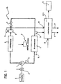
- FIG. 1 the internal combustion engine of a motor vehicle is indicated E and an air-conditioning system installed in the motor vehicle is generally indicated CS.
- the air-conditioning system CS comprises, in a per se known manner, a compressor 1 which can be driven by the internal combustion engine E, by means of an electrically-operated coupling 2.
- the output of the compressor 1 is connected to the input of a condenser 3.
- the output of the condenser is connected to a filter 4 downstream of which there is a fluid-expansion device 5.
- This device may be, for example, an expansion valve, or even simply a calibrated opening.
- the expansion device 5 is connected to the input of an evaporator 6 the output of which is connected to the input of the compressor 1.
- An electric fan 7 is associated with the evaporator 6.
- a monitoring system is associated with the air-conditioning system CS for monitoring its state of filling.
- the monitoring system comprises, basically, an electronic control unit ECU which is arranged to control the operation of the coupling 2 and of the electric fan 7 associated with the evaporator, in accordance with predetermined methods.
- Signals indicative of the rate of rotation of the engine E reach an input 8 of the control unit ECU.
- These signals may be signals which reach the unit ECU from a sensor associated with the engine E, or signals indicative of this rate and coming from the electronic engine-management unit or from a network for the distribution of signals in the motor vehicle, such as a network operating in accordance with the CAN protocol.
- the system for monitoring the state of filling of the air-conditioning system CS also comprises (at least) one electric pressure sensor 9 connected to an input 10 of the control unit ECU.
- This sensor is, for example, an analog sensor.
- the pressure sensor 9 is associated with the high-pressure branch of the refrigeration circuit of the air-conditioning system and is thus located upstream of the expansion device 5, typically downstream of the condenser 3, and is, for example, associated with the filter 4.
- control unit ECU In order to monitor the state of filling of the system, the control unit ECU is arranged to bring about, every so often, for example, each time the engine E is switched on and started, activation of the compressor 1 for a predetermined period of time (for example, 10 seconds) whilst the engine E is rotating at a substantially constant rate (for example, at idling speed) and whilst the fan 7 associated with the evaporator 6 is kept deactivated. After this period of time, the unit ECU brings about deactivation of the compressor 1 (by means of the coupling 2).
- a predetermined period of time for example, 10 seconds
- the unit ECU brings about deactivation of the compressor 1 (by means of the coupling 2).
- the unit ECU detects the behaviour of the fluid pressure indicated by the sensor 9.
- the curve of the signal provided by this sensor is, for example that indicated P H in Figure 2.
- the signal P H adopts a rest value P H0 prior to the activation of the compressor 1, which is brought about by the unit ECU at a moment t 1 .
- the unit ECU brings about deactivation of the compressor 1 and the pressure indicated by the sensor 9 starts to decrease, starting from the maximum value P Hmax reached at the moment t 2 , and tending to return progressively to the rest value P H0 .
- the curve indicated P L in Figure 2 is that of the voltage output by the sensor 9 which is indicative of the pressure of the fluid in the hydraulic circuit if the sensor is associated with the low-pressure branch of the refrigeration circuit, and hence if the sensor is located downstream of the expansion device 5, for example, in one of the three positions shown in broken outline in Figure 1, that is, at the input or at the output of the evaporator 6 or in the vicinity of the input of the compressor 1.
- the unit ECU is therefore advantageously arranged to compare the value adopted by one or more of the above-mentioned parameters with reference values predetermined experimentally for the specific system, and to activate an indicator device 11 (Figure 1) when this comparison is indicative of an insufficient level of filling of the system.
- the indicator device 11 may alternatively be activated after a predetermined number of consecutive indications of an insufficient filling level.
- the electric fan 7 associated with the evaporator is kept deactivated.
- the control unit ECU could be arranged to control the electric fan 7 during the period of time T in a manner such that it conveys a predetermined, substantially constant air-flow onto the evaporator.
Landscapes
- Engineering & Computer Science (AREA)
- Physics & Mathematics (AREA)
- Thermal Sciences (AREA)
- Mechanical Engineering (AREA)
- General Engineering & Computer Science (AREA)
- Air-Conditioning For Vehicles (AREA)
- Air Conditioning Control Device (AREA)
Claims (16)
- Verfahren zum Überwachen des Füllzustands einer Klimaanlage (CS) für ein Kraftfahrzeug, wobei die Anlage (CS) einen Fluidkreislauf umfasst, einschließlich:wobei das Verfahren dadurch gekennzeichnet ist, dass:eines Kompressors (1), der am Verbrennungsmotor (E) des Kraftfahrzeugs angeschlossen sein kann und dessen Ausgang an einem Kondensator (3) angeschlossen ist, undeines Verdampfers (6), dem ein Gebläse (7) zugeordnet ist und der mit seinem Eingang mittels einer Fluidexpansionsvorrichtung (5) am Ausgang des Kondensators (3) und mit seinem Ausgang am Eingang des Kompressors angeschlossen ist,der Kompressor (1) für eine vorbestimmte Zeitdauer (T) aktiviert wird, während der Motor (E) des Kraftfahrzeugs mit einer vorbestimmten, im Wesentlichen konstanten Geschwindigkeit rotiert und während das zum Verdampfer (6) gehörige Gebläse (7) solcherart gesteuert wird, dass es dem Verdampfer (6) einen im Wesentlichen konstanten oder auch bei Null liegenden Luftstrom zufnhrt, und der Kompressor (1) danach deaktiviert wird,der Wert von zumindest einer vorbestimmten Eigenschaft der resultierenden Kurve des Fluiddrucks stromaufwärts (PH) und/oder stromabwärts (PL) von der Expansionsvorrichtung (5) mit der Zeit ermittelt wird, unddiese Eigenschaft mit einem vorbestimmten Bezugswert verglichen wird.
- Verfahren gemäß Anspruch 1, wobei die vorbestimmte Eigenschaft jener Höchstoder Mindestwert (PHmax, PLmin) ist, der vom Fluiddruck stromaufwärts bzw. stromabwärts von der Expansionsvorrichtung (5) erreicht wird.
- Verfahren gemäß Anspruch 1, wobei die vorbestimmte Eigenschaft eine Funktion von oder das Verhältnis zwischen dem vom Fluiddruck stromaufwärts bzw. stromabwärts von der Expansionsvorrichtung (5) erreichten Höchst- oder Mindestwert (PHmax, PLmin) und dem vor der Aktivierung des Kompressors (1) vom Druck angenommenen Wert (PH0; PL0) ist.
- Verfahren gemäß Anspruch 2 oder Anspruch 3, wobei der vom Fluiddruck (PH) stromabwärts vom Kondensator (3) erreichte Höchstwert (PHmax) ermittelt wird.
- Verfahren gemäß Anspruch 2 oder Anspruch 3 für eine Anlage (CS), bei welcher am Ausgang aus dem Kondensator (3) ein Fluidfilter (4) angeordnet ist und bei welcher der vom Fluiddruck im Filter (4) erreichte Höchstwert (PHmax) ermittelt wird.
- Verfahren gemäß Anspruch 2 oder Anspruch 3, wobei der Mindestwert (PLmin) ermittelt wird, der vom Fluiddruck (PL) in der Nähe des Eingangs oder des Ausgangs des Verdampfers (6) erreicht wird.
- Verfahren gemäß Anspruch 2 oder Anspruch 3, wobei der Mindestwert (PLmin) ermittelt wird, der vom Fluiddruck (PL) in der Nähe des Eingangs des Kompressors erreicht wird.
- Verfahren gemäß Anspruch 1, wobei die vorbestimmte Eigenschaft eine Funktion oder die Entspannungszeit des Fluiddrucks (PH, PL) stromaufwärts oder stromabwärts von der Expansionsvorrichtung (5) nach der Deaktivierung des Kompressors (1) ist.
- System zum Überwachen des Füllzustands einer Klimaanlage (CS) eines Kraftfahrzeugs, welche einen Fluidkreislauf umfasst, und zwar einschließlich:wobei das System dadurch gekennzeichnet ist, dass es Folgendes umfasst:eines Kompressors (1), der am Verbrennungsmotor (E) des Kraftfahrzeugs angeschlossen sein kann und dessen Ausgang an einem Kondensator (3) angeschlossen ist, undeines Verdampfers (6), dem ein Gebläse (7) zugeordnet ist und der mit seinem Eingang mittels einer Fluidexpansionsvorrichtung (5) am Ausgang des Kondensators (3) und mit seinem Ausgang am Eingang des Kompressors (1) angeschlossen ist,eine Steuereinheit (ECU), die eine geregelte Aktivierung des Kompressors (1) bewirken kann, während der Motor (E) des Kraftfahrzeugs mit einer vorbestimmten, im Wesentlichen konstanten Geschwindigkeit rotiert und während das Gebläse (7) solcherart gesteuert wird, dass es dem Verdampfer (6) einen im Wesentlichen konstanten oder auch bei Null liegenden Luftstrom zuführt, und danach die Deaktivierung des Kompressors (1),Sensormittel (9), um der Steuereinheit (ECU) elektrische Signale zuzuführen, welche den Fluiddruck (PH, PL) stromaufwärts und/oder stromabwärts von der Expansionsvorrichtung (5) anzeigen,wobei die Steuereinheit (ECU) dazu eingerichtet ist, zumindest eine Eigenschaft der Kurve des Fluiddrucks stromaufwärts und/oder stromabwärts von der Expansionsvorrichtung (5) mit der Zeit zu ermitteln, welche aus der Aktivierung des Kompressors (1) resultiert, und diese Eigenschaft mit einem vorbestimmten Bezugswert zu vergleichen.
- System gemäß Anspruch 9, bei welchem die vorbestimmte Eigenschaft jener Höchstoder Mindestwert (PHmax, PLmin) ist, der vom Fluiddruck stromaufwärts bzw. stromabwärts von der Expansionsvorrichtung (5) erreicht wird.
- System gemäß Anspruch 9, bei welchem die vorbestimmte Eigenschaft eine Funktion von oder das Verhältnis zwischen dem vom Fluiddruck stromaufwärts bzw. stromabwärts von der Expansionsvorrichtung (5) erreichten Höchst- oder Mindestwert (PHmax, PLmin) und dem vor der Aktivierung des Kompressors (1) vom Druck angenommenen Wert (PH0; PL0) ist.
- System gemäß Anspruch 10 oder Anspruch 11, bei welchem die Sensormittel (9) solcherart eingerichtet sind, um Signale zu liefern, welche den Fluiddruck (PH) stromabwärts vom Kondensator (3) anzeigen.
- System gemäß Anspruch 10 oder Anspruch 11 für eine Anlage, bei welcher am Ausgang des Kondensators (3) ein Fluidfilter (4) angeordnet ist und bei welcher die Sensormittel (9) dem Filter (4) zugeordnet sind.
- System gemäß Anspruch 10 oder Anspruch 11, bei welchem die Steuereinheit (ECU) dazu eingerichtet ist, den Mindestwert zu ermitteln, der vom Fluiddruck in der Nähe des Eingangs oder des Ausgangs des Verdampfers (6) erreicht wird.
- System gemäß Anspruch 10 oder Anspruch 11, bei welchem die Steuereinheit (ECU) dazu eingerichtet ist, den Mindestwert zu ermitteln, der vom Fluiddruck in der Nähe des Eingangs des Kompressors (1) erreicht wird.
- System gemäß Anspruch 9, bei welchem die vorbestimmte Eigenschaft eine Funktion oder die Entspannungszeit des Fluiddrucks (PH, PL) stromaufwärts oder stromabwärts von der Expansionsvorrichtung (5) nach der Deaktivierung des Kompressors (1) ist.
Applications Claiming Priority (2)
| Application Number | Priority Date | Filing Date | Title |
|---|---|---|---|
| ITTO000857 | 2000-09-12 | ||
| IT2000TO000857A IT1320635B1 (it) | 2000-09-12 | 2000-09-12 | Procedimento e sistema per il monitoraggio dello stato di carica di un impianto di climatizzazione di un autoveicolo. |
Publications (2)
| Publication Number | Publication Date |
|---|---|
| EP1186840A1 EP1186840A1 (de) | 2002-03-13 |
| EP1186840B1 true EP1186840B1 (de) | 2004-12-15 |
Family
ID=11458030
Family Applications (1)
| Application Number | Title | Priority Date | Filing Date |
|---|---|---|---|
| EP01121430A Expired - Lifetime EP1186840B1 (de) | 2000-09-12 | 2001-09-07 | Verfahren und Vorrichtung zur Überwachung des Füllungszustandes einer Kraftfahrzeugklimaanlage |
Country Status (4)
| Country | Link |
|---|---|
| EP (1) | EP1186840B1 (de) |
| DE (1) | DE60107782T2 (de) |
| ES (1) | ES2228718T3 (de) |
| IT (1) | IT1320635B1 (de) |
Cited By (1)
| Publication number | Priority date | Publication date | Assignee | Title |
|---|---|---|---|---|
| EP2018985A2 (de) | 2007-07-26 | 2009-01-28 | Ford Global Technologies, LLC | Klimaanlage für ein Kraftfahrzeug sowie Verfahren zu deren Betrieb |
Families Citing this family (4)
| Publication number | Priority date | Publication date | Assignee | Title |
|---|---|---|---|---|
| US7343750B2 (en) * | 2003-12-10 | 2008-03-18 | Carrier Corporation | Diagnosing a loss of refrigerant charge in a refrigerant system |
| DE102007021874B4 (de) * | 2007-05-10 | 2015-12-17 | Bayerische Motoren Werke Aktiengesellschaft | Verfahren zur Kältemittel-Füllmengenüberwachung |
| DE102008050163A1 (de) | 2008-10-01 | 2010-04-08 | Bayerische Motoren Werke Aktiengesellschaft | Verfahren zur Steuerung oder Regelung einer Fahrzeugklimaanlage |
| DE102008050164B4 (de) | 2008-10-01 | 2023-02-09 | Bayerische Motoren Werke Aktiengesellschaft | Verfahren und Klimaanlagensteuergerät zur Kältemittel-Füllmengenüberwachung |
Family Cites Families (11)
| Publication number | Priority date | Publication date | Assignee | Title |
|---|---|---|---|---|
| JPH0755617B2 (ja) | 1984-09-17 | 1995-06-14 | 株式会社ゼクセル | 車両用空気調和装置 |
| JPH0627598B2 (ja) * | 1986-08-13 | 1994-04-13 | 三菱重工業株式会社 | 冷凍装置における圧力センサの故障診断方法 |
| US5009076A (en) | 1990-03-08 | 1991-04-23 | Temperature Engineering Corp. | Refrigerant loss monitor |
| US5044168A (en) * | 1990-08-14 | 1991-09-03 | Wycoff Lyman W | Apparatus and method for low refrigerant detection |
| WO1994016273A1 (en) * | 1992-12-30 | 1994-07-21 | Nira Automotive Ab | Determining the amount of working fluid in a refrigeration or heat pump system |
| US5152152A (en) * | 1992-02-10 | 1992-10-06 | Thermo King Corporation | Method of determining refrigerant charge |
| US5186014A (en) * | 1992-07-13 | 1993-02-16 | General Motors Corporation | Low refrigerant charge detection system for a heat pump |
| US5457965A (en) | 1994-04-11 | 1995-10-17 | Ford Motor Company | Low refrigerant charge detection system |
| DE19542890C1 (de) * | 1995-11-17 | 1997-07-17 | Hansaconsult Ingenieurgesellsc | Verfahren zur Erkennung von Leckagen in Rohrleitungen |
| DE69914446T2 (de) * | 1998-11-23 | 2004-07-01 | Delphi Technologies, Inc., Troy | Verfahren zur Diagnose einer Klimaanlage |
| US6098412A (en) * | 1999-01-19 | 2000-08-08 | Carrier Corporation | Method for automated detection of leaks in a discharge check valve |
-
2000
- 2000-09-12 IT IT2000TO000857A patent/IT1320635B1/it active
-
2001
- 2001-09-07 DE DE60107782T patent/DE60107782T2/de not_active Expired - Lifetime
- 2001-09-07 ES ES01121430T patent/ES2228718T3/es not_active Expired - Lifetime
- 2001-09-07 EP EP01121430A patent/EP1186840B1/de not_active Expired - Lifetime
Cited By (2)
| Publication number | Priority date | Publication date | Assignee | Title |
|---|---|---|---|---|
| EP2018985A2 (de) | 2007-07-26 | 2009-01-28 | Ford Global Technologies, LLC | Klimaanlage für ein Kraftfahrzeug sowie Verfahren zu deren Betrieb |
| EP2018985A3 (de) * | 2007-07-26 | 2010-05-19 | Ford Global Technologies, LLC | Klimaanlage für ein Kraftfahrzeug sowie Verfahren zu deren Betrieb |
Also Published As
| Publication number | Publication date |
|---|---|
| ITTO20000857A0 (it) | 2000-09-12 |
| EP1186840A1 (de) | 2002-03-13 |
| DE60107782D1 (de) | 2005-01-20 |
| DE60107782T2 (de) | 2005-06-09 |
| ES2228718T3 (es) | 2005-04-16 |
| IT1320635B1 (it) | 2003-12-10 |
| ITTO20000857A1 (it) | 2002-03-12 |
Similar Documents
| Publication | Publication Date | Title |
|---|---|---|
| EP1022552B1 (de) | Prüfung zur automatischen Erfassung von Leckagen zwischen der Hochdruck- und Niederdruckseite eines Kühlungssystems | |
| US5457965A (en) | Low refrigerant charge detection system | |
| US8205461B2 (en) | Method and system for detecting low refrigerant charge and air conditioner protection system | |
| US5635633A (en) | Self-diagnosis apparatus using a pressure sensor | |
| WO2005059490A2 (en) | Diagnosing a loss of refrigerant charge in a refrigerant system | |
| US6748753B2 (en) | Air conditioner | |
| US5046924A (en) | Process and circuit arrangement for controlling a consumer driven by an internal combustion engine | |
| JPH04177072A (ja) | 空調装置 | |
| US6626001B2 (en) | Control apparatus for air-conditioner for motor vehicle | |
| US6446505B1 (en) | Method for monitoring the refrigerant filling level in refrigerating system | |
| EP1186840B1 (de) | Verfahren und Vorrichtung zur Überwachung des Füllungszustandes einer Kraftfahrzeugklimaanlage | |
| JPH09170518A (ja) | 高圧燃料噴射装置付き内燃機関における燃料供給系の漏れ識別方法及び装置 | |
| EP1174295B1 (de) | Steuerungsverfahren zur Verhinderung von Kopfdruckspitzen in einer Fahrzeugklimaanlage | |
| US6351956B1 (en) | A/C clutch short engagement control method at engine start without lock-up sensor | |
| KR101796947B1 (ko) | 차량용 에어컨 시스템의 고장 진단방법 | |
| JPH0972620A (ja) | インジェクション式冷凍装置 | |
| JPH08200234A (ja) | 空気調和機 | |
| CN118254539A (zh) | 空调系统及其控制方法、控制装置、存储介质和车辆 | |
| CN118254528A (zh) | 空调系统及其控制方法、控制装置、存储介质和车辆 | |
| JPH11139153A (ja) | 空調用コンプレッサの焼付き防止装置 | |
| EP1116616B1 (de) | Steuerungsverfahren für ein Fahrzeug mit einer Brennkraftmaschine und eine Hilfseinrichtung | |
| KR200294825Y1 (ko) | 경보장치를 가지는 냉동 탑차량용 냉동 시스템 | |
| JP2014046728A (ja) | 車両用エアコンのコンプレッサの故障診断装置及び故障診断方法 | |
| JPH045120A (ja) | 自動車用空気調和装置 | |
| JP3213456B2 (ja) | 冷蔵庫 |
Legal Events
| Date | Code | Title | Description |
|---|---|---|---|
| PUAI | Public reference made under article 153(3) epc to a published international application that has entered the european phase |
Free format text: ORIGINAL CODE: 0009012 |
|
| AK | Designated contracting states |
Kind code of ref document: A1 Designated state(s): DE ES FR GB IT SE Kind code of ref document: A1 Designated state(s): AT BE CH CY DE DK ES FI FR GB GR IE IT LI LU MC NL PT SE TR |
|
| AX | Request for extension of the european patent |
Free format text: AL;LT;LV;MK;RO;SI |
|
| 17P | Request for examination filed |
Effective date: 20020906 |
|
| AKX | Designation fees paid |
Free format text: DE ES FR GB IT SE |
|
| GRAP | Despatch of communication of intention to grant a patent |
Free format text: ORIGINAL CODE: EPIDOSNIGR1 |
|
| GRAS | Grant fee paid |
Free format text: ORIGINAL CODE: EPIDOSNIGR3 |
|
| GRAA | (expected) grant |
Free format text: ORIGINAL CODE: 0009210 |
|
| AK | Designated contracting states |
Kind code of ref document: B1 Designated state(s): DE ES FR GB IT SE |
|
| REG | Reference to a national code |
Ref country code: GB Ref legal event code: FG4D |
|
| REG | Reference to a national code |
Ref country code: SE Ref legal event code: TRGR |
|
| REG | Reference to a national code |
Ref country code: IE Ref legal event code: FG4D |
|
| REF | Corresponds to: |
Ref document number: 60107782 Country of ref document: DE Date of ref document: 20050120 Kind code of ref document: P |
|
| REG | Reference to a national code |
Ref country code: ES Ref legal event code: FG2A Ref document number: 2228718 Country of ref document: ES Kind code of ref document: T3 |
|
| PLBE | No opposition filed within time limit |
Free format text: ORIGINAL CODE: 0009261 |
|
| STAA | Information on the status of an ep patent application or granted ep patent |
Free format text: STATUS: NO OPPOSITION FILED WITHIN TIME LIMIT |
|
| 26N | No opposition filed |
Effective date: 20050916 |
|
| ET | Fr: translation filed | ||
| PGFP | Annual fee paid to national office [announced via postgrant information from national office to epo] |
Ref country code: ES Payment date: 20060802 Year of fee payment: 6 |
|
| PGFP | Annual fee paid to national office [announced via postgrant information from national office to epo] |
Ref country code: GB Payment date: 20060811 Year of fee payment: 6 |
|
| PGFP | Annual fee paid to national office [announced via postgrant information from national office to epo] |
Ref country code: SE Payment date: 20060831 Year of fee payment: 6 |
|
| PG25 | Lapsed in a contracting state [announced via postgrant information from national office to epo] |
Ref country code: SE Free format text: LAPSE BECAUSE OF NON-PAYMENT OF DUE FEES Effective date: 20070908 |
|
| EUG | Se: european patent has lapsed | ||
| GBPC | Gb: european patent ceased through non-payment of renewal fee |
Effective date: 20070907 |
|
| PG25 | Lapsed in a contracting state [announced via postgrant information from national office to epo] |
Ref country code: GB Free format text: LAPSE BECAUSE OF NON-PAYMENT OF DUE FEES Effective date: 20070907 |
|
| REG | Reference to a national code |
Ref country code: ES Ref legal event code: FD2A Effective date: 20070908 |
|
| PG25 | Lapsed in a contracting state [announced via postgrant information from national office to epo] |
Ref country code: ES Free format text: LAPSE BECAUSE OF NON-PAYMENT OF DUE FEES Effective date: 20070908 |
|
| PGFP | Annual fee paid to national office [announced via postgrant information from national office to epo] |
Ref country code: DE Payment date: 20100922 Year of fee payment: 10 |
|
| PGFP | Annual fee paid to national office [announced via postgrant information from national office to epo] |
Ref country code: IT Payment date: 20110916 Year of fee payment: 11 |
|
| PGFP | Annual fee paid to national office [announced via postgrant information from national office to epo] |
Ref country code: FR Payment date: 20111012 Year of fee payment: 11 |
|
| REG | Reference to a national code |
Ref country code: FR Ref legal event code: ST Effective date: 20130531 |
|
| PG25 | Lapsed in a contracting state [announced via postgrant information from national office to epo] |
Ref country code: DE Free format text: LAPSE BECAUSE OF NON-PAYMENT OF DUE FEES Effective date: 20130403 |
|
| PG25 | Lapsed in a contracting state [announced via postgrant information from national office to epo] |
Ref country code: IT Free format text: LAPSE BECAUSE OF NON-PAYMENT OF DUE FEES Effective date: 20120907 Ref country code: FR Free format text: LAPSE BECAUSE OF NON-PAYMENT OF DUE FEES Effective date: 20121001 |
|
| REG | Reference to a national code |
Ref country code: DE Ref legal event code: R119 Ref document number: 60107782 Country of ref document: DE Effective date: 20130403 |