EP1186775A2 - Verfahren zum Prüfen der Dichtheit eines Brennstoffverteilsystems - Google Patents
Verfahren zum Prüfen der Dichtheit eines Brennstoffverteilsystems Download PDFInfo
- Publication number
- EP1186775A2 EP1186775A2 EP01203296A EP01203296A EP1186775A2 EP 1186775 A2 EP1186775 A2 EP 1186775A2 EP 01203296 A EP01203296 A EP 01203296A EP 01203296 A EP01203296 A EP 01203296A EP 1186775 A2 EP1186775 A2 EP 1186775A2
- Authority
- EP
- European Patent Office
- Prior art keywords
- fuel
- pressure
- surge
- engine
- reference value
- Prior art date
- Legal status (The legal status is an assumption and is not a legal conclusion. Google has not performed a legal analysis and makes no representation as to the accuracy of the status listed.)
- Granted
Links
Images

Classifications
-
- F—MECHANICAL ENGINEERING; LIGHTING; HEATING; WEAPONS; BLASTING
- F02—COMBUSTION ENGINES; HOT-GAS OR COMBUSTION-PRODUCT ENGINE PLANTS
- F02M—SUPPLYING COMBUSTION ENGINES IN GENERAL WITH COMBUSTIBLE MIXTURES OR CONSTITUENTS THEREOF
- F02M65/00—Testing fuel-injection apparatus, e.g. testing injection timing ; Cleaning of fuel-injection apparatus
-
- F—MECHANICAL ENGINEERING; LIGHTING; HEATING; WEAPONS; BLASTING
- F02—COMBUSTION ENGINES; HOT-GAS OR COMBUSTION-PRODUCT ENGINE PLANTS
- F02D—CONTROLLING COMBUSTION ENGINES
- F02D41/00—Electrical control of supply of combustible mixture or its constituents
- F02D41/30—Controlling fuel injection
- F02D41/38—Controlling fuel injection of the high pressure type
- F02D41/3809—Common rail control systems
- F02D41/3836—Controlling the fuel pressure
-
- F—MECHANICAL ENGINEERING; LIGHTING; HEATING; WEAPONS; BLASTING
- F02—COMBUSTION ENGINES; HOT-GAS OR COMBUSTION-PRODUCT ENGINE PLANTS
- F02D—CONTROLLING COMBUSTION ENGINES
- F02D41/00—Electrical control of supply of combustible mixture or its constituents
- F02D41/22—Safety or indicating devices for abnormal conditions
- F02D2041/224—Diagnosis of the fuel system
- F02D2041/225—Leakage detection
-
- F—MECHANICAL ENGINEERING; LIGHTING; HEATING; WEAPONS; BLASTING
- F02—COMBUSTION ENGINES; HOT-GAS OR COMBUSTION-PRODUCT ENGINE PLANTS
- F02D—CONTROLLING COMBUSTION ENGINES
- F02D2200/00—Input parameters for engine control
- F02D2200/02—Input parameters for engine control the parameters being related to the engine
- F02D2200/06—Fuel or fuel supply system parameters
- F02D2200/0602—Fuel pressure
-
- F—MECHANICAL ENGINEERING; LIGHTING; HEATING; WEAPONS; BLASTING
- F02—COMBUSTION ENGINES; HOT-GAS OR COMBUSTION-PRODUCT ENGINE PLANTS
- F02D—CONTROLLING COMBUSTION ENGINES
- F02D41/00—Electrical control of supply of combustible mixture or its constituents
- F02D41/02—Circuit arrangements for generating control signals
- F02D41/04—Introducing corrections for particular operating conditions
- F02D41/12—Introducing corrections for particular operating conditions for deceleration
- F02D41/123—Introducing corrections for particular operating conditions for deceleration the fuel injection being cut-off
Definitions
- the present invention is concerned with an engine in which individual injectors connected to a common fuel supply rail are used to inject fuel directly into the combustion chambers of the engine.
- the fuel rail needs to be maintained under high pressure by a fuel pump and the present invention seeks to provide a method and apparatus for detecting fuel leakage from the fuel rail and the pipes connected to it.
- JP-A-10.089.1305 a method for detecting fuel leakage is proposed which compares an expected pressure drop at a given time with a measured pressure drop. In practice, such a method may give rise to inaccurate measurements as it requires a very strict observation of the time-pressure relation.
- a method of detecting leakage in the fuel supply to the injectors of an engine in which the individual injectors are connected to a fuel supply rail to which fuel from a reservoir is supplied under pressure by a fuel pump, the method comprising the steps of monitoring the pressure within the fuel rail and determining when a parameter of a pressure surge in the fuel supply rail resulting from a rapid transition from high to low engine load fails to reach a reference value.
- an apparatus for detecting leakage in the fuel supply to the injectors of an engine in which the individual injectors are connected to a fuel supply rail to which fuel from a reservoir is supplied under pressure by a fuel pump, the apparatus comprising means for measuring the pressure within the fuel rail and means for determining when a parameter of a measured pressure surge in the fuel supply rail resulting from a rapid transition from high to low engine load fails to reach a reference value.
- the surge can be measured on such occasions when the accelerator is released suddenly, preferably when the engine is operating at or near full load, as the surge then will be at its maximum level.
- the peak pressure and decay time of the surge that should occur under these circumstances will depend on the engine speed.
- the algorithm can be made more efficient by allowing the calibration to learn the characteristics of the particular fuel system during the first few hours of operation. As long as the measured values prove to be within an expected range, then they may serve as a baseline from which changes should be measured.
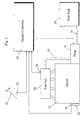
- FIG. 1 shows a diesel engine 10 having a fuel pump 12 that draws fuel from a tank 14 by way of a pipe 16 and supplies fuel under pressure to a fuel rail 20 by way of a pipe 18. From the fuel rail 20, fuel flows to the individual injectors (not shown).
- the pump 12 is controlled by an engine controller 30 which receives inputs from various sensors, amongst them a pressure sensor 24 detecting the pressure in the fuel rail 20, an engine speed/position sensor 32 associated with the crankshaft 22 of the engine 10 and a position sensor 26 sensitive to the position of the accelerator or demand pedal 28.
- the controller may additionally include a clock to enable it to predict wear in the system.
- the curve A shows the pressure variation in the fuel rail when the accelerator pedal is released with the engine running at 2500 rpm while the curve B shows the pressure variation if the release of the accelerator pedal occurs with the engine running at 700 rpm.
- the engine controller 30 which is itself a micro-computer serving several other functions, may be used to store or calculate tables of expected pressure surge magnitude and duration occurring at different speeds (or other engine control parameters affecting the fuel rail pressure surge) and to compare the expected values with actual values sensed by the sensor 24. When the difference between expected and measured surge peaks and/or surge durations drops below a threshold, then the controller 30 can issue a warning of a suspected leak in the fuel rail.
- the values of surge pressure and duration may vary between fuel systems and it is possible to compensate for such variation by adopting a self-learning algorithm in the controller 30.
- the time integral of the pressure during the surge also may be used as the decisive parameter.
Applications Claiming Priority (2)
| Application Number | Priority Date | Filing Date | Title |
|---|---|---|---|
| GB0021923A GB2366598A (en) | 2000-09-07 | 2000-09-07 | Detecting leakage in the fuel rail of an i.c. engine |
| GB0021923 | 2000-09-07 |
Publications (3)
| Publication Number | Publication Date |
|---|---|
| EP1186775A2 true EP1186775A2 (de) | 2002-03-13 |
| EP1186775A3 EP1186775A3 (de) | 2004-01-02 |
| EP1186775B1 EP1186775B1 (de) | 2005-10-26 |
Family
ID=9898998
Family Applications (1)
| Application Number | Title | Priority Date | Filing Date |
|---|---|---|---|
| EP01203296A Expired - Lifetime EP1186775B1 (de) | 2000-09-07 | 2001-08-31 | Verfahren zum Prüfen der Dichtheit eines Brennstoffverteilsystems |
Country Status (6)
| Country | Link |
|---|---|
| US (1) | US20030172720A1 (de) |
| EP (1) | EP1186775B1 (de) |
| JP (1) | JP4750978B2 (de) |
| AT (1) | ATE307973T1 (de) |
| DE (1) | DE60114336T2 (de) |
| GB (1) | GB2366598A (de) |
Cited By (6)
| Publication number | Priority date | Publication date | Assignee | Title |
|---|---|---|---|---|
| DE102004005851A1 (de) * | 2004-02-06 | 2005-09-08 | Audi Ag | Vorrichtung und Verfahren zum Überwachen einer Kraftstofffördervorrichtung |
| FR2919678A1 (fr) * | 2007-08-02 | 2009-02-06 | Renault Sas | Procede et dispositif pour diagnostiquer une fuite d'injecteur dans un moteur a combustion interne |
| DE102008024545A1 (de) * | 2008-05-21 | 2009-11-26 | Continental Automotive Gmbh | Verfahren und Vorrichtung zur Diagnose eines Fehlers, insbesondere in einem Niederdruckbereich eines Kraftstoff-Einspritzsystems eines Verbrennungsmotors |
| DE102011005527A1 (de) | 2011-03-15 | 2012-09-20 | Robert Bosch Gmbh | Verfahren zur Prüfung der Kraftstoffmengenbilanz in einem Common Rail System, entsprechende Motorsteuerung sowie entsprechendes Diagnosegerät |
| CN103868659A (zh) * | 2013-12-31 | 2014-06-18 | 广西玉柴机器股份有限公司 | 一种气缸盖喷油器铜套密封性试漏方法 |
| CN105033637A (zh) * | 2015-08-21 | 2015-11-11 | 广西淞森车用部件有限公司 | 一种燃油分配器总成装配装置及其装配使用方法 |
Families Citing this family (9)
| Publication number | Priority date | Publication date | Assignee | Title |
|---|---|---|---|---|
| DE102004044450B3 (de) * | 2004-09-14 | 2006-04-06 | Siemens Ag | Verfahren und Vorrichtung zur Leerhuberkennung von Injektoren |
| EP1829726A1 (de) * | 2006-03-03 | 2007-09-05 | Inergy Automotive Systems Research (SA) | Verfahren zur Dampfrückgewinnung während des Befüllens |
| IT1398227B1 (it) * | 2009-06-09 | 2013-02-22 | Magneti Marelli Spa | Metodo per l'auto apprendimento della variazione di una caratteristica di funzionamento nominale di una pompa ad alta pressione a portata variabile in un motore a combustione interna |
| JP5163810B2 (ja) * | 2010-10-19 | 2013-03-13 | トヨタ自動車株式会社 | 内燃機関におけるリーク機構診断装置 |
| JP6184756B2 (ja) * | 2013-05-31 | 2017-08-23 | 東日本旅客鉄道株式会社 | 燃料漏れ検知装置 |
| CN104748915A (zh) * | 2013-12-26 | 2015-07-01 | 上海众源燃油分配器制造有限公司 | 一种用于高压燃油管低压检漏的工装 |
| DE102019200978B4 (de) * | 2019-01-25 | 2020-11-12 | Vitesco Technologies GmbH | Verfahren und Vorrichtung zur Überprüfung der Funktionsfähigkeit eines Kurbelgehäuseentlüftungssystems eines Verbrennungsmotors |
| US11286874B2 (en) * | 2019-08-26 | 2022-03-29 | GM Global Technology Operations LLC | Method for fuel injector characterization |
| US11459970B2 (en) | 2021-02-24 | 2022-10-04 | Caterpillar Inc. | Fuel leak detection system |
Citations (1)
| Publication number | Priority date | Publication date | Assignee | Title |
|---|---|---|---|---|
| JPH1089135A (ja) | 1996-09-20 | 1998-04-07 | Toyota Motor Corp | 燃料供給装置 |
Family Cites Families (15)
| Publication number | Priority date | Publication date | Assignee | Title |
|---|---|---|---|---|
| JPH07122422B2 (ja) * | 1986-05-02 | 1995-12-25 | 日本電装株式会社 | 燃料噴射装置 |
| DE3714697A1 (de) * | 1987-05-02 | 1988-11-10 | Vdo Schindling | Einrichtung zur ermittlung und/oder beeinflussung von betriebsdaten von kraftfahrzeugen mit verbrennungsmotor |
| US5133323A (en) * | 1991-06-25 | 1992-07-28 | Siemens Automotive L.P. | Intake manifold pressure compensation for the closed-loop pressure regulation of a fuel pump |
| JP2956302B2 (ja) * | 1991-09-06 | 1999-10-04 | 株式会社デンソー | 内燃機関の異常診断装置 |
| DE19520300A1 (de) * | 1995-06-02 | 1996-12-05 | Bosch Gmbh Robert | Einrichtung zur Erkennung eines Lecks in einem Kraftstoffversorgungssystem |
| JPH0942105A (ja) * | 1995-08-02 | 1997-02-10 | Hino Motors Ltd | 燃料漏れ検出装置 |
| JPH09170512A (ja) * | 1995-12-21 | 1997-06-30 | Nippon Soken Inc | 蓄圧式燃料噴射装置における圧力制御装置 |
| JP3995118B2 (ja) * | 1995-11-09 | 2007-10-24 | ローベルト ボツシユ ゲゼルシヤフト ミツト ベシユレンクテル ハフツング | 高圧燃料噴射装置付き内燃機関における燃料供給系の漏れ識別方法及び装置 |
| ES2174137T3 (es) * | 1996-01-19 | 2002-11-01 | Fiat Ricerche | Metodo y unidad de diagnostico de fugas de un sistema de inyeccion de alta presion de un motor de combustion interna. |
| JP3750754B2 (ja) * | 1996-05-14 | 2006-03-01 | 株式会社デンソー | 内燃機関用燃料供給装置 |
| US5685268A (en) * | 1996-05-20 | 1997-11-11 | Siemens Automotive Corporation | Fuel leakage detector system |
| DE19634982C2 (de) * | 1996-08-29 | 2002-10-10 | Siemens Ag | Verfahren zur Überwachung eines Kraftstoffdruckes |
| JP3713918B2 (ja) * | 1997-08-29 | 2005-11-09 | いすゞ自動車株式会社 | エンジンの燃料噴射方法及びその装置 |
| DE19856203C2 (de) * | 1998-12-05 | 2001-12-06 | Bosch Gmbh Robert | Kraftstoffversorgungssystem für eine Brennkraftmaschine insbesondere eines Kraftfahrzeugs |
| JP3909480B2 (ja) * | 1999-02-03 | 2007-04-25 | 株式会社ケーヒン | 燃料噴射装置における燃料圧力制御装置 |
-
2000
- 2000-09-07 GB GB0021923A patent/GB2366598A/en not_active Withdrawn
-
2001
- 2001-08-31 EP EP01203296A patent/EP1186775B1/de not_active Expired - Lifetime
- 2001-08-31 DE DE60114336T patent/DE60114336T2/de not_active Expired - Lifetime
- 2001-08-31 AT AT01203296T patent/ATE307973T1/de not_active IP Right Cessation
- 2001-09-05 JP JP2001268249A patent/JP4750978B2/ja not_active Expired - Fee Related
- 2001-09-05 US US09/946,314 patent/US20030172720A1/en not_active Abandoned
Patent Citations (1)
| Publication number | Priority date | Publication date | Assignee | Title |
|---|---|---|---|---|
| JPH1089135A (ja) | 1996-09-20 | 1998-04-07 | Toyota Motor Corp | 燃料供給装置 |
Cited By (9)
| Publication number | Priority date | Publication date | Assignee | Title |
|---|---|---|---|---|
| DE102004005851A1 (de) * | 2004-02-06 | 2005-09-08 | Audi Ag | Vorrichtung und Verfahren zum Überwachen einer Kraftstofffördervorrichtung |
| FR2919678A1 (fr) * | 2007-08-02 | 2009-02-06 | Renault Sas | Procede et dispositif pour diagnostiquer une fuite d'injecteur dans un moteur a combustion interne |
| WO2009019345A1 (fr) * | 2007-08-02 | 2009-02-12 | Renault S.A.S. | Procede et dispositif pour diagnostiquer une fuite d'injecteur dans un moteur a combustion interne |
| DE102008024545A1 (de) * | 2008-05-21 | 2009-11-26 | Continental Automotive Gmbh | Verfahren und Vorrichtung zur Diagnose eines Fehlers, insbesondere in einem Niederdruckbereich eines Kraftstoff-Einspritzsystems eines Verbrennungsmotors |
| DE102011005527A1 (de) | 2011-03-15 | 2012-09-20 | Robert Bosch Gmbh | Verfahren zur Prüfung der Kraftstoffmengenbilanz in einem Common Rail System, entsprechende Motorsteuerung sowie entsprechendes Diagnosegerät |
| US8849547B2 (en) | 2011-03-15 | 2014-09-30 | Robert Bosch Gmbh | Method for testing the fuel quantity balance in a common rail system, corresponding engine control system, and corresponding diagnostic device |
| CN103868659A (zh) * | 2013-12-31 | 2014-06-18 | 广西玉柴机器股份有限公司 | 一种气缸盖喷油器铜套密封性试漏方法 |
| CN103868659B (zh) * | 2013-12-31 | 2016-05-25 | 广西玉柴机器股份有限公司 | 一种气缸盖喷油器铜套密封性试漏方法 |
| CN105033637A (zh) * | 2015-08-21 | 2015-11-11 | 广西淞森车用部件有限公司 | 一种燃油分配器总成装配装置及其装配使用方法 |
Also Published As
| Publication number | Publication date |
|---|---|
| ATE307973T1 (de) | 2005-11-15 |
| GB2366598A (en) | 2002-03-13 |
| DE60114336D1 (de) | 2005-12-01 |
| JP2002130033A (ja) | 2002-05-09 |
| EP1186775A3 (de) | 2004-01-02 |
| JP4750978B2 (ja) | 2011-08-17 |
| DE60114336T2 (de) | 2006-04-20 |
| GB0021923D0 (en) | 2000-10-25 |
| US20030172720A1 (en) | 2003-09-18 |
| EP1186775B1 (de) | 2005-10-26 |
Similar Documents
| Publication | Publication Date | Title |
|---|---|---|
| EP1186775B1 (de) | Verfahren zum Prüfen der Dichtheit eines Brennstoffverteilsystems | |
| US11459970B2 (en) | Fuel leak detection system | |
| KR100669293B1 (ko) | 엔진, 특히 자동차의 엔진을 작동시키기 위한 시스템 | |
| US6467466B1 (en) | Gas leakage detection and fail-safe control method for gas-fueled internal combustion engine and apparatus for implementing the same | |
| US5715786A (en) | Device for detecting leakage in a fuel supply | |
| US6234148B1 (en) | Method and device for monitoring a pressure sensor | |
| US8738218B2 (en) | Pressure sensor diagnostic method and common rail fuel injection control device | |
| JP5807953B2 (ja) | 圧力センサ診断方法及びコモンレール式燃料噴射制御装置 | |
| US6382017B1 (en) | Evaporative emission leak detection method with vapor generation compensation | |
| JPH10325352A (ja) | とくに自動車の内燃機関用燃料供給装置の圧力センサの検査方法および燃料供給装置 | |
| US9732692B2 (en) | Apparatus for diagnosing fuel pressure sensor characteristic fault | |
| US6539921B1 (en) | Fuel injection system with fuel pressure sensor | |
| US10837393B2 (en) | Method for operating a diesel engine | |
| JP2006118519A (ja) | ガスエンジンの燃料漏れ検出装置 | |
| US8583347B2 (en) | Method for determining at least one rail pressure/closing current value pair for a pressure control valve of a common rail injection system | |
| US7966864B2 (en) | Method for ascertaining an ethanol content of a fuel | |
| KR100772853B1 (ko) | 센서의 모니터링 방법 및 장치 | |
| US20110077842A1 (en) | Method for testing a pressure sensor of a fuel accumulator device | |
| US20080209992A1 (en) | Pressure sensor and pressure control system | |
| US6829555B2 (en) | Method and arrangement for monitoring the emissions during operation of a supply vessel for supplying a volatile medium including a fuel supply tank of a motor vehicle | |
| JP2014084754A (ja) | レール圧センサ出力特性診断方法及びコモンレール式燃料噴射制御装置 | |
| US20090112446A1 (en) | Oxygen sensor monitoring | |
| KR20040037397A (ko) | 연료 탱크 레벨 센서의 고장판정방법 | |
| WO2006040617A1 (en) | A method and apparatus for monitoring fuel injection | |
| JP2001082241A (ja) | 車両の吸気管圧力から導出される測地学的なレベル検出回路 |
Legal Events
| Date | Code | Title | Description |
|---|---|---|---|
| PUAI | Public reference made under article 153(3) epc to a published international application that has entered the european phase |
Free format text: ORIGINAL CODE: 0009012 |
|
| AK | Designated contracting states |
Kind code of ref document: A2 Designated state(s): AT BE CH CY DE DK ES FI FR GB GR IE IT LI LU MC NL PT SE TR |
|
| AX | Request for extension of the european patent |
Free format text: AL;LT;LV;MK;RO;SI |
|
| RAP1 | Party data changed (applicant data changed or rights of an application transferred) |
Owner name: IVECO (UK) LTD. Owner name: CUMMINS ENGINE COMPANY, LTD. Owner name: CNH U.K. LIMITED |
|
| PUAL | Search report despatched |
Free format text: ORIGINAL CODE: 0009013 |
|
| AK | Designated contracting states |
Kind code of ref document: A3 Designated state(s): AT BE CH CY DE DK ES FI FR GB GR IE IT LI LU MC NL PT SE TR |
|
| AX | Request for extension of the european patent |
Extension state: AL LT LV MK RO SI |
|
| RIC1 | Information provided on ipc code assigned before grant |
Ipc: 7F 02M 63/02 B Ipc: 7F 02M 65/00 A Ipc: 7F 02D 41/38 B |
|
| 17P | Request for examination filed |
Effective date: 20040618 |
|
| AKX | Designation fees paid |
Designated state(s): AT BE CH CY DE DK ES FI FR GB GR IE IT LI LU MC NL PT SE TR |
|
| 17Q | First examination report despatched |
Effective date: 20040901 |
|
| GRAP | Despatch of communication of intention to grant a patent |
Free format text: ORIGINAL CODE: EPIDOSNIGR1 |
|
| GRAS | Grant fee paid |
Free format text: ORIGINAL CODE: EPIDOSNIGR3 |
|
| GRAA | (expected) grant |
Free format text: ORIGINAL CODE: 0009210 |
|
| AK | Designated contracting states |
Kind code of ref document: B1 Designated state(s): AT BE CH CY DE DK ES FI FR GB GR IE IT LI LU MC NL PT SE TR |
|
| PG25 | Lapsed in a contracting state [announced via postgrant information from national office to epo] |
Ref country code: AT Free format text: LAPSE BECAUSE OF FAILURE TO SUBMIT A TRANSLATION OF THE DESCRIPTION OR TO PAY THE FEE WITHIN THE PRESCRIBED TIME-LIMIT Effective date: 20051026 Ref country code: BE Free format text: LAPSE BECAUSE OF FAILURE TO SUBMIT A TRANSLATION OF THE DESCRIPTION OR TO PAY THE FEE WITHIN THE PRESCRIBED TIME-LIMIT Effective date: 20051026 Ref country code: CH Free format text: LAPSE BECAUSE OF FAILURE TO SUBMIT A TRANSLATION OF THE DESCRIPTION OR TO PAY THE FEE WITHIN THE PRESCRIBED TIME-LIMIT Effective date: 20051026 Ref country code: FI Free format text: LAPSE BECAUSE OF FAILURE TO SUBMIT A TRANSLATION OF THE DESCRIPTION OR TO PAY THE FEE WITHIN THE PRESCRIBED TIME-LIMIT Effective date: 20051026 Ref country code: LI Free format text: LAPSE BECAUSE OF FAILURE TO SUBMIT A TRANSLATION OF THE DESCRIPTION OR TO PAY THE FEE WITHIN THE PRESCRIBED TIME-LIMIT Effective date: 20051026 Ref country code: NL Free format text: LAPSE BECAUSE OF FAILURE TO SUBMIT A TRANSLATION OF THE DESCRIPTION OR TO PAY THE FEE WITHIN THE PRESCRIBED TIME-LIMIT Effective date: 20051026 |
|
| REG | Reference to a national code |
Ref country code: GB Ref legal event code: FG4D |
|
| REG | Reference to a national code |
Ref country code: CH Ref legal event code: EP |
|
| REG | Reference to a national code |
Ref country code: IE Ref legal event code: FG4D |
|
| REF | Corresponds to: |
Ref document number: 60114336 Country of ref document: DE Date of ref document: 20051201 Kind code of ref document: P |
|
| PG25 | Lapsed in a contracting state [announced via postgrant information from national office to epo] |
Ref country code: DK Free format text: LAPSE BECAUSE OF FAILURE TO SUBMIT A TRANSLATION OF THE DESCRIPTION OR TO PAY THE FEE WITHIN THE PRESCRIBED TIME-LIMIT Effective date: 20060126 Ref country code: GR Free format text: LAPSE BECAUSE OF FAILURE TO SUBMIT A TRANSLATION OF THE DESCRIPTION OR TO PAY THE FEE WITHIN THE PRESCRIBED TIME-LIMIT Effective date: 20060126 Ref country code: SE Free format text: LAPSE BECAUSE OF FAILURE TO SUBMIT A TRANSLATION OF THE DESCRIPTION OR TO PAY THE FEE WITHIN THE PRESCRIBED TIME-LIMIT Effective date: 20060126 |
|
| PG25 | Lapsed in a contracting state [announced via postgrant information from national office to epo] |
Ref country code: ES Free format text: LAPSE BECAUSE OF FAILURE TO SUBMIT A TRANSLATION OF THE DESCRIPTION OR TO PAY THE FEE WITHIN THE PRESCRIBED TIME-LIMIT Effective date: 20060206 |
|
| PG25 | Lapsed in a contracting state [announced via postgrant information from national office to epo] |
Ref country code: PT Free format text: LAPSE BECAUSE OF FAILURE TO SUBMIT A TRANSLATION OF THE DESCRIPTION OR TO PAY THE FEE WITHIN THE PRESCRIBED TIME-LIMIT Effective date: 20060327 |
|
| NLV1 | Nl: lapsed or annulled due to failure to fulfill the requirements of art. 29p and 29m of the patents act | ||
| REG | Reference to a national code |
Ref country code: CH Ref legal event code: PL |
|
| ET | Fr: translation filed | ||
| PG25 | Lapsed in a contracting state [announced via postgrant information from national office to epo] |
Ref country code: IE Free format text: LAPSE BECAUSE OF NON-PAYMENT OF DUE FEES Effective date: 20060831 Ref country code: MC Free format text: LAPSE BECAUSE OF NON-PAYMENT OF DUE FEES Effective date: 20060831 |
|
| PLBE | No opposition filed within time limit |
Free format text: ORIGINAL CODE: 0009261 |
|
| STAA | Information on the status of an ep patent application or granted ep patent |
Free format text: STATUS: NO OPPOSITION FILED WITHIN TIME LIMIT |
|
| 26N | No opposition filed |
Effective date: 20060727 |
|
| REG | Reference to a national code |
Ref country code: IE Ref legal event code: MM4A |
|
| PG25 | Lapsed in a contracting state [announced via postgrant information from national office to epo] |
Ref country code: TR Free format text: LAPSE BECAUSE OF FAILURE TO SUBMIT A TRANSLATION OF THE DESCRIPTION OR TO PAY THE FEE WITHIN THE PRESCRIBED TIME-LIMIT Effective date: 20051026 Ref country code: LU Free format text: LAPSE BECAUSE OF NON-PAYMENT OF DUE FEES Effective date: 20060831 |
|
| PG25 | Lapsed in a contracting state [announced via postgrant information from national office to epo] |
Ref country code: CY Free format text: LAPSE BECAUSE OF FAILURE TO SUBMIT A TRANSLATION OF THE DESCRIPTION OR TO PAY THE FEE WITHIN THE PRESCRIBED TIME-LIMIT Effective date: 20051026 |
|
| REG | Reference to a national code |
Ref country code: FR Ref legal event code: PLFP Year of fee payment: 16 |
|
| REG | Reference to a national code |
Ref country code: FR Ref legal event code: PLFP Year of fee payment: 17 |
|
| PGFP | Annual fee paid to national office [announced via postgrant information from national office to epo] |
Ref country code: FR Payment date: 20170628 Year of fee payment: 17 |
|
| PGFP | Annual fee paid to national office [announced via postgrant information from national office to epo] |
Ref country code: GB Payment date: 20170703 Year of fee payment: 17 Ref country code: DE Payment date: 20170706 Year of fee payment: 17 |
|
| REG | Reference to a national code |
Ref country code: DE Ref legal event code: R119 Ref document number: 60114336 Country of ref document: DE |
|
| GBPC | Gb: european patent ceased through non-payment of renewal fee |
Effective date: 20180831 |
|
| PG25 | Lapsed in a contracting state [announced via postgrant information from national office to epo] |
Ref country code: DE Free format text: LAPSE BECAUSE OF NON-PAYMENT OF DUE FEES Effective date: 20190301 |
|
| PG25 | Lapsed in a contracting state [announced via postgrant information from national office to epo] |
Ref country code: FR Free format text: LAPSE BECAUSE OF NON-PAYMENT OF DUE FEES Effective date: 20180831 |
|
| PG25 | Lapsed in a contracting state [announced via postgrant information from national office to epo] |
Ref country code: GB Free format text: LAPSE BECAUSE OF NON-PAYMENT OF DUE FEES Effective date: 20180831 |
|
| PGFP | Annual fee paid to national office [announced via postgrant information from national office to epo] |
Ref country code: IT Payment date: 20190807 Year of fee payment: 19 |
|
| PG25 | Lapsed in a contracting state [announced via postgrant information from national office to epo] |
Ref country code: IT Free format text: LAPSE BECAUSE OF NON-PAYMENT OF DUE FEES Effective date: 20200831 |