EP1186737A2 - Porte de véhicule - Google Patents
Porte de véhicule Download PDFInfo
- Publication number
- EP1186737A2 EP1186737A2 EP01121340A EP01121340A EP1186737A2 EP 1186737 A2 EP1186737 A2 EP 1186737A2 EP 01121340 A EP01121340 A EP 01121340A EP 01121340 A EP01121340 A EP 01121340A EP 1186737 A2 EP1186737 A2 EP 1186737A2
- Authority
- EP
- European Patent Office
- Prior art keywords
- rubber layer
- support plate
- slope
- snap lock
- vehicle door
- Prior art date
- Legal status (The legal status is an assumption and is not a legal conclusion. Google has not performed a legal analysis and makes no representation as to the accuracy of the status listed.)
- Withdrawn
Links
Images


Classifications
-
- F—MECHANICAL ENGINEERING; LIGHTING; HEATING; WEAPONS; BLASTING
- F16—ENGINEERING ELEMENTS AND UNITS; GENERAL MEASURES FOR PRODUCING AND MAINTAINING EFFECTIVE FUNCTIONING OF MACHINES OR INSTALLATIONS; THERMAL INSULATION IN GENERAL
- F16F—SPRINGS; SHOCK-ABSORBERS; MEANS FOR DAMPING VIBRATION
- F16F15/00—Suppression of vibrations in systems; Means or arrangements for avoiding or reducing out-of-balance forces, e.g. due to motion
- F16F15/02—Suppression of vibrations of non-rotating, e.g. reciprocating systems; Suppression of vibrations of rotating systems by use of members not moving with the rotating systems
- F16F15/04—Suppression of vibrations of non-rotating, e.g. reciprocating systems; Suppression of vibrations of rotating systems by use of members not moving with the rotating systems using elastic means
- F16F15/08—Suppression of vibrations of non-rotating, e.g. reciprocating systems; Suppression of vibrations of rotating systems by use of members not moving with the rotating systems using elastic means with rubber springs ; with springs made of rubber and metal
-
- E—FIXED CONSTRUCTIONS
- E05—LOCKS; KEYS; WINDOW OR DOOR FITTINGS; SAFES
- E05B—LOCKS; ACCESSORIES THEREFOR; HANDCUFFS
- E05B77/00—Vehicle locks characterised by special functions or purposes
- E05B77/36—Noise prevention; Anti-rattling means
- E05B77/38—Cushion elements, elastic guiding elements or holding elements, e.g. for cushioning or damping the impact of the bolt against the striker during closing of the wing
-
- E—FIXED CONSTRUCTIONS
- E05—LOCKS; KEYS; WINDOW OR DOOR FITTINGS; SAFES
- E05B—LOCKS; ACCESSORIES THEREFOR; HANDCUFFS
- E05B85/00—Details of vehicle locks not provided for in groups E05B77/00 - E05B83/00
- E05B85/04—Strikers
- E05B85/045—Strikers for bifurcated bolts
Definitions
- the invention relates to a vehicle door with at least one, by means of a Hinged hinged door wing attached to a body, as well a snap lock on the one opposite the hinge End of the door leaf is attached and at least one locking bracket comprises, under an elastic, directed towards the hinge Tensile load can be snapped into the projecting end of a retaining eyelet Snap lock and the body and / or the door wing by one Rubber layer are relatively movably connected, the rubber layer the gap fills between two support plates and is attached to them and the Support plates rigid on the one hand on the body and on the other hand on the door are set.
- both the locking cylinder and the locking bracket are each Vibration decoupled from the tailgate by a decoupling element and or the body connected. Locking the tailgate is done by a locking mechanism that locks the tailgate against the elastically resilient elastomer body pulls.
- the snap lock is usually by a retaining eyelet and one Closing bracket formed. It works in the closed position of the tailgate through the eyelet on the striker one towards the hinge directional elastic tensile load.
- the compliant behavior of the Elastomers causes the striker to tip in the direction of pull.
- the object of the invention is to provide a vehicle door of the type mentioned to further develop such that acoustically disturbing vibrations in the interior be significantly reduced, an approach of the retaining eyelet to Damping element largely prevented and increased wear between the eyelet and the locking bracket is avoided.
- the rubber layer shares has in front of and behind the snap lock in the direction of pull are arranged and that the first support plate fixed to the body the rubber layer on the one pointing in the direction of the tensile load, front end with a ramp in a first section engages behind.
- the first support plate fixed to the body the rubber layer on the one pointing in the direction of the tensile load, front end with a ramp in a first section engages behind.
- the invention enables one Vibration-decoupled arrangement of the vehicle door opposite the Body without increasing the wear of the locking elements subject.
- the durability of the door improves.
- the one between the door and body formed gap is the same size. The door can do better and be sealed more cost-effectively.
- the ramp bevel the rubber layer on the in Direction of the tension-pointing front end additionally in one Partial area, at least on one side, encompasses a side bevel.
- first support plate on the End facing away from the ramp is provided with a ramp that the rubber layer engages behind this end in a second partial area.
- the run-off slope counteracts the effect of the tensile load the pulling direction of the striker reinforced. It is preferred that the first ramp and the first support plate with the imaginary Extension of the support plate, based on its course, at the height of the Include a steeper angle of attack with each other than the slope and the extension. The precision of the This keeps the snap lock over a long period of operation receive.
- run-up slope and / or the The slope of the drain is rounded off in the remaining part of the first support plates pass. Not only in the closed position but also during the This prevents the locking bracket from tilting. Between the locking elements, retaining eyelet and striker, always works constructive press surface. The cost of making the Decoupling element decrease.
- first support plate and the second Support plate are formed around or through each other and Have sections that are at the level of each other Cross over the snap lock so that the forward and backward portions of the rubber layer lying behind the snap lock both subjected to pressure under the tensile load of the snap lock are. There is no rubber-metal connection under tension. On Failure due to a break in adhesion is therefore ruled out.
- the deformability of the elastomer under pressure is much lower than those under tensile stress. This is also the tilting of the Striker lower.
- first and / or the second support plate through at least one bead arranged in its edge area and / or Bending are stiffened. This increases the section modulus the support plate.
- FIG. 1 a section through the arrangement of the striker decoupling according to the invention is shown in a simplified schematic representation.
- a snap lock 8 is formed by a striker 9 and by a protruding end of a retaining eye 10.
- the striker 9 can be snapped into the retaining eye 10 under an elastic tensile load.
- the direction of the tensile load introduced when the door leaf is closed is shown by arrow 5.
- the striker 9, which can also be designed as a bolt, is fastened to the second support plate 4, for example by a rivet connection.
- a rubber layer 1 is fixed between the second support plate 4 and the first support plate 3 fixed to the body.
- the rubber layer between the support plates can be attached, for example, by vulcanization or gluing. As shown in FIG.
- the rubber layer extends in the direction of pull 5 both into a section that lies in front of the snap lock 8 and into an area that is arranged behind the snap lock.
- the first support plate 3 has a run-up slope 6 which is arranged on a front end of the support plate pointing in the direction 5 of the tensile load. The run-up slope engages behind the rubber layer 1 in a partial area. With the body 23 or the imaginary extension of the support plate 3, the run-up slope 6 encloses an angle 14. When the door leaf is closed, a force is exerted on the closing bracket 9 by the retaining eyelet 10. The first support plate 4 passes this on to the rubber layer 1. Due to the adhesive connection between elastomer 1 and support plates (3, 4), shear stress occurs in the rubber body.
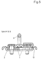
- Fig. 8 shows a preferred embodiment of the invention in a section through Fig. 1 along the line A - A.
- the illustration shows that between the Carrier plates 3, 4 vulcanized rubber layer 1, the rubber layer 1 from the first support plate 3 on both sides with a side bevel 16 is embraced.
- Each side slope 16 closes with the imaginary Extension of the first support plate 3 an angle 17.
- the side slopes 16 forms a lateral guide acting in the direction 5 of the tensile load.
- the retaining eyelet 10 engages the striker 9 with the entire design press area. It is prevented the retaining eyelet is worked into the striker by tilting it to the side.
- Fig. 2 shows a section through a simplified schematic representation a preferred embodiment.
- the first support plate 3 is on the Body 23 set. It has an opening 15, which through Sections of the second support plate 4 is reached.
- the striker 9 is attached on the support plate 4 .
- a rubber layer 1 is between the support plates 3, 4 vulcanized. Seen in the pulling direction 5, this has a front of the Snap lock 8 lying portion 1.2 and one after Snap closure 8 arranged portion 1.1.
- Through each other Thoroughly designed support plates is the one acting in direction 5 Tensile load in a shear / pressure load of the elastomer body 1.1 and 1.2 implemented.
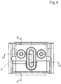
- FIGS. 3 to 6 show a particularly preferred one Embodiment of the invention.
- This embodiment combines the above operating principles explained and shown in Fig. 1 and Fig. 2.
- the Collar screw 17 also serves as a break protection in the event of overload or Crash.
- the striker 9 is under an elastic tensile load in a FIG. 6 snap-in eyelet, not shown. This tensile load is in Fig. 6 by the arrow labeled Fx 5 on one leg of the Strike bar attacks, shown.
- the resilient Relative movement between the striker and body is determined by a Rubber layer 1, which in a, between the support plates 3 and 4th formed gap is vulcanized.
- the support plate 3 has a Opening 15 on.
- the second support plate 4 passes through this Opening 15.
- Both support plates 3, 4 are at a distance from one another arranged. When viewed in the direction of the train, they delimit in front or a gap arranged behind the snap fastener, in which a portion 1.2 or 1.1 of the rubber layer is vulcanized. The tensile load on the snap lock results in a elastic deformation of the two parts 1.1 and 1.2 of the rubber layer.
- a shear load acts on each of these parts and - due to the cross-trained support plates - one Compression. But since the shear modulus is about the elastomer acts by a factor of 1000 less than the compression modulus the relative displacement of the striker with different sizes, counter elastic deformation forces. As a result of this Deformation forces slides the support plate 4 of the ramp 6 of the Support plate 3 high. Seen in the pulling direction in front of the snap lock the support plate 3 slides down the run-down slope 7 of the support plate 4, whereby a tilting of the striker in the direction of the strain is counteracted. On the striker acts - in Figure 6 in the direction clockwise torque.
- the invention enables that Specialist by suitable choice of the material properties of the Elastomer and by appropriate design of Bump 6 and bump 7 that the striker during Snap and only in the closed position opposite the retaining eyelet a tilt angle 2 limited to a few fractions of an angular degree tilts. Since the locking elements do not tilt, the size increases Durability of the locking mechanism. Because the striker is not in If the door tilts towards the hinge, there is no approach of the door leaf in the area of the locking elements. In the closed Position the door wing is equal to the cutout of the body kept a large distance. This reduces sealing problems and the one running in the gap between the body and the door Elastomer seals can be made more cost-effectively. In the case of FIG. 3 to Fig.
- the 6 embodiment of the invention is a leg of Striker 9 in a recess 13 of a cross member 11 of the first Support plate 3.
- a tailgate can act as a damper mass Driving noises appear in the interior without causing an increased Wear occurs between the locking bracket and the retaining eye.
- the second support plate 4 in Provide the area of the rubber layer 1.2 with a bevel, which with the Support plate 3 forms a stop.
- a vibration-decoupled tailgate door according to the state of the Technology is shown in Figure 7.
- the tailgate 21 is over the hinge 22 hinged to a body 23 attached.
- the door leaf 21 is in the closed position by the lock 24 with striker 26 and Lock cylinder 25 held.
- the tailgate 21 acts as an absorber mass and affects the annoying, especially occurring in combination vehicles against interior noise.
Landscapes
- Engineering & Computer Science (AREA)
- General Engineering & Computer Science (AREA)
- Chemical & Material Sciences (AREA)
- Combustion & Propulsion (AREA)
- Physics & Mathematics (AREA)
- Acoustics & Sound (AREA)
- Aviation & Aerospace Engineering (AREA)
- Mechanical Engineering (AREA)
- Lock And Its Accessories (AREA)
Applications Claiming Priority (2)
| Application Number | Priority Date | Filing Date | Title |
|---|---|---|---|
| DE2000144137 DE10044137C2 (de) | 2000-09-06 | 2000-09-06 | Schnappverschluss für eine Fahrzeugtür |
| DE10044137 | 2000-09-06 |
Publications (2)
| Publication Number | Publication Date |
|---|---|
| EP1186737A2 true EP1186737A2 (fr) | 2002-03-13 |
| EP1186737A3 EP1186737A3 (fr) | 2003-10-08 |
Family
ID=7655330
Family Applications (1)
| Application Number | Title | Priority Date | Filing Date |
|---|---|---|---|
| EP01121340A Withdrawn EP1186737A3 (fr) | 2000-09-06 | 2001-09-06 | Porte de véhicule |
Country Status (2)
| Country | Link |
|---|---|
| EP (1) | EP1186737A3 (fr) |
| DE (1) | DE10044137C2 (fr) |
Cited By (2)
| Publication number | Priority date | Publication date | Assignee | Title |
|---|---|---|---|---|
| DE102004020648A1 (de) * | 2004-04-22 | 2005-11-17 | Volkswagen Ag | Schließeinrichtung einer Fahrzeugklappe |
| DE102010049345A1 (de) * | 2010-10-23 | 2012-04-26 | Audi Ag | Schließbügelanordnung für ein Fahrzeugtürschloss |
Families Citing this family (3)
| Publication number | Priority date | Publication date | Assignee | Title |
|---|---|---|---|---|
| DE10305532A1 (de) * | 2003-02-11 | 2004-08-19 | Adam Opel Ag | Schwingungstilgende Befestigung |
| DE102006002972B4 (de) * | 2006-01-20 | 2017-02-09 | Audi Ag | Schließbügel |
| DE102022107879A1 (de) | 2022-04-01 | 2023-10-05 | Vibracoustic Se | Schließbügelentkopplung für einen Schließmechanismus einer Fahrzeugklappe |
Citations (2)
| Publication number | Priority date | Publication date | Assignee | Title |
|---|---|---|---|---|
| DE19524160C1 (de) | 1995-07-03 | 1996-11-28 | Daimler Benz Ag | Kraftfahrzeugkarosserie für einen Kombi-Personenkraftwagen |
| DE19548282A1 (de) | 1995-12-22 | 1997-06-26 | Freudenberg Carl Fa | Heckklappe eines Kraftfahrzeugs |
Family Cites Families (7)
| Publication number | Priority date | Publication date | Assignee | Title |
|---|---|---|---|---|
| DE8710288U1 (de) * | 1987-07-28 | 1987-09-17 | Kiekert GmbH & Co KG, 5628 Heiligenhaus | An einem Türpfosten eines Kraftfahrzeuges zu befestigender Schließkeil für einen Kraftfahrzeugtürverschluß |
| DE4306151C2 (de) * | 1993-02-27 | 1997-12-04 | Kiekert Ag | Aus Stahlblech und Kunststoff aufgebauter Schloßhalter für einen Kraftfahrzeugtürverschluß |
| DE19645506B4 (de) * | 1995-11-25 | 2016-09-08 | Volkswagen Ag | Schließeinrichtung |
| DE19732365B4 (de) * | 1997-07-28 | 2006-03-23 | Volkswagen Ag | Schließbolzenanordnung für eine Heckklappe eines Steilheck-Fahrzeugs |
| IT1293661B1 (it) * | 1997-07-31 | 1999-03-08 | Roltra Morse Spa | Scontrino per una serratura di un veicolo |
| FR2772820B1 (fr) * | 1997-12-22 | 2000-02-11 | Valeo Systemes De Fermetures | Procede de fixation, sur la carrosserie, d'une gache de serrure de vehicule automobile, et sous-ensemble de gache pour la mise en oeuvre dudit procede |
| DE29905848U1 (de) * | 1999-03-31 | 1999-07-29 | GRIWE Innovative Umformtechnik GmbH, 56457 Westerburg | Rastvorrichtung für Autotürschlösser |
-
2000
- 2000-09-06 DE DE2000144137 patent/DE10044137C2/de not_active Expired - Fee Related
-
2001
- 2001-09-06 EP EP01121340A patent/EP1186737A3/fr not_active Withdrawn
Patent Citations (2)
| Publication number | Priority date | Publication date | Assignee | Title |
|---|---|---|---|---|
| DE19524160C1 (de) | 1995-07-03 | 1996-11-28 | Daimler Benz Ag | Kraftfahrzeugkarosserie für einen Kombi-Personenkraftwagen |
| DE19548282A1 (de) | 1995-12-22 | 1997-06-26 | Freudenberg Carl Fa | Heckklappe eines Kraftfahrzeugs |
Cited By (4)
| Publication number | Priority date | Publication date | Assignee | Title |
|---|---|---|---|---|
| DE102004020648A1 (de) * | 2004-04-22 | 2005-11-17 | Volkswagen Ag | Schließeinrichtung einer Fahrzeugklappe |
| DE102004020648B4 (de) * | 2004-04-22 | 2016-08-04 | Volkswagen Ag | Schließeinrichtung einer Fahrzeugklappe |
| DE102010049345A1 (de) * | 2010-10-23 | 2012-04-26 | Audi Ag | Schließbügelanordnung für ein Fahrzeugtürschloss |
| DE102010049345B4 (de) * | 2010-10-23 | 2017-03-16 | Audi Ag | Schließbügelanordnung für ein Fahrzeugtürschloss |
Also Published As
| Publication number | Publication date |
|---|---|
| DE10044137C2 (de) | 2003-07-10 |
| DE10044137A1 (de) | 2002-04-04 |
| EP1186737A3 (fr) | 2003-10-08 |
Similar Documents
| Publication | Publication Date | Title |
|---|---|---|
| EP2018301B1 (fr) | Boîtier pouvant être fixé sur un véhicule automobile, à fonction intégrée de protection des piétons | |
| DE3600845C2 (de) | Gasfeder-Gewichtsausgleichseinrichtung | |
| DE7737712U1 (de) | Vorspannbares Lagerelement | |
| DE60203386T2 (de) | Befestigung eines zubehörteils auf ein kraftfahrzeug | |
| DE102017106019B4 (de) | Schwingungstilger mit Auslenkungsbegrenzern für seine an zwei Enden elastisch gelagerte Tilgermasse | |
| DE19732365B4 (de) | Schließbolzenanordnung für eine Heckklappe eines Steilheck-Fahrzeugs | |
| DE10062500C2 (de) | Fahrzeugtür | |
| DE10043931A1 (de) | Haubenscharnier | |
| DE10044137C2 (de) | Schnappverschluss für eine Fahrzeugtür | |
| EP0487972A2 (fr) | Amortisseur d'oscillations | |
| EP0229940B1 (fr) | Support élastique pour le montage d'une cabine de chauffeur de camion | |
| DE19645506B4 (de) | Schließeinrichtung | |
| DE2826923A1 (de) | Elastisches motorlager, insbesondere fuer kraftfahrzeuge | |
| DE102007032681A1 (de) | Betätigungsvorrichtung für ein Schaltgetriebe eines Kraftfahrzeuges | |
| DE102008016057B4 (de) | Aufstieg für einen Lastkraftwagen | |
| DE102019212696A1 (de) | Achsaufhängung für ein Fahrzeug | |
| DE102004062629B4 (de) | Abdeckung an einem Vorderwagen eines Fahrzeuges | |
| DE3432768C2 (fr) | ||
| EP0191336A1 (fr) | Ensemble composé d'un outil de frappe et d'une unité de support | |
| DE102018203762A1 (de) | Anordnung zur Schwingungsisolierung bowdenzugbetätigter Komponenten | |
| WO2008138528A1 (fr) | Charnière de porte de véhicule automobile conçue pour des portes et des hayons | |
| WO2007031069A2 (fr) | Miroir reglable | |
| DE19547714C2 (de) | Schwingungstilgeranordnung | |
| DE102005026501B4 (de) | Bauteil für einen Schließmechanismus eines Kraftfahrzeuges | |
| WO2023186392A1 (fr) | Accouplement de support de verrouillage pour un mécanisme de verrouillage d'un volet de véhicule |
Legal Events
| Date | Code | Title | Description |
|---|---|---|---|
| PUAI | Public reference made under article 153(3) epc to a published international application that has entered the european phase |
Free format text: ORIGINAL CODE: 0009012 |
|
| AK | Designated contracting states |
Kind code of ref document: A2 Designated state(s): AT BE CH CY DE DK ES FI FR GB GR IE IT LI LU MC NL PT SE TR |
|
| AX | Request for extension of the european patent |
Free format text: AL;LT;LV;MK;RO;SI |
|
| PUAL | Search report despatched |
Free format text: ORIGINAL CODE: 0009013 |
|
| AK | Designated contracting states |
Kind code of ref document: A3 Designated state(s): AT BE CH CY DE DK ES FI FR GB GR IE IT LI LU MC NL PT SE TR |
|
| AX | Request for extension of the european patent |
Extension state: AL LT LV MK RO SI |
|
| AKX | Designation fees paid | ||
| REG | Reference to a national code |
Ref country code: DE Ref legal event code: 8566 |
|
| STAA | Information on the status of an ep patent application or granted ep patent |
Free format text: STATUS: THE APPLICATION IS DEEMED TO BE WITHDRAWN |
|
| 18D | Application deemed to be withdrawn |
Effective date: 20040401 |