EP1186702A2 - Verfahren zur Bahnrissüberwachung - Google Patents
Verfahren zur Bahnrissüberwachung Download PDFInfo
- Publication number
- EP1186702A2 EP1186702A2 EP01115900A EP01115900A EP1186702A2 EP 1186702 A2 EP1186702 A2 EP 1186702A2 EP 01115900 A EP01115900 A EP 01115900A EP 01115900 A EP01115900 A EP 01115900A EP 1186702 A2 EP1186702 A2 EP 1186702A2
- Authority
- EP
- European Patent Office
- Prior art keywords
- web
- impingement
- material web
- dryer
- impingement dryer
- Prior art date
- Legal status (The legal status is an assumption and is not a legal conclusion. Google has not performed a legal analysis and makes no representation as to the accuracy of the status listed.)
- Granted
Links
- 238000000034 method Methods 0.000 title claims abstract description 37
- 239000000463 material Substances 0.000 claims abstract description 111
- 238000012544 monitoring process Methods 0.000 claims abstract description 51
- 238000001035 drying Methods 0.000 claims description 27
- 230000009849 deactivation Effects 0.000 claims description 18
- 239000000123 paper Substances 0.000 claims description 15
- 238000012546 transfer Methods 0.000 claims description 12
- 239000004744 fabric Substances 0.000 claims description 11
- 238000004519 manufacturing process Methods 0.000 claims description 8
- 239000011111 cardboard Substances 0.000 claims description 7
- 239000011087 paperboard Substances 0.000 claims description 7
- 230000003287 optical effect Effects 0.000 claims description 5
- 230000001960 triggered effect Effects 0.000 claims description 4
- 238000011156 evaluation Methods 0.000 claims description 3
- 238000001514 detection method Methods 0.000 description 7
- 238000013021 overheating Methods 0.000 description 3
- 239000011888 foil Substances 0.000 description 2
- 241000792859 Enema Species 0.000 description 1
- 230000001419 dependent effect Effects 0.000 description 1
- 239000007920 enema Substances 0.000 description 1
- 229940095399 enema Drugs 0.000 description 1
- 238000012856 packing Methods 0.000 description 1
- 238000011144 upstream manufacturing Methods 0.000 description 1
Images


Classifications
-
- D—TEXTILES; PAPER
- D21—PAPER-MAKING; PRODUCTION OF CELLULOSE
- D21F—PAPER-MAKING MACHINES; METHODS OF PRODUCING PAPER THEREON
- D21F5/00—Dryer section of machines for making continuous webs of paper
-
- D—TEXTILES; PAPER
- D21—PAPER-MAKING; PRODUCTION OF CELLULOSE
- D21F—PAPER-MAKING MACHINES; METHODS OF PRODUCING PAPER THEREON
- D21F5/00—Dryer section of machines for making continuous webs of paper
- D21F5/18—Drying webs by hot air
-
- D—TEXTILES; PAPER
- D21—PAPER-MAKING; PRODUCTION OF CELLULOSE
- D21F—PAPER-MAKING MACHINES; METHODS OF PRODUCING PAPER THEREON
- D21F5/00—Dryer section of machines for making continuous webs of paper
- D21F5/18—Drying webs by hot air
- D21F5/182—Drying webs by hot air through perforated cylinders
-
- D—TEXTILES; PAPER
- D21—PAPER-MAKING; PRODUCTION OF CELLULOSE
- D21F—PAPER-MAKING MACHINES; METHODS OF PRODUCING PAPER THEREON
- D21F7/00—Other details of machines for making continuous webs of paper
- D21F7/04—Paper-break control devices
Definitions
- the invention relates to a method for web break monitoring in one of the Production of a material web, in particular paper or cardboard web, serving machine. It also relates to a machine for producing a Material web, in particular paper or cardboard web, in which such Web break monitoring is realized.
- a tear detection is usually carried out on the paper machine Driver and drive side in several positions in the machine direction inside the cylinder dryer section. Such a tear detection serves to prevent an uncontrolled amount of paper in the dryer section and to avoid so-called packing of cylinders. A respective one Tear detection triggers a discount on the paper web or a take off the pickup roller.
- the aim of the invention is now the method and the machine of the beginning mentioned type so that despite the use of one or multiple impingement dryers the risk of such damage to the Dryer fabrics is practically eliminated.
- the material web is preferably viewed in the web running direction directly before entering the impingement dryer and / or directly after discharge from the impingement dryer and / or between several impingement dryers monitored for demolition.
- the material web is at least essentially above its process monitored across the entire width for a tear.
- Such a web width Monitoring also detects when only parts of the web are missing that overheating of the dryer fabrics is also avoided in places.
- the material web only a tear on one or on the two side edges of the web is monitored. It is therefore basically a surveillance only the edges of the track on the guide and drive side are conceivable.
- a respective impingement dryer with at least one Provide impingement hood If a web break is detected, this is preferred at least one each of the impingement dryer in question assigned impingement hood deactivated.
- Impimgementhaube away from the normal web run it is also possible for a respective deactivation the Impimgementhaube away from the normal web run to move into a transfer line.
- the impingement dryer should be deactivated within 20s, preferably within 10s after a web break so that it no overheating even at air temperatures of 300 - 500 ° C Dryer fabrics is coming.
- the procedure is next to the at least partial deactivation of the impingement dryer at the same time at least one upstream of the impingement dryer and / or before and / or in the press section provided pickup point opened. This should be done within 5s, preferably less than 2s after a web break.
- the material web at least at one point on at least one sensor Demolition monitored.
- the use of sensors is different kind of imaginable.
- at least one is optical Sensor used.
- a respective web break can in particular by color recognition or by using a camera Image evaluation can be captured.
- At least one sensor is preferred directly after a respective impingement hood onto the material web is judged.
- the sensor can, for example, in an area on the material web be directed in which this is still on one by the concerned Impingement dryer guided dryer fabric lies.
- This vacuumed roller can be, for example Act a suction roller or a so-called "DuoStabi roller".
- the dryer fabrics are preferably made of plastic, the maximum permissible temperature is between 100 and 300 ° C. However, should Temperatures between 300 and 500 ° C during the deactivation of the Impingement dryer will not damage the dryer fabric.
- the sensor in the area of a first on the impingement dryer following drying cylinder towards the material web straighten, in which the material web after the expiry of a previous one Siebes and before the emergence of a new sieve, whereby the Sensor is directed to the exposed railway station.
- the sensor can thus directed towards the first cylinder after the impingement dryer when there is a group change on this cylinder which results in a place where the paper web is exposed.
- the material web in the area of one suctioned after the impingement dryer Roller or one of the large suction rollers of the impingement dryer by monitoring the vacuum of this vacuumed roller is monitored.
- the vacuum drops sharply as soon as the roller does not more of the material web, in particular paper web, is covered.
- This is sucked Roll preferably within those following the impingement dryer provided first cylinder group. It can be viewed in the direction of web travel in particular, be provided in front of an acceptance scraper. It may be the first one following the impingement dryer act vacuumed roller.
- the vacuumed rollers that are monitored can also be the big ones Suction rollers on which the impingement hoods are mounted.
- the material web is moved in the area of an impingement dryer monitored for a demolition between a press section and a cylinder dryer section of the production of a material web serving machine is arranged.
- the material web can, for example, in the area of an impingement dryer be monitored for a demolition in which the material web at least partially along a straight or slightly curved one and / or on at least one, in particular larger, preferably vacuumed backup roller is guided.
- a machine for producing a material web is also in particular paper or cardboard web, proposed in the the material web passed through at least one impingement dryer is and means are provided to the material web in the web running direction viewed in the area before entering the impingement dryer and / or in the area after discharge from the impingement dryer to monitor for a demolition, and funds are provided to the impingement dryer at least partially when a web break is detected to deactivate.
- the demolition monitoring means preferably comprise at least one Sensor to at least the material web at least at one point monitor such a sensor for a tear.
- Machine include the demolition monitoring means and / or the Deactivation means at least one electronic control.
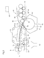
- Figure 1 shows a purely schematic representation of a dryer section 10 of a Machine for producing a material web 12, which is in particular can be a paper or cardboard web.
- the pickup suction roller 20 is wrapped in a sieve 24.
- the impingement dryer 18 comprises one of a larger support roller 26 assigned, in this case one-piece impingement hood 28. Die Material web 12 is through the pick-up suction roller 20 onto the support roller 26 handed over to this impingement drying unit.
- the support roller 26 is surrounded by a screen 30 and formed by a suction roll, which here is an outer suction box 32 assigned.
- the takeover of the material web 12 by the large support roller 26 is by a distance L behind the pickup suction roller in the direction of web travel 20 arranged, provided within the loop of the sieve 24 Deflection roller 34 supports. After this guide roller 34 on the Support roller 26 abuts, the screen 24 and thus the material web 12 in Area between the pickup suction roller 20 and the deflection roller 34 the support roller 26 created.
- the material web 12 is in the area a suction roller 36 from the screen 38 of a first multi-cylinder group 40 several drying cylinders 42 taken over. The takeover takes place so that in the event of a tear between the sieves 30 and 38 can fall into the basement 44.
- the material web 12 is in the direction of web travel L considered in the area before the inlet 41 into the impingement dryer 18 and / or in the area after the outlet 42 from the impingement dryer 18 monitored for a break in order to detect a web break to at least partially deactivate the impingement dryer 18.
- the material web 12 can be viewed directly in the web running direction L. before the inlet 41 into the impingement dryer 18 and / or directly after the outlet 42 from the impingement dryer 18 on a demolition be monitored.
- the relevant monitoring points are shown in FIG designated S1 and S2.
- FIG. 1 it can be additionally or alternatively also in the area of the first ones following the impingement dryer 18 vacuumed roller, here the suction roller 36, a corresponding web break monitoring respectively.
- the monitoring point in question is designated S3.
- the material web 12 At a respective monitoring point S1 - S3, the material web 12 at least essentially across the entire width for a tear be monitored.
- tear-off monitoring is also essential only possible on one or on the two side edges of the web.
- the impingement dryer is used in the present case 18 associated impingement hood 28 deactivated. This can this in particular from a normal operating state in which the Material web 12 with a hot air and / or hot steam impingement flow is applied to be reversed into a demolition mode that only a hood-internal hot air or hot steam circulation occurs.
- the impingement hood 28 can be deactivated from the normal web running route, i.e. here from the support roller 26 be moved away to a web transfer position.
- the web break is detected, in addition to the at least partial deactivation of the impingement dryer at the same time in particular Material web or paper discount are triggered. Basically it is also possible, at the same time as the at least partial deactivation of the Impingement dryer 18 at least one in the web running direction L before to open the picking point provided for the impingement dryer 18.
- the material web 12 can be at least by means of of a sensor 46 are monitored for a tear.
- a sensor 46 there
- at least one optical sensor can be used.
- a respective web break for example is detected by a color recognition.
- Both at the monitoring point provided in front of the impingement hood 28 S1 as well as directly on the impingement hood 28 subsequent monitoring point S2 can be a respective sensor for example, be directed directly at the material web 12. It is the respective sensor 46 is directed towards the material web 12 in one area, in which this is already or still on the impingement dryer 18 guided dryer fabric 30 is.
- a respective sensor 46 can also be used at the monitoring point S3 be directed to the material web 12.
- the material web lies 12 on the dryer wire 38 following the impingement dryer 18 provided first vacuumed roller, here the suction roller 36th
- the material web 12 at the monitoring point S3 by monitoring the vacuum of the vacuumed roller, here the suction roller 36 to monitor.
- Which comprise the sensors 46 or the vacuum monitoring means Demolition monitoring means and / or the deactivation means comprise in the present case at least one electronic control 48.
- the material web 12 is in the area of an impingement dryer 18 monitored for a demolition between the press section 16 and the multi-cylinder group or cylinder dryer section 40 arranged for the production of the material web 12 machine is.
- a respective tear-off monitoring can also be carried out on one within the first cylinder group following the impingement dryer 18 40 provided suction roll.
- the relevant vacuumed roller can in the web running direction L in front of one Acceptance scraper be provided.
- the embodiment according to FIG. 2 differs from the previously described embodiment essentially in that the impingement dryer 18 provided after the last press nip 14 is followed by another impingement dryer 18 '.
- This second impingement dryer 18 ' comprises a two-part impingement hood 28', again assigned to a larger support roller 26 '.
- the support roller 26 ' is again formed by a suction roller to which, for example, an outer suction box 32' is assigned.
- the diameters of the two support rollers 26, 26 ' are at least essentially the same size.
- the second support roller 26 ' is wrapped in a first screen 38 of the cylinder dryer section 40.
- the web of material 12 is Sieve 30 of the first impingement dryer 18 directly to that of Sieve 38 wrapped large support roller 26 'of the second following Hand over impingement dryer 18 '.
- the large backup roller 26 ' is obliquely below the large backup roller 26 arranged.
- the impingement hood 28 of the first impingement dryer 18 generally provided above the associated support roller 26 is the two-part impingement hood 28 'of the following one second impingement dryer 18 'generally below the assigned large backup roller 26 arranged.
- tear monitoring is possible, for example, at a point S1 ′ immediately after the first impingement hood 18.
- tear-off monitoring is possible at a point S2 'immediately following the impingement hood 28' of the two-part impingement dryer 18 '.
- the relevant tear-off monitoring takes place here between the two impingement hoods 28 'assigned to the support roller 26.
- a tear-off monitoring at a point S3 'in the area of the outlet 52 of the screen 38 from the support roller 26' is also conceivable.
- a respective sensor 46 can detect the total with the screen 38 guided over the support roller 26 'web 12 be directed.
- a respective sensor 46 can detect the still material web lying on the screen 38 running off the support roller 26 26 be directed.
- a respective sensor can be shown in FIG Way in the area of a first impingement dryer 18 ' following drying cylinder 54 to be directed onto the material web 12 at the material web after the preceding screen 38 has passed and is exposed before the opening of a new screen 56, the sensor 46 is directed to the exposed station 58.
- FIG. 2 has at least essentially again the same structure as that of Figure 1, with each other corresponding parts are assigned the same reference numerals. Also the respective demolition monitoring at the relevant points can otherwise done again as before, for example based on the embodiment was described according to Figure 1.
- the material web 12 starts out from the last press nip 14 of the press section 16 via at least one straight or slightly curved route 60 in a closed train to one in particular larger backup roller 62 with associated impingement dryer 64 passed through which the material web guided over the support roller 62 12 can be acted upon with a hot air and / or hot steam impingement flow is, the straight or slightly curved path 60 as Impingement drying and / or as a transfer foil route with an assigned Impingement dryer 61 is provided.
- the impingement dryer 61 can, for example, again with at least one impingement hood 61 '.
- the impingement dryer 64 has again a two-part impingement hood 64 '.
- Figure 3 shows an embodiment with a straight after the or slightly curved path 60 provided lower larger backup roller 62 with associated impingement dryer 64 Back-up roller 62 in front of a drying group 66 with at least one drying cylinder 68 arranged.
- the material web 12 is in the straight or slightly curved path 60 guided between two screens 70, 72.
- the material web 12 is, for example from the top by means of the impingement dryer 61 impinged with a baffle flow through the relevant screen 72. Also this impingement dryer 61, which again with at least an impingement hood 61 'can be provided when the web break is detected can be deactivated again accordingly.
- the material web 12 is moved from the lower by means of a pick-up roller 74 taken through the press nip 14 press felt 22 on the screen 72.
- the material web 12 is in the region of an additional pickup roller 76 the basement 44 mobile, by means of which the web of material 12 from the press felt or press belt 22 is removable.
- the screen 70 of the impingement drying or transfer film section 60 is guided in front of the larger support roller 62 via a smaller suction roller 78.
- a smaller suction roll can serve as an overpressure zone be formed, or an overpressure box is installed in the intermediate space, around the material web 12 from the previous screen, here the screen 70, pull the trigger.
- the material web 12 is of the wire 70 of the straight or slightly curved Impingement drying or transfer foil section 60 transfer a screen 80 guided over the following larger backup roller 62, the transfer area, for example, by means of a front or on the Support roller 62 provided suction box can be sucked.
- the web break monitoring can, for example, on a Place S1 "'in the area of the suction roller 78. This area lies the web of material 12 after the sieve 72 has been lifted off and before it emerges of the sieve 80 free. A respective sensor 46 can thus directly again be directed to the material web 12.
- web break monitoring can also be carried out at a point S2 "'in the area of the outlet 82 of the screen 80 from the support roller 62.
- the material web 12 carried by the screen 80 is also exposed in this area, so that a respective sensor 49 is directly on again the material web 12 can be directed.
- web break monitoring can also be carried out here again, for example, as described for example in connection with the embodiment according to FIG. 1.
- the tear-off monitoring means 46 and / or the deactivation means can again comprise at least one electronic control 48.
- the pickup roller 74 in particular can be lifted off the press felt 22 at the same time.
- tear monitoring of the paper web is, for example possible immediately after impingement drying.
- tear detection not only triggers the pick-up roller or the paper discount, it also controls the impingement hood on demolition, which can mean in particular that switched to an internal circulation of hot air, the burner on Minimum output changed and / or the hood into a transfer position is driven.
- impingement hood on demolition can mean in particular that switched to an internal circulation of hot air, the burner on Minimum output changed and / or the hood into a transfer position is driven.
- With web-wide monitoring it is also recognized if only parts of the web are missing, so that a partial overheating the dryer fabric is avoided.
- the monitoring can take place by means of various sensors, whereby In particular, optical sensors can be used, for example carry out monitoring by color detection.
- a possible position for the monitoring results in particular directly after the impingement hood, where a respective sensor directly on the paper web is directed, which is still on the dryer, for example while the web on the dryer fabric of the subsequent suction roll or "DuoStabi roller".
- the sensor on the first cylinder is directed after the impingement dryer, and in particular if there is a change of group on this cylinder takes place. With such a group change there is one Place where the paper web is exposed after the previous sieve is lifted off and before the new sieve hits the cylinder.
- a respective tear detection is also possible in that the Vacuum of the first vacuumed roller after the impingement dryer is monitored.
- the vacuum drops sharply as soon as the roller does not is more paper covered.
- the monitored vacuumed roller can be a suction roller or a so-called "DuoStabi roller" and should expediently within the first cylinder group after the impingement dryer, preferably in front of the take-off scraper.
- the monitored roller can also be one of the large vacuumed rollers of the Be impingement dryer, for example several of these Rolls large suctioned rolls can be monitored accordingly.
- the demolition detection can be done with an impingement dryer between the Press section and a cylinder dryer section or with an impingement dryer can be combined within the dryer section.
- the impingement dryer can be straight or on a large, preferably vacuumed roller. Basically, too any combination of several of the one and / or other variant conceivable.
Landscapes
- Paper (AREA)
- Preliminary Treatment Of Fibers (AREA)
Abstract
Description
- Figur 1
- eine schematische Darstellung einer ersten Ausführungsform einer Trockenpartie mit nur einem Impingement-Trockner,
- Figur 2
- eine schematische Darstellung einer weiteren Ausführungsform einer Trockenpartie mit zwei Impingement-Trocknern und
- Figur 3
- eine schematische Darstellung einer weiteren Ausführungsform einer Trockenpartie mit einer geraden oder leicht gekrümmten Impingementtrocknungs-Strecke und einer unteren größeren Stützwalze mit zugeordnetem Impingement-Trockner.
Dieser zweite Impingement-Trockner 18' umfaßt eine wieder einer größeren Stützwalze 26' zugeordnete zweiteilige Impingementhaube 28'. Auch in diesem Fall ist die Stützwalze 26' wieder durch eine Saugwalze gebildet, der beispielsweise ein äußerer Saugkasten 32' zugeordnet ist. Im vorliegenden Fall sind die Durchmesser der beiden Stützwalzen 26, 26' zumindest im wesentlichen gleich groß. Die zweite Stützwalze 26' ist von einem ersten Sieb 38 der Zylinder-Trockenpartie 40 umschlungen.
Alternativ oder zusätzlich ist auch eine Abrißüberwachung an einer Stelle S3' im Bereich des Ablaufs 52 des Siebes 38 von der Stützwalze 26' denkbar.
Ebenso wie bei der Ausführungsform gemäß Figur 2 kann auch hier die Bahnrißüberwachung im übrigen beispielsweise wieder so erfolgen, wie dies beispielsweise im Zusammenhang mit der Ausführungsform gemäß Figur 1 beschrieben wurde. Auch hier können die Abrißüberwachungsmittel 46 und/oder die Deaktivierungsmittel wieder wenigstens eine elektronische Steuerung 48 umfassen. Neben der Deaktivierung des Impingement-Trockners 64 kann hier bei erkanntem Bahnabriß gleichzeitig insbesondere auch die Pickup-Walze 74 von dem Preßfilz 22 abgehoben werden.
- 10
- Trockenpartie
- 12
- Materialbahn
- 14
- Preßnip
- 16
- Pressenpartie
- 18
- Impingement-Trockner
- 18'
- Impingement-Trockner
- 20
- Pickup-Saugwalze
- 22
- Preßfilz
- 24
- Sieb
- 26
- größere Stützwalze
- 26'
- größere Stützwalze
- 28
- Impingementhaube
- 28'
- zweiteilige Impingementhaube
- 30
- Sieb
- 32
- Saugkasten
- 32'
- Saugkasten
- 34
- Umlenkwalze
- 36
- Saugwalze
- 38
- Sieb
- 40
- Mehrzylindergruppe, Zylinder-Trockenpartie
- 41
- Einlauf
- 42
- Auslauf
- 44
- Keller
- 46
- Sensor
- 48
- Walze
- 52
- Ablauf
- 54
- Trockenzylinder
- 56
- Sieb
- 58
- freiliegende Bahnstelle
- 60
- gerade oder leicht gekrümmte Impingement-Strecke
- 61
- Impingement-Trockner
- 61'
- Impingementhaube
- 62
- größere Stützwalze
- 64
- Impingement-Trockner
- 64'
- zweiteilige Impingementhaube
- 66
- Trockengruppe
- 68
- Trockenzylinder
- 70
- Sieb
- 72
- Sieb
- 74
- Pickup-Walze
- 76
- Pickup-Walze
- 78
- Saugwalze
- 80
- Sieb
- 82
- Ablauf
- L
- Bahnlaufrichtung
- S1 - S3
- Überwachungsstelle
- S1' - S4'
- Überwachungsstelle
- S1"' - S2"'
- Überwachungsstelle
Claims (52)
- Verfahren zur Bahnrißüberwachung in einer der Herstellung einer Materialbahn (12), insbesondere Papier- oder Kartonbahn, dienenden Maschine, in der die Materialbahn (12) durch wenigstens einen Impingement-Trockner (18, 18', 61, 64) geführt wird, wobei die Materialbahn (12) in Bahnlaufrichtung (L) betrachtet im Bereich vor dem Einlauf (40) in den Impingement-Trockner und/oder im Bereich nach dem Auslauf (42) aus dem Impingement-Trockner und/oder innerhalb des Impingement-Trockners auf einen Abriß hin überwacht und der Impingement-Trockner bei erkanntem Bahnabriß zumindest teilweise deaktiviert wird.
- Verfahren nach Anspruch 1,
dadurch gekennzeichnet, daß die Materialbahn (12) in Bahnlaufrichtung (L) betrachtet direkt vor dem Einlauf (41) in den Impingement-Trockner (18, 18', 61, 64) und/oder direkt nach dem Auslauf (42) aus dem Impingement-Trockner und/oder zwischen mehreren Impingement-Trocknern auf einen Abriß hin überwacht wird. - Verfahren nach Anspruch 1 oder 2,
dadurch gekennzeichnet, daß die Materialbahn (12) zumindest im wesentlichen über ihre gesamte Breite hinweg auf einen Abriß hin überwacht wird. - Verfahren nach Anspruch 1 oder 2,
dadurch gekennzeichnet, daß die Materialbahn (12) nur an einem oder den seitlichen Bahnrändern auf einen Abriß hin überwacht wird. - Verfahren nach einem der vorhergehenden Ansprüche,
dadurch gekennzeichnet, daß bei erkanntem Bahnabriß wenigstens eine dem Impingement-Trockner (18, 18', 61, 64) zugeordnete Impingementhaube (28, 28', 64') deaktiviert wird. - Verfahren nach Anspruch 5,
dadurch gekennzeichnet, daß zur Deaktivierung der Impingementhaube (28, 28', 61', 64') diese von einem normalen Betriebszustand, bei dem die Materialbahn (12) mit einer Heißluft- und/oder Heißdampfprallströmung beaufschlagt wird, in einen Abrißbetriebszustand umgesteuert wird, bei dem nur noch eine haubeninterne Heißluft- bzw. Heißdampfzirkulation auftritt. - Verfahren nach Anspruch 5 oder 6,
dadurch gekennzeichnet, daß zur Deaktivierung der Impingementhaube (28, 28', 61', 64') ein dieser zugeordneter Brenner auf Minimalleistung umgeschaltet wird. - Verfahren nach einem der vorhergehenden Ansprüche,
dadurch gekennzeichnet, daß zur Deaktivierung der Impingementhaube (28, 28', 61', 64') diese von der normalen Bahnlaufstrecke weg in eine Bahnüberführstellung verfahren wird. - Verfahren nach einem der vorhergehenden Ansprüche,
dadurch gekennzeichnet, daß die Deaktivierung des Impingement-Trockners innerhalb von 20s, vorzugsweise innerhalb von 10s nach einem Bahnabriß erfolgt. - Verfahren nach einem der vorhergehenden Ansprüche,
dadurch gekennzeichnet, daß bei erkanntem Bahnabriß neben der zumindest teilweisen Deaktivierung des Impingement-Trockners (18, 18', 61, 64) gleichzeitig auch wenigstens eine in Bahnlaufrichtung (L) vor dem Impingement-Trockner vorgesehene Pickupstelle (74) geöffnet wird. - Verfahren nach einem der vorhergehenden Ansprüche,
dadurch gekennzeichnet, daß bei erkanntem Bahnabriß neben der zumindest teilweisen Deaktivierung des Impingement-Trockners (18, 18', 61, 64) gleichzeitig auch wenigstens eine in Bahnlaufrichtung (L) vor und/oder in der Pressenpartie (16) vorgesehene Pickupstelle geöffnet wird. - Verfahren nach einem der vorhergehenden Ansprüche,
dadurch gekennzeichnet, daß bei erkanntem Bahnabriß neben der zumindest teilweisen Deaktivierung des Impingement-Trockners (18, 18', 61, 64) gleichzeitig auch ein Materialbahn- bzw. Papierabschlag ausgelöst wird. - Verfahren nach einem der vorhergehenden Ansprüche,
dadurch gekennzeichnet, daß die Materialbahn (12) an zumindest einer Stelle (S1-S3; S1'-S4'; S"', S2"') mittels wenigstens eines Sensors (46) auf einen Abriß hin überwacht wird. - Verfahren nach Anspruch 13,
dadurch gekennzeichnet, daß wenigstens ein optischer Sensor (46) oder eine Kamera verwendet wird. - Verfahren nach Anspruch 14,
dadurch gekennzeichnet, daß ein jeweiliger Bahnabriß durch eine Farberkennung erfaßt wird. - Verfahren nach Anspruch 15,
dadurch gekennzeichnet, daß ein jeweiliger Bahnabriß durch eine Bildauswertung erfaßt wird. - Verfahren nach einem der vorhergehenden Ansprüche,
dadurch gekennzeichnet, daß wenigstens ein Sensor (46) vorzugsweise direkt nach einer jeweiligen Impingementhaube (28, 28', 64') auf die Materialbahn (12) gerichtet wird. - Verfahren nach Anspruch 17,
dadurch gekennzeichnet, daß der Sensor (46) in einem Bereich auf die Materialbahn (12) gerichtet wird, in dem diese noch auf einem durch den betreffenden Impingement-Trockner (18, 18', 61, 64) geführten Trockensieb (30, 38, 70, 80) liegt. - Verfahren nach Anspruch 17,
dadurch gekennzeichnet, daß der Sensor (46) in einem Bereich auf die Materialbahn (12) gerichtet wird, in dem diese auf einem Trockensieb (38) einer im Anschluß an den Impingement-Trockner vorgesehenen besaugten Walze (36) liegt. - Verfahren nach Anspruch 17,
dadurch gekennzeichnet, daß der Sensor (46) im Bereich eines ersten auf den Impingement-Trockner (18') folgenden Trockenzylinders (54) auf die Materialbahn (12) gerichtet wird, bei dem die Materialbahn (12) nach erfolgtem Ablauf eines vorangehenden Siebes (38) und vor dem Auflauf eines neuen Siebes (56) freiliegt, wobei der Sensor (46) auf die freiliegende Bahnstelle (58) gerichtet wird. - Verfahren nach einem der vorhergehenden Ansprüche,
dadurch gekennzeichnet, daß die Materialbahn (12) im Bereich einer auf den Impingement-Trockner (18, 61) folgenden besaugten Walze (36, 78, 48) oder einer der großen besaugten Walzen des Impingement-Trockners durch Überwachen des Unterdrucks dieser besaugten Walze (36, 78, 48) überwacht wird. - Verfahren nach Anspruch 21,
dadurch gekennzeichnet, daß die besaugte Walze (48) innerhalb der auf den Impingement-Trockner (18) folgenden ersten Zylindergruppe (40) vorgesehen ist. - Verfahren nach Anspruch 22,
dadurch gekennzeichnet, daß die besaugte Walze (36, 78) in Bahnlaufrichtung (L) vor einem Abnahmeschaber vorgesehen ist. - Verfahren nach einem der vorhergehenden Ansprüche,
dadurch gekennzeichnet, daß die Materialbahn (12) im Bereich eines Impingement-Trockners (18, 18', 61, 64) auf einen Abriß hin überwacht wird, der zwischen einer Pressenpartie (16) und einer Zylinder-Trockenpartie (40) der der Herstellung der Materialbahn dienenden Maschine angeordnet ist. - Verfahren nach einem der vorhergehenden Ansprüche,
dadurch gekennzeichnet, daß die Materialbahn (12) im Bereich eines Impingement-Trockners auf einen Abriß hin überwacht wird, der innerhalb einer Zylinder-Trockenpartie (40) der der Herstellung der Materialbahn (12) dienenden Maschine angeordnet ist. - Verfahren nach einem der vorhergehenden Ansprüche,
dadurch gekennzeichnet, daß die Materialbahn (12) im Bereich eines Impingement-Trockners (18, 18', 61, 64) auf einen Abriß hin überwacht wird, in dem die Materialbahn (12) zumindest teilweise entlang wenigstens einer geraden oder leicht gekrümmten Strecke (60) und/oder auf wenigstens einer insbesondere größeren, vorzugsweise besaugten Stützwalze (26, 26', 62) geführt ist. - Maschine zur Herstellung einer Materialbahn (12), insbesondere Papier- oder Kartonbahn, in der die Materialbahn (12) durch wenigstens einen Impingement-Trockner (18, 18', 61, 64) geführt ist und Mittel (46) vorgesehen sind, um die Materialbahn (12) in Bahnlaufrichtung (L) betrachtet im Bereich vor dem Einlauf (40) in den Impingement-Trockner und/oder im Bereich nach dem Auslauf (42) aus dem Impingement-Trockner auf einen Abriß hin zu überwachten, sowie Mittel (48) vorgesehen sind, um den Impingement-Trockner bei erkanntem Bahnabriß zumindest teilweise zu deaktivieren.
- Maschine nach Anspruch 27,
dadurch gekennzeichnet, daß die Materialbahn (12) in Bahnlaufrichtung (L) betrachtet direkt vor dem Einlauf (41) in den Impingement-Trockner (18, 18', 61, 64) und/oder direkt nach dem Auslauf (42) aus dem Impingement-Trockner und/oder zwischen mehreren Impingement-Trocknern auf einen Abriß hin überwachbar ist. - Maschine nach Anspruch 27 oder 28,
dadurch gekennzeichnet, daß die Materialbahn (12) zumindest im wesentlichen über ihre gesamte Breite hinweg auf einen Abriß hin überwachbar ist. - Maschine nach Anspruch 27 oder 28,
dadurch gekennzeichnet, daß die Materialbahn (12) nur an einem oder den seitlichen Bahnrändern auf einen Abriß hin überwacht wird. - Maschine nach einem der vorhergehenden Ansprüche,
dadurch gekennzeichnet, daß bei erkanntem Bahnabriß wenigstens eine dem Impingement-Trockner (18, 18', 61, 64) zugeordnete Impingementhaube (28, 28', 61', 64') deaktivierbar ist. - Maschine nach Anspruch 31,
dadurch gekennzeichnet, daß zur Deaktivierung der Impingementhaube (28, 28', 61', 64') diese von einem normalen Betriebszustand, bei dem die Materialbahn (12) mit einer Heißluft- und/oder Heißdampfprallströmung beaufschlagt wird, in einen Abrißbetriebszustand umsteuerbar ist, bei dem nur noch eine haubeninterne Heißluft- bzw. Heißdampfzirkulation auftritt. - Maschine nach Anspruch 31 oder 32,
dadurch gekennzeichnet, daß zur Deaktivierung der Impingementhaube (28, 28', 61', 64') ein dieser zugeordneter Brenner auf Minimalleistung umschaltbar ist. - Maschine nach einem der vorhergehenden Ansprüche,
dadurch gekennzeichnet, daß zur Deaktivierung der Impingementhaube (28, 28', 61', 64') diese von der normalen Bahnlaufstrecke weg in eine Bahnüberführstellung verfahrbar ist. - Maschine nach einem der vorhergehenden Ansprüche,
dadurch gekennzeichnet, daß bei erkanntem Bahnabriß neben der zumindest teilweisen Deaktivierung des Impingement-Trockners gleichzeitig auch wenigstens eine in Bahnlaufrichtung (L) vor dem Impingement-Trockner (18, 18', 61, 64) vorgesehene Pickupstelle (74) geöffnet wird. - Maschine nach einem der vorhergehenden Ansprüche,
dadurch gekennzeichnet, daß bei erkanntem Bahnabriß neben der zumindest teilweisen Deaktivierung des Impingement-Trockners (18, 18', 61, 64) gleichzeitig auch ein Materialbahn- bzw. Papierabschlag auslösbar ist. - Maschine nach einem der vorhergehenden Ansprüche,
dadurch gekennzeichnet, daß die Abrißüberwachungsmittel wenigstens einen Sensor (46) umfassen, um die Materialbahn (12) an zumindest einer Stelle mittels wenigstens eines solchen Sensors (46) auf einen Abriß hin zu überwachen. - Maschine nach Anspruch 37,
dadurch gekennzeichnet, daß die Abrißüberwachungsmittel wenigstens einen optischen Sensor (46) oder eine Kamera umfassen. - Maschine nach Anspruch 38,
dadurch gekennzeichnet, daß ein jeweiliger Bahnabriß durch eine Farberkennung und/oder eine Bildauswertung erfaßbar ist. - Maschine nach einem der vorhergehenden Ansprüche,
dadurch gekennzeichnet, daß wenigstens ein Sensor (46) vorzugsweise direkt nach einer jeweiligen Impingementhaube (28, 28', 61', 64') auf die Materialbahn (12) gerichtet ist. - Maschine nach Anspruch 39,
dadurch gekennzeichnet, daß der Sensor (46) in einem Bereich auf die Materialbahn (12) gerichtet ist, in dem diese noch auf einem durch den betreffenden Impingement-Trockner (18, 18', 61, 64) geführten Trockensieb (30, 38, 70, 80) liegt. - Maschine nach Anspruch 39,
dadurch gekennzeichnet, daß der Sensor (46) in einem Bereich auf die Materialbahn (12) gerichtet ist, in dem diese auf einem Trockensieb (38) einer im Anschluß an den Impingement-Trockner vorgesehenen besaugten Walze (36) liegt. - Maschine nach Anspruch 41 oder 42
dadurch gekennzeichnet, daß das Trockensieb (30, 28, 70, 80) aus Kunststoff besteht, wobei die maximal zulässige Temperatur vorzugsweise zwischen 100°C und 200°C liegt. - Maschine nach Anspruch 39,
dadurch gekennzeichnet, daß der Sensor (46) im Bereich eines ersten auf den Impingement-Trockner (18') folgenden Trockenzylinders (54) auf die Materialbahn (12) gerichtet ist, bei dem die Materialbahn (12) nach erfolgtem Ablauf eines vorangehenden Siebes (38) und vor dem Auflauf eines neuen Siebes (56) freiliegt, wobei der Sensor (46) auf die freiliegende Bahnstelle (58) gerichtet ist. - Maschine nach einem der vorhergehenden Ansprüche,
dadurch gekennzeichnet, daß die Materialbahn (12) im Bereich einer auf den Impingement-Trockner (18, 61) folgenden besaugten Walze (36, 78, 48) durch Überwachen des Unterdrucks dieser besaugten Walze (36, 78, 48) überwachbar ist. - Maschine nach Anspruch 45,
dadurch gekennzeichnet, daß die besaugte Walze (48) innerhalb der auf den Impingement-Trockner (18) folgenden ersten Zylindergruppe (40) vorgesehen ist. - Maschine nach Anspruch 46,
dadurch gekennzeichnet, daß die besaugte Walze (36, 78) in Bahnlaufrichtung (L) vor einem Abnahmeschaber vorgesehen ist. - Maschine nach einem der vorhergehenden Ansprüche,
dadurch gekennzeichnet, daß die Materialbahn (12) im Bereich eines Impingement-Trockners (18, 18', 61, 64) auf einen Abriß hin überwachbar ist, der zwischen einer Pressenpartie (16) und einer Zylinder-Trockenpartie (40) der Maschine angeordnet ist. - Maschine nach einem der vorhergehenden Ansprüche,
dadurch gekennzeichnet, daß die Materialbahn (12) im Bereich eines Impingement-Trockners auf einen Abriß hin überwachbar ist, der innerhalb einer Zylinder-Trockenpartie (40) der Maschine angeordnet ist. - Maschine nach einem der vorhergehenden Ansprüche,
dadurch gekennzeichnet, daß die Materialbahn (12) im Bereich eines Impingement-Trockners (18, 18', 61, 64) auf einen Abriß hin überwachbar ist, in dem die Materialbahn (12) zumindest teilweise entlang wenigstens einer geraden oder leicht gekrümmten Strecke (60) und/oder auf wenigstens einer insbesondere größeren, vorzugsweise besaugten Stützwalze (26, 26', 62) geführt ist. - Maschine nach einem der vorhergehenden Ansprüche,
dadurch gekennzeichnet, daß die Abrißüberwachungsmittel (46) und/oder die Deaktivierungsmittel wenigstens eine elektronische Steuerung (48) umfassen. - Maschine nach einem der vorhergehenden Ansprüche,
dadurch gekennzeichnet,
die Materialbahn in der Pressenpartie (16) gemeinsam mit beidseitig je einem Band in Form eines Preßfilzes (22) oder eines Transferbandes durch den oder die Preßnips (14) geführt wird.
Applications Claiming Priority (2)
| Application Number | Priority Date | Filing Date | Title |
|---|---|---|---|
| DE10042243A DE10042243A1 (de) | 2000-08-28 | 2000-08-28 | Verfahren zur Bahnrißüberwachung |
| DE10042243 | 2000-08-28 |
Publications (4)
| Publication Number | Publication Date |
|---|---|
| EP1186702A2 true EP1186702A2 (de) | 2002-03-13 |
| EP1186702A3 EP1186702A3 (de) | 2003-08-13 |
| EP1186702B1 EP1186702B1 (de) | 2006-05-03 |
| EP1186702B2 EP1186702B2 (de) | 2010-03-24 |
Family
ID=7654071
Family Applications (1)
| Application Number | Title | Priority Date | Filing Date |
|---|---|---|---|
| EP01115900A Expired - Lifetime EP1186702B2 (de) | 2000-08-28 | 2001-06-29 | Verfahren zur Bahnrissüberwachung und Maschine zur Herstellung einer Materialbahn |
Country Status (4)
| Country | Link |
|---|---|
| US (1) | US6615511B2 (de) |
| EP (1) | EP1186702B2 (de) |
| AT (1) | ATE325230T1 (de) |
| DE (2) | DE10042243A1 (de) |
Families Citing this family (10)
| Publication number | Priority date | Publication date | Assignee | Title |
|---|---|---|---|---|
| US20060143671A1 (en) * | 2004-12-23 | 2006-06-29 | Ens John E | Digital process analysis and control camera system |
| SE535634C2 (sv) | 2010-11-16 | 2012-10-23 | Andritz Tech & Asset Man Gmbh | Cellulosatork som har nedre blåslådor samt förfarande för torkning av en bana av cellulosamassa |
| DE102013107760A1 (de) * | 2013-07-19 | 2015-01-22 | PSA Technology S.à.r.l. | Anlage und Verfahren zum Herstellen von Rollen aus bahnförmigen Material |
| DE102017104497A1 (de) * | 2017-03-03 | 2018-09-06 | TRüTZSCHLER GMBH & CO. KG | Vorrichtung und Verfahren zur Verarbeitung eines endlosen Vlieses |
| US12379717B2 (en) * | 2022-08-03 | 2025-08-05 | Industrial Video Solutions Inc. | Systems and methods for monitoring and controlling industrial processes |
| US11932991B2 (en) * | 2022-08-03 | 2024-03-19 | Industrial Video Solutions Inc. | Systems and methods for monitoring and controlling industrial processes |
| US12130249B2 (en) * | 2022-08-03 | 2024-10-29 | Industrial Video Solutions Inc. | Systems and methods for monitoring and controlling industrial processes |
| US11816893B1 (en) | 2022-08-03 | 2023-11-14 | Industrial Video Solutions Inc. | Systems and methods for monitoring and controlling industrial processes |
| US12198438B2 (en) * | 2022-08-03 | 2025-01-14 | Industrial Video Solutions Inc. | Systems and methods for monitoring and controlling industrial processes |
| US12169400B2 (en) * | 2022-08-03 | 2024-12-17 | Industrial Video Solutions Inc. | Systems and methods for monitoring and controlling industrial processes |
Family Cites Families (21)
| Publication number | Priority date | Publication date | Assignee | Title |
|---|---|---|---|---|
| GB857591A (de) * | 1900-01-01 | |||
| US3085347A (en) * | 1960-03-09 | 1963-04-16 | Beloit Iron Works | Web breaking control in drying apparatus |
| US3163502A (en) † | 1960-10-13 | 1964-12-29 | Beloit Corp | Removable hood for a drying cylinder |
| US3928844A (en) † | 1974-06-17 | 1975-12-23 | Butler Automatic Inc | Web break detector system |
| US4335316A (en) † | 1980-04-09 | 1982-06-15 | Baldwin-Korthe Web Controls, Inc. | Web break detector with adjustable scanning head |
| US4893763A (en) * | 1987-12-22 | 1990-01-16 | Roll Systems, Inc. | Roll support and feed apparatus |
| CA2078290A1 (en) † | 1991-10-24 | 1993-04-25 | W.R. Grace & Co.-Conn. | Combination infrared and air flotation dryer |
| DE9206844U1 (de) * | 1992-05-20 | 1992-08-13 | J.M. Voith Gmbh, 7920 Heidenheim | Vorrichtung zum Durchtrennen einer Papierbahn in einer Pressenpartie einer Papiermaschine |
| DE660898T1 (de) * | 1992-11-25 | 1996-01-18 | Beloit Technologies Inc | Vorrichtung zur bruchdetektion einer bahn. |
| DE19630446A1 (de) * | 1996-07-27 | 1998-01-29 | Voith Sulzer Papiermasch Gmbh | Befeuchtungseinrichtung |
| US5887358A (en) * | 1997-01-31 | 1999-03-30 | Beloit Technologies, Inc. | Pocket ventilation and sheet support system in a papermaking machine dryer section |
| US5867920A (en) * | 1997-02-05 | 1999-02-09 | Megtec Systems, Inc. | High speed infrared/convection dryer |
| US6101735A (en) † | 1997-04-22 | 2000-08-15 | Valmet Corporation | Dryer section in a paper machine in which impingement and/or ventilation hoods are used |
| FI114932B (fi) * | 1997-12-18 | 2005-01-31 | Metso Paper Inc | Menetelmä ja laite paperirainan kuivatuksen optimoimiseksi |
| FI104000B1 (fi) † | 1998-04-03 | 1999-10-29 | Valmet Corp | Telan, sylinterin tai vastaavan ympärille sovitettu päällepuhallusjärjestelmä paperikoneen tai vastaavan kuivatusosassa |
| FI104001B (fi) * | 1998-06-26 | 1999-10-29 | Valmet Corp | Kuivatusosa |
| DE19935138A1 (de) * | 1998-09-11 | 2000-05-04 | Voith Sulzer Papiertech Patent | Trockenpartie |
| DE19841768A1 (de) * | 1998-09-11 | 2000-03-16 | Voith Sulzer Papiertech Patent | Trockenpartie |
| FI104988B (fi) * | 1998-12-04 | 2000-05-15 | Valmet Corp | Menetelmä ja laitteisto paperikoneen kuivatusosan alun säätämiseksi |
| FI110343B (fi) * | 1999-02-25 | 2002-12-31 | Honeywell Oy | Paperikoneen ratakatkojen monitorointijärjestelmä |
| US6112658A (en) * | 1999-02-25 | 2000-09-05 | George Schmitt & Company, Inc. | Integrated and computer controlled printing press, inspection rewinder and die cutter system |
-
2000
- 2000-08-28 DE DE10042243A patent/DE10042243A1/de not_active Ceased
-
2001
- 2001-06-29 AT AT01115900T patent/ATE325230T1/de active
- 2001-06-29 EP EP01115900A patent/EP1186702B2/de not_active Expired - Lifetime
- 2001-06-29 DE DE50109675T patent/DE50109675D1/de not_active Expired - Lifetime
- 2001-08-10 US US09/925,413 patent/US6615511B2/en not_active Expired - Fee Related
Also Published As
| Publication number | Publication date |
|---|---|
| EP1186702B1 (de) | 2006-05-03 |
| US6615511B2 (en) | 2003-09-09 |
| EP1186702A3 (de) | 2003-08-13 |
| DE10042243A1 (de) | 2002-03-14 |
| US20020023369A1 (en) | 2002-02-28 |
| ATE325230T1 (de) | 2006-06-15 |
| EP1186702B2 (de) | 2010-03-24 |
| DE50109675D1 (de) | 2006-06-08 |
Similar Documents
| Publication | Publication Date | Title |
|---|---|---|
| EP0509199B2 (de) | Pressenpartie einer Papiermaschine | |
| EP0989232B1 (de) | Trockenpartie | |
| AT398320B (de) | Trockenpartie einer maschine zur herstellung einer faserstoffbahn, insbesondere einer papierbahn | |
| EP1186702B2 (de) | Verfahren zur Bahnrissüberwachung und Maschine zur Herstellung einer Materialbahn | |
| WO1990012151A1 (de) | Ein-sieb-trockengruppe | |
| EP1072722B1 (de) | Trockenpartie | |
| EP1156155B1 (de) | Trockenpartie einer Maschine zur Herstellung einer Papier- oder Kartonbahn | |
| EP1158092B1 (de) | Trockenpartie | |
| AT400856B (de) | Vorrichtung zum überführen einer faserstoffbahn | |
| EP1640497A2 (de) | Einrichtung und Verfahren zur Überwachung des Überführens einer Materialbahn, insbesondere während der Verbreiterung eines Überführstreifens der Materialbahn, auf einen Abriss der Materialbahn | |
| EP2003243B1 (de) | Trockenpartie | |
| DE19935138A1 (de) | Trockenpartie | |
| EP1270475B1 (de) | Faserstoffbahnüberwachung | |
| WO2011067233A2 (de) | Vorrichtung zur behandlung einer laufenden papier-, karton- oder anderen faserstoffbahn | |
| DE19636791A1 (de) | Verfahren und Vorrichtung zur Entfernung von Papierbahnresten von einem Band | |
| DE10259379A1 (de) | Trockenpartie einer Papier- oder Kartonmaschine | |
| EP0689627A1 (de) | Zugfreie bahnüberführung in einer pressenpartie | |
| EP1960594B1 (de) | Bahnüberwachung | |
| EP4077804B1 (de) | Vorrichtung und verfahren zum überführen einer faserstoffbahn | |
| AT520935B1 (de) | Vorrichtung und Verfahren zum Überführen eines Streifens | |
| WO2025223809A1 (de) | Trockenpartie einer maschine zur herstellung einer faserstoffbahn und verfahren zum betrieb einer trockenpartie | |
| EP1138821A2 (de) | Vorrichtung und Verfahren zur Abführung einer Faserstoffbahn | |
| DE102011082346A1 (de) | Pressenpartie einer Maschine zur Herstellung einer Faserstoffbahn und Verfahren zum Betrieb der Pressenpartie | |
| DE29913211U1 (de) | Papiermaschine | |
| DE102009029624A1 (de) | Pressenanordnung |
Legal Events
| Date | Code | Title | Description |
|---|---|---|---|
| PUAI | Public reference made under article 153(3) epc to a published international application that has entered the european phase |
Free format text: ORIGINAL CODE: 0009012 |
|
| AK | Designated contracting states |
Kind code of ref document: A2 Designated state(s): AT BE CH CY DE DK ES FI FR GB GR IE IT LI LU MC NL PT SE TR |
|
| AX | Request for extension of the european patent |
Free format text: AL;LT;LV;MK;RO;SI |
|
| PUAL | Search report despatched |
Free format text: ORIGINAL CODE: 0009013 |
|
| AK | Designated contracting states |
Designated state(s): AT BE CH CY DE DK ES FI FR GB GR IE IT LI LU MC NL PT SE TR |
|
| AX | Request for extension of the european patent |
Extension state: AL LT LV MK RO SI |
|
| 17P | Request for examination filed |
Effective date: 20040213 |
|
| AKX | Designation fees paid |
Designated state(s): AT DE FI SE |
|
| RTI1 | Title (correction) |
Free format text: PROCESS FOR CONTROLLING A PAPERBREAK AND MACHINE FOR MAKING A WEB MATERIAL |
|
| GRAP | Despatch of communication of intention to grant a patent |
Free format text: ORIGINAL CODE: EPIDOSNIGR1 |
|
| GRAS | Grant fee paid |
Free format text: ORIGINAL CODE: EPIDOSNIGR3 |
|
| GRAA | (expected) grant |
Free format text: ORIGINAL CODE: 0009210 |
|
| AK | Designated contracting states |
Kind code of ref document: B1 Designated state(s): AT DE FI SE |
|
| REF | Corresponds to: |
Ref document number: 50109675 Country of ref document: DE Date of ref document: 20060608 Kind code of ref document: P |
|
| REG | Reference to a national code |
Ref country code: SE Ref legal event code: TRGR |
|
| RAP2 | Party data changed (patent owner data changed or rights of a patent transferred) |
Owner name: VOITH PATENT GMBH |
|
| PLBI | Opposition filed |
Free format text: ORIGINAL CODE: 0009260 |
|
| PLAX | Notice of opposition and request to file observation + time limit sent |
Free format text: ORIGINAL CODE: EPIDOSNOBS2 |
|
| 26 | Opposition filed |
Opponent name: METSO PAPER, INC. Effective date: 20070202 |
|
| PLAF | Information modified related to communication of a notice of opposition and request to file observations + time limit |
Free format text: ORIGINAL CODE: EPIDOSCOBS2 |
|
| PLBB | Reply of patent proprietor to notice(s) of opposition received |
Free format text: ORIGINAL CODE: EPIDOSNOBS3 |
|
| PGFP | Annual fee paid to national office [announced via postgrant information from national office to epo] |
Ref country code: SE Payment date: 20090612 Year of fee payment: 9 |
|
| PUAH | Patent maintained in amended form |
Free format text: ORIGINAL CODE: 0009272 |
|
| STAA | Information on the status of an ep patent application or granted ep patent |
Free format text: STATUS: PATENT MAINTAINED AS AMENDED |
|
| 27A | Patent maintained in amended form |
Effective date: 20100324 |
|
| AK | Designated contracting states |
Kind code of ref document: B2 Designated state(s): AT DE FI SE |
|
| REG | Reference to a national code |
Ref country code: SE Ref legal event code: RPEO |
|
| EUG | Se: european patent has lapsed | ||
| PG25 | Lapsed in a contracting state [announced via postgrant information from national office to epo] |
Ref country code: SE Free format text: LAPSE BECAUSE OF NON-PAYMENT OF DUE FEES Effective date: 20100630 |
|
| PGFP | Annual fee paid to national office [announced via postgrant information from national office to epo] |
Ref country code: DE Payment date: 20150619 Year of fee payment: 15 Ref country code: FI Payment date: 20150611 Year of fee payment: 15 |
|
| PGFP | Annual fee paid to national office [announced via postgrant information from national office to epo] |
Ref country code: AT Payment date: 20150619 Year of fee payment: 15 |
|
| REG | Reference to a national code |
Ref country code: DE Ref legal event code: R119 Ref document number: 50109675 Country of ref document: DE |
|
| PG25 | Lapsed in a contracting state [announced via postgrant information from national office to epo] |
Ref country code: FI Free format text: LAPSE BECAUSE OF NON-PAYMENT OF DUE FEES Effective date: 20160629 |
|
| REG | Reference to a national code |
Ref country code: AT Ref legal event code: MM01 Ref document number: 325230 Country of ref document: AT Kind code of ref document: T Effective date: 20160629 |
|
| PG25 | Lapsed in a contracting state [announced via postgrant information from national office to epo] |
Ref country code: DE Free format text: LAPSE BECAUSE OF NON-PAYMENT OF DUE FEES Effective date: 20170103 |
|
| PG25 | Lapsed in a contracting state [announced via postgrant information from national office to epo] |
Ref country code: AT Free format text: LAPSE BECAUSE OF NON-PAYMENT OF DUE FEES Effective date: 20160629 |