EP1185454B1 - Vorrichtung zum steuern eines triebwerkes - Google Patents
Vorrichtung zum steuern eines triebwerkes Download PDFInfo
- Publication number
- EP1185454B1 EP1185454B1 EP00938756A EP00938756A EP1185454B1 EP 1185454 B1 EP1185454 B1 EP 1185454B1 EP 00938756 A EP00938756 A EP 00938756A EP 00938756 A EP00938756 A EP 00938756A EP 1185454 B1 EP1185454 B1 EP 1185454B1
- Authority
- EP
- European Patent Office
- Prior art keywords
- throttle lever
- spindle
- movement
- measuring system
- range measuring
- Prior art date
- Legal status (The legal status is an assumption and is not a legal conclusion. Google has not performed a legal analysis and makes no representation as to the accuracy of the status listed.)
- Expired - Lifetime
Links
Images

Classifications
-
- B—PERFORMING OPERATIONS; TRANSPORTING
- B64—AIRCRAFT; AVIATION; COSMONAUTICS
- B64D—EQUIPMENT FOR FITTING IN OR TO AIRCRAFT; FLIGHT SUITS; PARACHUTES; ARRANGEMENT OR MOUNTING OF POWER PLANTS OR PROPULSION TRANSMISSIONS IN AIRCRAFT
- B64D31/00—Power plant control systems; Arrangement of power plant control systems in aircraft
- B64D31/02—Initiating means
- B64D31/04—Initiating means actuated personally
Definitions
- the present invention relates to a device for controlling an engine, in particular an aircraft with at least one throttle lever and a control device for additional automatic driving of the throttle lever, wherein a movement of the throttle lever permanently, directly or indirectly transferable to a displacement measuring system and the throttle lever via a guide bushing of a rotatable Spindle linearly movably mounted.
- Such devices are known in many forms and designs on the market and in use. They serve in particular for controlling and starting up an engine, for example an aircraft.
- a disadvantage of such conventional devices is that they do not provide sufficient security, if, for example. In Operation with an autopilot the circuit or even the control motor fails.
- GB 2 114 717 A discloses a control device for actively driving, for example, a throttle lever for controlling aircraft engines.
- the throttle lever is in engagement with a spindle, which has a low pitch and is designed to be self-locking.
- the throttle can only be activated actively by a drive motor which is directly or indirectly connected to the spindle.
- the disadvantage of this is that, in the event of a power failure, the spindle, in particular the throttle lever, can not be moved or driven manually.
- US 4,494,061 describes a control device for an aircraft, wherein a throttle lever is actively moved via motors to indicate the current operating state of an engine.
- EP 0 875 451 A2 discloses an electronic control device for aircraft in which a handle is actively reciprocable by means of two servomotors.
- the present invention has for its object to provide a device of the type mentioned in which a simple, safe and cost-effective way Control and control of an engine permanently manually and / or automatically possible.
- the spindle is designed as a non-self-locking spindle with high pitch and to support a manual, linear movement of the throttle lever
- the control device is switched to a signal of a force sensor, and a linear, manual movement of the throttle lever on a position measuring system mechanically is transferable, wherein a linear, mechanical and automatic movement of the throttle lever is mechanically coupled to the movement of a Wegemesssystems and the energy storage is associated with the throttle and / or the guide bush, wherein the throttle is linearly guided in a guide slot of a housing, which is approximately parallel is arranged to the spindle.
- the throttle lever is seated on a spindle which is drivable via a control motor for operation by means of autopilot. Then the pilot recognizes the current state, in particular the operating state of the engine, in every position and situation.
- this control motor can manually actuate the throttle.
- a spindle rotates, at the end of which a position measuring system is seated.
- This displacement measuring system then transmits the corresponding information directly or indirectly via a computer to the engine. Then the movement of the throttle lever is independent of the control motor.
- Wegmesssysteme for example. Are suitable to detect a rotational movement or a linear movement of the throttle lever and convert it into a signal.
- the displacement measuring system can be inductive, magnetic and / or optical type.
- the invention no limit set.
- the throttle lever is guided linearly in a guide slot or along a guide member to produce by means of the guide bush, which is in engagement with the spindle, a rotational movement with the spindle. This rotational movement of the spindle is then transmitted to the position measuring system.
- a spindle as a trapezoidal threaded spindle having a high pitch. This ensures absolute security against self-locking during manual and / or electrical movement of the guide bush, in particular of the throttle lever in the guide slot. Furthermore, such trapezoidal threaded spindles have high stiffness, and no tilting moments. These are suitable for linear precision lead. In addition, a complex design is guaranteed in a very small space and is very inexpensive to manufacture.
- the spindle is set in rotation, said rotation of the spindle is transmitted directly to the position measuring system. This then provides the appropriate signals to control the engine.
- an apparatus R 1 for controlling an engine, not shown here, in particular an aircraft, has a housing 1 in which a spindle 2 is preferably rotatably mounted in its longitudinal direction. At one end sits on the spindle 2, a displacement measuring system 3.1 and the other end a drive pulley. 4
- a throttle lever 6 connects. This is in a guide slot 7, the housing 1 linear guided.
- the guide slot 7 is arranged approximately parallel to the spindle 2 in the housing 1 of the device R 1 .
- the control motor 9 and the control device is assigned a further displacement measuring system 3.2, which communicates with a controller 14 via connecting lines not numbered here.
- the position of the regulating device or the regulating motor 9 allows a precise conclusion to be drawn about the actual position and the actual operating state of the engine.
- a force sensor 13 is associated.
- the control device 9 is switched on and actuates the spindle 2, so that a movement and an automatically guided movement of the throttle lever 6 is possible.
- the pilot must by no means manually with their own power to put the spindle 2 in corresponding rotation to change an operating state of a subsequent engine.
- the throttle lever 6 is moved in accordance with the control of the aircraft by means of the control motor 9, so that the pilot recognizes the operating state of an engine in each position based on the position of the throttle lever 6 in the guide slot 7.
- manually the throttle 6 can be actuated, for example, in the event of failure of the control motor 9 and that the pilot recognizes due to the spindle-mounted position of the throttle lever 6, in which operating state is the engine.
- the throttle 6 can be moved manually by hand, the original position and position of the operating condition of the engine is visible in each position.
- the spindle 2 is formed as a trapezoidal threaded spindle with a high pitch.
- This also has a high rigidity, in particular also bending and torsional rigidity. It allows no Torosionsbiegonne and tilting moments. Therefore, it can be rotated very precisely by the linear movement of the throttle lever 6 via the guide bushing 5 without any risk of self-locking to the Wegmesssystemen 3.1, 3.2 transmit directly or indirectly by manual movement of the electrical signal to control the engine.
- the controller 14 takes over at least partially the guided movement of the throttle lever 6 and the guide bushing 5, when, for example, the force sensor 13 is actuated. Then, according to the control motor 9 is added to assist the manual movement of the throttle lever 6 electrically.
- the controller 14 may be an external component of the housing 1 or the control device 9. This is intended to be encompassed by the present inventive concept.
- a device R 2 is shown in which in which way in the housing 1, the spindle 2 is rotatably mounted, wherein at one end the Wegmesssytem 3.1, 3.2 for measuring the rotations of the spindle 2 and the other hand, the drive pulley 4 are arranged.
- the drive pulley 4 is controlled via the drive wheel 8 by means of the control motor 9 with position measuring system 3.2, in the same way, for example, when operating by means of autopilot.
- the throttle lever 6 and / or the guide bush 5 is associated with the force sensor 13, which, as described above, is in communication with the controller 14.
- a guide slot 7 can be dispensed with, wherein a linear guide via a linear guide element 10 is possible if the guide bush 5 or the throttle lever 6 are coupled to the guide element 10, for example via a connecting link 11.
- the guide element 10 extends approximately parallel to the spindle. 2
- a device R 3 has a housing 1 in which, as if, a spindle 2 is rotatably mounted.
- the drive pulley 4 is arranged, which is rotatable about the drive wheel 8 of the control motor 9 with position measuring system 3.2.
- the throttle 6 sits with its guide bushing 5 on the spindle 2, wherein the guide bushing 5 is in engagement with the spindle 2.
- the connecting member 11 closes and sits on another not here figured guide bushing on a trained as a guide element 10 spindle 2, at the end of the displacement measuring 3.1 is provided.
- the guide element 10 is correspondingly rotated during the linear movement of the throttle lever 6, so that this rotational movement in the displacement measuring system 3.1, 3.2 is determined and forwards an electrical signal directly or indirectly to the engine.
- the Wegmessystem 3.1 along the guide member 10, for example, as magnetic stripe element or the like. May be designed to forward the corresponding linear displacement or movement of the throttle 6, a signal corresponding to the engine or to the computer of the engine.
- a device R 4 which corresponds essentially to the structure according to FIG. It is different that the control motor 9 operates a drive means 12, which is connected via the connecting member 11 with the guide bush 5 of the throttle lever 6 in engagement.
- the drive means 12 a chain od a toothed belt.
- the invention is not limited here.
- a device R 5 is shown, in which in a housing 1 in accordance with the manner described above on the spindle 2, the guide bushing 5 is guided linearly by means of the throttle lever 6.
- the throttle lever 6 and / or the guide bush 5 is associated with the force sensor 13, which is also in communication with the controller 14, not shown.
- control device 9 in particular the control motor, directly adjoins the spindle 2. Possibly. is as indicated by dashed lines, a transmission upstream.
Landscapes
- Engineering & Computer Science (AREA)
- Aviation & Aerospace Engineering (AREA)
- Control Of Throttle Valves Provided In The Intake System Or In The Exhaust System (AREA)
- Combined Controls Of Internal Combustion Engines (AREA)
Description
- Die vorliegende Erfindung betrifft eine Vorrichtung zum Steuern eines Triebwerkes, insbesondere eines Flugzeuges mit zumindest einem Gashebel und einer Regelungseinrichtung zum zusätzlichen automatischen Antreiben des Gashebels, wobei eine Bewegung des Gashebels permanent, direkt oder indirekt auf ein Wegmesssystem übertragbar und der Gashebel über eine Führungsbuchse einer drehbaren Spindel linear bewegbar gelagert aufsitzt.
- Derartige Vorrichtungen sind in vielfältiger Form und Ausführung auf dem Markt bekannt und gebräuchlich. Sie dienen insbesondere zum Steuern und Inbetriebnehmen eines Triebwerkes bspw. eines Flugzeuges.
- Nachteilig an derartigen herkömmlichen Vorrichtungen ist, dass sie nicht genügend Sicherheit leisten, wenn bspw. im Betrieb mit einem Autopiloten der Stromkreis oder sogar der Regelungsmotor ausfällt.
- Häufig ist dann nachteilig, dass der Pilot nicht erkennen kann, in welcher Lage und Position sich tatsächlich der Gashebel bzw. der Betriebszustand des Triebwerkes befindet.
- Dies kann zu erheblichen unerwünschten Folgen, insbesondere auch zu Abstürzen von Flugzeugen führen.
- Die GB 2 114 717 A offenbart eine Kontrollvorrichtung zum aktiven Antreiben bspw. eines Gashebels zur Steuerung von Flugzeugtriebwerken. Dabei steht der Gashebel mit einer Spindel in Eingriff, die eine geringe Steigung aufweist und selbsthemmend ausgebildet ist. Der Gashebel lässt sich lediglich aktiv über einen Antriebsmotor, welcher direkt oder indirekt mit der Spindel in Verbindung steht, antreiben. Nachteilig hieran ist, dass bei Stromausfall die Spindel, insbesondere der Gashebel, manuell nicht bewegbar bzw. antreibbar sind.
- Die US 4,494,061 beschreibt eine Kontrolleinrichtung für ein Flugzeug, wobei über Motoren ein Gashebel aktiv bewegbar ist, um den aktuellen Betriebszustand eines Triebwerkes anzuzeigen.
- Die EP 0 875 451 A2 offenbart eine elektronische Steuerungseinrichtung für Flugzeuge, bei welcher ein Handgriff mittels zwei Servomotoren aktiv hin und her bewegbar ist.
- Der vorliegenden Erfindung liegt die Aufgabe zugrunde eine Vorrichtung der eingangs genannten Art zu schaffen mit welcher auf einfache, sichere und kostengünstige Weise eine Regelung und Steuerung eines Triebwerkes permanent manuell und/oder automatisch möglich ist.
- Zur Lösung dieser Aufgabe führt, dass die Spindel als nicht selbsthemmende Spindel mit hoher Steigung ausgebildet ist und zur Unterstützung einer manuellen, linearen Bewegung des Gashebels die Regelungseinrichtung auf ein Signal eines Kraftsensors einschaltbar ist, und eine lineare, manuelle Bewegung des Gashebels auf ein Wegmesssystem mechanisch übertragbar ist, wobei eine lineare, mechanische und automatische Bewegung des Gashebels mechanisch an die Bewegung eines Wegemesssystems gekoppelt ist und der Kraftspeicher dem Gashebel und/oder der Führungsbuchse zugeordnet ist, wobei der Gashebel linear in einem Führungsschlitz eines Gehäuses geführt ist, welcher in etwa parallel zur Spindel angeordnet ist.
- Bei der vorliegenden Erfindung sitzt der Gashebel auf einer Spindel, die über einen Regelungsmotor für einen Betrieb mittels Autopiloten antreibbar ist. Dann erkennt der Pilot in jeder Lage und Situation den aktuellen Zustand, insbesondere Betriebszustand des Triebwerkes.
- Fällt bspw. dieser Regelungsmotor aus, so kann er manuell den Gashebel betätigen. Durch die Betätigung des Gashebels dreht sich eine Spindel, an deren Ende ein Wegmesssystem sitzt. Dieses Wegmesssystem übermittelt dann die entsprechende Information direkt oder indirekt über einen Rechner an das Triebwerk. Dann ist die Bewegung des Gashebels unabhängig vom Regelungsmotor.
- Dabei soll im Rahmen der vorliegenden Erfindung liegen, auch andere Wegmesssysteme zu verwenden, die bspw. dazu geeignet sind, eine Drehbewegung oder eine Linearbewegung des Gashebels zu erkennen und in ein Signal umzuwandeln.
- Dabei kann das Wegmesssystem induktiver, magnetischer und/oder optischer Art sein. Hier sei der Erfindung keine Grenze gesetzt.
- Wichtig bei der vorliegenden Erfindung ist ferner, dass der Gashebel linear in einem Führungsschlitz oder entlang eines Führungselementes geführt ist, um mittels der Führungsbuchse, die im Eingriff mit der Spindel steht, eine Drehbewegung mit der Spindel zu erzeugen. Diese Drehbewegung der Spindel wird dann auf das Wegmesssystem übertragen.
- Als besonders vorteilhaft hat sich erwiesen, eine Spindel als Trapez-Gewinde-Spindel zu verwenden, die eine hohe Steigung aufweist. Dies gewährleistet eine absolute Sicherheit gegen Selbsthemmung beim manuellen und/oder elektrischen Bewegung der Führungsbuchse, insbesondere des Gashebels im Führungsschlitz. Ferner haben derartige Trapez-Gewinde-Spindeln hohe Steifigkeiten, und keine Kippmomente. Diese sind zum linearen Präzisen führen geeignet. Zudem wird eine komplexe Bauweise auf sehr geringem Raum gewährleistet und ist sehr kostengünstig herzustellen.
- Ferner ist von Vorteil bei der vorliegenden Erfindung, dass ohne elektrische Energie durch reine manuelle Bewegung des Gashebels in linearer Richtung die Spindel in Drehung versetzbar ist, wobei diese Drehung der Spindel auf das Wegmesssystem direkt übertragen wird. Dieses liefert dann die entsprechenden Signale zur Steuerung des Triebwerkes.
- Hierdurch wird zusätzlich die Sicherheit zum Steuern und Inbetriebnehmen eines Triebwerkes erhöht.
- Weitere Vorteile, Merkmale und Einzelheiten der Erfindung ergeben sich aus der nachfolgenden Beschreibung bevorzugter Ausführungsbeispiele sowie anhand der Zeichnung; diese zeigt in
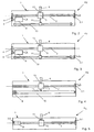
- Figur 1 eine schematisch dargestellte perspektivische Ansicht einer Vorrichtung zum Steuern eines Triebwerkes;
- Figur 2 eine schematisch dargestellte Draufsicht auf eine weitere Vorrichtung zum Steuern eines Triebwerkes;
- Figur 3 eine schematisch dargestellte Draufsicht auf ein weiteres Ausführungsbeispiel der Vorrichtung zum Steuern eines Triebwerkes gemäss den Figuren 1 und 2;
- Figur 4 eine schematisch dargestellte Draufsicht auf ein weiteres Ausführungsbeispiel der Vorrichtung gemäss den Figuren 1 bis 3;
- Figur 5 eine schematisch dargestellte Draufsicht auf ein weiteres Ausführungsbeispiel der Vorrichtung gemäss den Figuren 1 bis 4.
- Gemäss Figur 1 weist eine erfindungsgemässe Vorrichtung R1 zum Steuern eines hier nicht dargestellten Triebwerkes, insbesondere eines Flugzeuges ein Gehäuse 1 auf, in welchem vorzugsweise in seiner Längsrichtung eine Spindel 2 drehbar gelagert ist. Einends sitzt an der Spindel 2 ein Wegmesssystem 3.1 und andernends eine Antriebsscheibe 4.
- Auf der Spindel 2 sitzt eine Führungsbuchse 5, die mit der Spindel 2 im Eingriff steht.
- An die Führungsbuchse 5 schliesst ein Gashebel 6 an. Dieser ist in einem Führungsschlitz 7 das Gehäuse 1 linear geführt. Bevorzugt ist der Führungsschlitz 7 in etwa parallel zur Spindel 2 im Gehäuse 1 der Vorrichtung R1 angeordnet.
- An die Antriebsscheibe 4 schliesst über ein Antriebsrad 8 ein Regelungsmotor 9 einer Regelunseinrichtung an, welcher eine Drehbewegung auf die Spindel 2 überträgt. Durch die Drehbewegung der Spindel 2 wird der Gashebel 6 entlang des Führungsschlitzes 7 linear hin und her bewegt.
- Dem Regelungsmotor 9 bzw. der Regelungseinrichtung ist ein weiteres Wegmesssystem 3.2 zugeordnet, welches über hier nicht bezifferte Verbindungsleitungen mit einer Steuerung 14 in Verbindung steht.
- Auf diese Weise lässt sich über die Stellung der Regelungseinrichtung bzw. des Regelungsmotors 9 exakt ein Rückschluss auf die tatsächliche Stellung und des tatsächlichen Betriebszustandes des Triebwerkes schliessen.
- Zur Unterstützung der Antriebsbewegung der Spindel 2 und insbesondere der linearen Bewegung bei manueller Betätigung des Gashebels 6 ist dem Gashebel 6 und/oder der Führungsbuchse 5 ein Kraftsensor 13 zugeordnet.
- Wird der Gashebel 6 entsprechend, wie in Doppelpfeilrichtung dargestellt mit einer Kraft F bewegt, so wird die Regelungseinrichtung 9 zugeschaltet und betätigt die Spindel 2, damit eine Bewegung und eine automatisch geführtes Bewegen des Gashebels 6 möglich ist.
- Der Pilot muss keinesfalls manuell mit eigener Kraft die Spindel 2 in entsprechende Drehung zu versetzen, um ein Betriebszustand eines anschliessenden Triebwerkes zu verändern.
- Die Funktionswiese der vorliegenden Erfindung ist folgende:
- Wird bspw. mittels eines Autopiloten ein Flugzeug betrieben, so wird mittels des Regelungsmotors 9 der Gashebel 6 entsprechend der Steuerung des Flugzeuges mitbewegt, so dass der Pilot in jeder Lage den Betriebszustand eines Triebwerkes anhand der Position des Gashebels 6 im Führungsschlitz 7 erkennt.
- Gleichzeitig wird bei einem manuellen Betrieb entweder über den Regelungsmotor 9 und/oder über das Wegmesssystem 3.1, 3.2 ein Betriebszustand an einen hier nicht dargestellten Rechner des Flugzeuges übermittelt, welcher dann das entsprechende Triebwerk steuert.
- Insbesondere ist von Vorteil bei der vorliegenden Erfindung, dass manuell der Gashebel 6 bspw. bei einem Ausfall des Regelungsmotors 9 betätigt werden kann und dass der Pilot auf Grund der spindelgelagerten Position des Gashebels 6 erkennt, in welchem Betriebszustand sich das Triebwerk befindet.
- Er kann manuell rein mechanisch den Gashebel 6 verschieben, wodurch sich die Spindel 2 verdreht. Diese Drehbewegung wird im Wegmesssystem 3.1, 3.2 ermittelt und an den entsprechenden Rechner zur Steuerung des Triebwerkes weitergeleitet.
- Daher ist auch bspw. bei einem Energieausfall eine Übermittlung des elektrischen Signales vom Wegmesssystem 3.1, 3.2 zum Triebwerk noch möglich. Dies ist bei der vorliegenden Erfindung von elementarer Bedeutung, da die Sicherheit des Flugzeuges mit einer entsprechenden Vorrichtung zum Betreiben eines Triebwerkes erheblich erhöht wird.
- Bei einem elektrischen Ausfall des Systemes findet keine Selbsthemmung statt. Der Gashebel 6 kann manuell von Hand bewegt werden, wobei die ursprüngliche Position und Stellung des Betriebszustandes des Triebwerkes in jeder Lage ersichtlich ist.
- Eine Selbsthemmung ist deshalb ausgeschlossen, da die Spindel 2 als eine Trapez-Gewinde-Spindel mit einer hohen Steigung ausgebildet ist. Diese weist ferner eine hohe Steifigkeit, insbesondere auch Biege- und Torsionssteifigkeit auf. Sie lässt keine Torosionsbiegungen sowie Kippmomente zu. Daher kann sie sehr präzise durch die lineare Bewegung des Gashebels 6 über die Führungsbuchse 5 ohne jeglicher Gefahr der Selbsthemmung manuell verdreht werden, um den Wegmesssystemen 3.1, 3.2 direkt oder indirekt durch eine manuelle Bewegung das elektrische Signal zur Steuerung des Triebwerkes übermitteln.
- Die Steuerung 14 übernimmt zumindest teilweise die geführte Bewegung des Gashebels 6 bzw. der Führungsbuchse 5, wenn bspw. der Kraftsensor 13 betätigt ist. Dann schaltet entsprechend der Regelungsmotor 9 hinzu, um die manuelle Bewegung des Gashebels 6 elektrisch zu unterstützen. Die Steuerung 14 kann externer Bestandteil des Gehäuses 1 bzw. der Regelungseinrichtung 9 sein. Dies soll vom vorliegenden Erfindungsgedanken umfasst sein.
- In dem Ausführungsbeispiel der vorliegenden Erfindung gemäss Figur 2 ist eine Vorrichtung R2 aufgezeigt, bei welcher in o. b. Weise im Gehäuse 1 die Spindel 2 drehbar gelagert angeordnet ist, wobei einends das Wegmesssytem 3.1, 3.2 zur Messung der Drehungen der Spindel 2 und andernends die Antriebsscheibe 4 angeordnet sind. Die Antriebsscheibe 4 wird über das Antriebsrad 8 mittels des Regelungsmotores 9 mit Wegmesssystem 3.2, in o. b. Weise bspw. beim Betrieb mittels des Autopilotens gesteuert. Dem Gashebel 6 und/oder der Führungsbuchse 5 ist der Kraftsensor 13 zugeordnet, welcher wie oben beschrieben, mit der Steuerung 14 in Verbindung steht.
- Unterschiedlich zu dem Ausführungsbeispiel gemäss Figur 1 ist, dass ein Führungsschlitz 7 entfallen kann, wobei eine lineare Führung über ein lineares Führungselement 10 möglich ist, wenn die Führungsbuchse 5 oder der Gashebel 6 mit dem Führungselement 10 bspw. über ein Verbindungsglied 11 gekoppelt sind. Dabei verläuft das Führungselement 10 in etwa parallel zur Spindel 2.
- Gemäss Figur 3 weist eine Vorrichtung R3 ein Gehäuse 1 auf, in welchem, wie o. b., eine Spindel 2 drehbar gelagert ist. Endseits ist an der Spindel 2 die Antriebsscheibe 4 angeordnet, die über das Antriebsrad 8 des Regelungsmotors 9 mit Wegmesssystem 3.2 drehbar ist. Der Gashebel 6 sitzt mit seiner Führungsbuchse 5 auf der Spindel 2, wobei die Führungsbuchse 5 mit der Spindel 2 im Eingriff steht.
- An die Führungsbuchse 5 oder den Gashebel 6 schliesst sich das Verbindungsglied 11 an und sitzt über eine weitere hier nicht bezifferte Führungsbuchse auf einer als Führungselement 10 ausgebildeten Spindel 2, an deren Ende das Wegmesssystem 3.1 vorgesehen ist.
- Dabei wird das Führungselement 10 beim linearen Bewegen des Gashebels 6 entsprechend verdreht, so dass diese Drehbewegung im Wegmesssystem 3.1, 3.2 ermittelt wird und ein elektrisches Signal direkt oder indirekt an das Triebwerk weiterleitet. Dabei soll im Rahmen der vorliegenden Erfindung liegen, dass auch das Wegmessystem 3.1 entlang des Führungselementes 10 bspw. als Magnetstreifenelement od dgl. ausgebildet sein kann, um beim entsprechenden linearen Verschieben bzw. Bewegen des Gashebels 6 ein Signal entsprechend an das Triebwerk oder an den Rechner des Triebwerkes weiterzuleiten.
- In dem Ausführungsbeispiel der vorliegenden Erfindung gemäss Figur 4 ist eine Vorrichtung R4 aufgezeigt, die im Wesentlichen im Aufbau gemäss Figur 3 entspricht. Unterschiedlich ist, dass der Regelungsmotor 9 ein Antriebsmittel 12 betreibt, welches über das Verbindungsglied 11 mit der Führungsbuchse 5 des Gashebels 6 im Eingriff steht.
- Hierdurch lässt sich automatisch bspw. im Betrieb mittels des Autopiloten der Gashebel 6 entsprechend des Betriebszustandes des Triebwerkes steuern. Dabei kann das Antriebsmittel 12 eine Kette ein Zahnriemen od. dgl. Element sein. Der Erfindung sei hier keine Grenze gesetzt.
- Gemäss Figur 5 ist eine Vorrichtung R5 aufgezeigt, bei welcher in einem Gehäuse 1 entsprechend in oben beschriebener Weise auf der Spindel 2 die Führungsbuchse 5 linear mittels des Gashebels 6 geführt ist. Dem Gashebel 6 und/oder der Führungsbuchse 5 ist der Kraftsensor 13 zugeordnet, welcher ebenfalls mit der nicht dargestellten Steuerung 14 in Verbindung steht.
- Hier schliesst direkt die Regelungseinrichtung 9, insbesondere der Regelungsmotor an die Spindel 2 an. Ggf. ist wie gestrichelt angedeutet, ein Getriebe vorgeschaltet.
- Andernends sitzt auf der Spindel 2 in oben beschriebener Weise das Wegmesssystem 3.1. Ferner ist der Regelungseinrichtung 9 ebenfalls, wie oben beschrieben, das Wegmesssystem 3.2 zugeordnet. Der Gashebel 6 wird im Gehäuse 1 entsprechend Figur 1 linear geführt.
Positionszahlenliste 1 Gehäuse 34 67 2 Spindel 35 68 3 Wegmesssystem 36 69 4 Antriebsscheibe 37 70 5 Führungsbuchse 38 71 6 Gashebel 39 72 7 Führungsschlitz 40 73 8 Antriebsrad 41 74 9 Regelungseinrichtung 42 75 10 Führungselement 43 76 11 Verbindungsglied 44 77 12 Antriebsmittel 45 78 13 Kraftsensor 46 79 14 Steuerung 47 15 48 16 49 R1 Vorrichtung 17 50 R2 Vorrichtung 18 51 R3 Vorrichtung 19 52 R4 Vorrichtung 20 53 R5 Vorrichtung 21 54 22 55 F Kraft 23 56 24 57 25 58 26 59 27 60 28 61 29 62 30 63 31 64 32 65 33 66
Claims (9)
- Vorrichtung zum Steuern eines Triebwerkes, insbesondere eines Flugzeuges mit zumindest einem Gashebel (6) und einer Regelungseinrichtung (9) zum zusätzlichen automatischen Antreiben des Gashebels (6), wobei eine Bewegung des Gashebels (6) permanent, direkt oder indirekt auf ein Wegmesssystem (3.1, 3.2) übertragbar und der Gashebel (6) über eine Führungsbuchse (5) einer drehbaren Spindel (2) linear bewegbar gelagert aufsitzt, wobei die Spindel (2) als nicht selbsthemmende Spindel (2) mit hoher Steigung ausgebildet ist, und eine lineare, manuelle Bewegung des Gashebels (6) auf das Wegmesssystem (3.1, 3.2) mechanisch übertragbar ist, und eine lineare, mechanische und automatische Bewegung des Gashebels (6) mechanisch an die Bewegung des Wegmesssystems (3.1, 3.2) gekoppelt ist, und der Gashebel (6) linear in einem Führungsschlitz (7) eines Gehäuses (1) geführt ist, welcher in etwa parallel zur Spindel (2) angeordnet ist,
dadurch gekennzeichnet,
dass zur Unterstützung einer manuellen, linearen Bewegung des Gashebels (6) die Regelungseinrichtung (9) auf ein Signal eines Kraftsensors (13) einschaltbar ist und der Kraftsensor (13) dem Gashebel (6) und/oder der Führungsbuchse (5) zugeordnet ist. - Vorrichtung nach Anspruch 1, dadurch gekennzeichnet, dass durch eine lineare Bewegung des Gashebels (6) die Spindel (2) entsprechend der Bewegung der Führungsbuchse (5) drehbar gelagert ist.
- vorrichtung nach Anspruch 1 oder 2, dadurch gekennzeichnet, dass einends an der Spindel (2) das Wegmesssystem (3.1) angeordnet ist.
- Vorrichtung nach wenigstens einem der Ansprüche 1 bis 3, dadurch gekennzeichnet, dass andernends der Spindel (2) die Regelungseinrichtung (9) als Regelungsmotor mit ggf. einem zugeordneten Wegmesssystem (3.2) direkt oder indirekt angreift.
- Vorrichtung nach wenigstens einem der Ansprüche 1 bis 4, dadurch gekennzeichnet, dass einends an der Spindel (2) eine Antriebsscheibe (4) angeordnet ist.
- Vorrichtung nach Anspruch 5, dadurch gekennzeichnet, dass der Regelungsmotor (9) mit der Antriebsscheibe (4) in Verbindung steht.
- Vorrichtung nach wenigstens einem der Ansprüche 1 bis 6, dadurch gekennzeichnet, dass der Gashebel (6) direkt oder indirekt mit einem Führungselement (10) verbunden ist, welches in etwa parallel zur Spindel (2) verläuft.
- Vorrichtung nach wenigstens einem der Ansprüche 1 bis 7, dadurch gekennzeichnet, dass das Wegmesssystem (3.1, 3.2) als Wegaufnehmer von induktiver, magnetischer oder optischer Art ist.
- Vorrichtung nach wenigstens einem der Ansprüche 1 bis 8, dadurch gekennzeichnet, dass das Wegmesssystem (3.1, 3.2) und/oder der Kraftsensor (13) und/oder die Regelungseinrichtung (9) mit einer Steuerung (14) in Verbindung steht, um eine manuelle Bewegung des Gashebels (6) durch Hinzuschalten der Regelungseinrichtung (9) zu unterstützen, wobei die jeweiligen Positionen des Gashebels (6) entsprechend des Betriebszustandes über die Wegmesssysteme (3.1, 3.2) an ein Triebwerk weiterleitbar sind.
Applications Claiming Priority (3)
| Application Number | Priority Date | Filing Date | Title |
|---|---|---|---|
| DE19926800 | 1999-06-11 | ||
| DE19926800A DE19926800A1 (de) | 1999-06-11 | 1999-06-11 | Vorrichtung zum Steuern eines Triebwerkes |
| PCT/EP2000/005133 WO2000076842A1 (de) | 1999-06-11 | 2000-06-06 | Vorrichtung zum steuern eines triebwerkes |
Publications (2)
| Publication Number | Publication Date |
|---|---|
| EP1185454A1 EP1185454A1 (de) | 2002-03-13 |
| EP1185454B1 true EP1185454B1 (de) | 2006-03-29 |
Family
ID=7911010
Family Applications (1)
| Application Number | Title | Priority Date | Filing Date |
|---|---|---|---|
| EP00938756A Expired - Lifetime EP1185454B1 (de) | 1999-06-11 | 2000-06-06 | Vorrichtung zum steuern eines triebwerkes |
Country Status (4)
| Country | Link |
|---|---|
| US (1) | US6973915B1 (de) |
| EP (1) | EP1185454B1 (de) |
| DE (2) | DE19926800A1 (de) |
| WO (1) | WO2000076842A1 (de) |
Cited By (2)
| Publication number | Priority date | Publication date | Assignee | Title |
|---|---|---|---|---|
| EP4644253A1 (de) * | 2024-05-03 | 2025-11-05 | BAE SYSTEMS plc | Aktive lineare drosselanordnung |
| WO2025229343A1 (en) * | 2024-05-03 | 2025-11-06 | Bae Systems Plc | Active linear throttle assembly |
Families Citing this family (11)
| Publication number | Priority date | Publication date | Assignee | Title |
|---|---|---|---|---|
| DE10310717A1 (de) | 2003-03-10 | 2004-09-23 | Wittenstein Ag | Vorrichtung zum Steuern eines Fahrzeuges |
| US10099795B2 (en) * | 2015-11-04 | 2018-10-16 | Innovative Solutions & Support, Inc. | Precision operator for an aircraft autothrottle or autopilot system |
| US10737799B2 (en) | 2015-11-04 | 2020-08-11 | Geoffrey S. M. Hedrick | Precision operator for an aircraft autothrottle or autopilot system with engine performance adjust |
| CN105416598B (zh) * | 2015-12-04 | 2017-04-26 | 贵州华阳电工有限公司 | 油门台操纵机构 |
| US10604268B2 (en) * | 2017-02-22 | 2020-03-31 | Pratt & Whitney Canada Corp. | Autothrottle control for turboprop engines |
| FR3068733B1 (fr) | 2017-07-05 | 2019-08-09 | Fly By Wire Systems France | Systeme de commande de gaz d'un aeronef |
| US11479364B2 (en) * | 2017-12-13 | 2022-10-25 | Safe Flight Instrument, Llc | Aircraft torque control device |
| EP4154098A4 (de) | 2020-06-26 | 2024-05-15 | Innovative Solutions & Support, Inc. | Flugzeugsteuerung für ausdauer und kraftstoffeinsparung |
| GB2640730A (en) * | 2024-05-03 | 2025-11-05 | Bae Systems Plc | Active throttle assembly |
| EP4644235A1 (de) * | 2024-05-03 | 2025-11-05 | BAE SYSTEMS plc | Aktive drosselanordnung |
| WO2025229344A1 (en) * | 2024-05-03 | 2025-11-06 | Bae Systems Plc | Active throttle assembly |
Citations (1)
| Publication number | Priority date | Publication date | Assignee | Title |
|---|---|---|---|---|
| EP0875451A2 (de) * | 1997-03-27 | 1998-11-04 | British Aerospace Public Limited Company | Elektronisches Flugzeugleistungskontrollhebelsystem |
Family Cites Families (8)
| Publication number | Priority date | Publication date | Assignee | Title |
|---|---|---|---|---|
| GB2073887B (en) * | 1980-03-15 | 1984-04-26 | British Aerospace | Aircraft thrust controller |
| GB2114717B (en) * | 1982-01-22 | 1986-03-12 | British Aerospace | Control apparatus |
| US4665765A (en) * | 1985-04-30 | 1987-05-19 | Heine Otto R | Anti-friction worm gear speed reducer and needle screw |
| US4643148A (en) * | 1985-09-16 | 1987-02-17 | Avco Corporation | Mechanical override for electronic fuel control on a piston engine |
| US5740884A (en) * | 1993-08-09 | 1998-04-21 | Dimucci; Vito A. | Power lifting unit and method for converting mobile patient transporter |
| US5489830A (en) * | 1994-09-09 | 1996-02-06 | Mcdonnell Douglas Corporation | Control system with loadfeel and backdrive |
| JP3221804B2 (ja) * | 1994-09-28 | 2001-10-22 | 先生精機株式会社 | アクチュエータ |
| FR2728537A1 (fr) * | 1994-12-21 | 1996-06-28 | Eurocopter France | Dispositif pour l'actionnement d'un organe commande pour un aeronef, tel que notamment un helicoptere, a commandes de vol electriques |
-
1999
- 1999-06-11 DE DE19926800A patent/DE19926800A1/de not_active Withdrawn
-
2000
- 2000-06-06 US US10/009,006 patent/US6973915B1/en not_active Expired - Lifetime
- 2000-06-06 EP EP00938756A patent/EP1185454B1/de not_active Expired - Lifetime
- 2000-06-06 WO PCT/EP2000/005133 patent/WO2000076842A1/de not_active Ceased
- 2000-06-06 DE DE50012486T patent/DE50012486D1/de not_active Expired - Lifetime
Patent Citations (1)
| Publication number | Priority date | Publication date | Assignee | Title |
|---|---|---|---|---|
| EP0875451A2 (de) * | 1997-03-27 | 1998-11-04 | British Aerospace Public Limited Company | Elektronisches Flugzeugleistungskontrollhebelsystem |
Cited By (2)
| Publication number | Priority date | Publication date | Assignee | Title |
|---|---|---|---|---|
| EP4644253A1 (de) * | 2024-05-03 | 2025-11-05 | BAE SYSTEMS plc | Aktive lineare drosselanordnung |
| WO2025229343A1 (en) * | 2024-05-03 | 2025-11-06 | Bae Systems Plc | Active linear throttle assembly |
Also Published As
| Publication number | Publication date |
|---|---|
| DE19926800A1 (de) | 2000-12-14 |
| WO2000076842A1 (de) | 2000-12-21 |
| US6973915B1 (en) | 2005-12-13 |
| EP1185454A1 (de) | 2002-03-13 |
| DE50012486D1 (de) | 2006-05-18 |
Similar Documents
| Publication | Publication Date | Title |
|---|---|---|
| EP1185454B1 (de) | Vorrichtung zum steuern eines triebwerkes | |
| EP1929112B1 (de) | Möbelscharnier | |
| DE69703635T2 (de) | Angetriebene Verriegelungsvorrichtung für Fahrzeuge mit verbesserten Mitteln zur Begrenzung der Bewegung eines Riegels | |
| EP0447626A2 (de) | Aktuator für eine kybernetisce Lenkung | |
| EP1371802A2 (de) | Kraftfahrzeug-Türverschluss mit einem elektromechanischen Zentralverriegelungsantrieb | |
| DE3927043A1 (de) | Lastverstelleinrichtung | |
| EP1358099B1 (de) | Aktuator für eine steer-by-wire-lenkanlage | |
| EP2964508B1 (de) | Begrenzungseinrichtung für die lenkwinkeleingabe in einer elektrischen lenkung | |
| DE69214209T2 (de) | Hinterradlenkapparat für Radfahrzeug | |
| EP0969998B1 (de) | Kraftfahrzeug mit zumindest einem über wenigstens einen bedienhebel steuerbaren teil | |
| DE1463495A1 (de) | Endlagensteuereinheit | |
| EP0402521B1 (de) | Lastverstelleinrichtung | |
| WO2000027686A1 (de) | Ventilanordnung für servolenkungen | |
| EP1167822B1 (de) | Einrichtung zur Erzeugung einer Längsbewegung und/oder einer Drehbewegung | |
| DE3728008A1 (de) | Betaetigungseinrichtung fuer bewegbare teile zum wahlweisen schliessen und freigeben von oeffnungen, insbesondere von schiebe-hebedaechern von kraftfahrzeugen | |
| DE1155950B (de) | Elektromotorischer Antrieb fuer Ventile, Schieber od. dgl. | |
| EP1185455B1 (de) | Vorrichtung zum steuern eines triebwerkes | |
| EP0699552B1 (de) | Vorrichtung zur Handbetätigung des Leistungsreglers eines Kraftfahrzeuges | |
| WO2013037562A1 (de) | Schalteinheit mit spindeltrieb für ein werkzeugmaschinengetriebe | |
| DE2942793C2 (de) | Elektromotorisch angetriebene Verstelleinrichtung | |
| DE3442894A1 (de) | Stelleinrichtung, insbesondere zum verriegeln und entriegeln von kraftfahrzeugtueren | |
| EP0257538B1 (de) | Schaltanordnung in Kraftfahrzeugen | |
| DE3327946C2 (de) | ||
| DE2700928A1 (de) | Stellantrieb fuer luft- und drosselklappen, mischhaehne u.dgl. in heizungs- und lueftungsanlagen | |
| DE3632902A1 (de) | Steuereinrichtung fuer motorische verstellung von fahrzeugsitzen |
Legal Events
| Date | Code | Title | Description |
|---|---|---|---|
| PUAI | Public reference made under article 153(3) epc to a published international application that has entered the european phase |
Free format text: ORIGINAL CODE: 0009012 |
|
| 17P | Request for examination filed |
Effective date: 20011108 |
|
| AK | Designated contracting states |
Kind code of ref document: A1 Designated state(s): AT BE CH CY DE DK ES FI FR GB GR IE IT LI LU MC NL PT SE |
|
| RAP1 | Party data changed (applicant data changed or rights of an application transferred) |
Owner name: WITTENSTEIN AG |
|
| 17Q | First examination report despatched |
Effective date: 20030606 |
|
| RBV | Designated contracting states (corrected) |
Designated state(s): DE FR GB IT |
|
| GRAP | Despatch of communication of intention to grant a patent |
Free format text: ORIGINAL CODE: EPIDOSNIGR1 |
|
| GRAS | Grant fee paid |
Free format text: ORIGINAL CODE: EPIDOSNIGR3 |
|
| GRAA | (expected) grant |
Free format text: ORIGINAL CODE: 0009210 |
|
| AK | Designated contracting states |
Kind code of ref document: B1 Designated state(s): DE FR GB IT |
|
| PG25 | Lapsed in a contracting state [announced via postgrant information from national office to epo] |
Ref country code: IT Free format text: LAPSE BECAUSE OF FAILURE TO SUBMIT A TRANSLATION OF THE DESCRIPTION OR TO PAY THE FEE WITHIN THE PRESCRIBED TIME-LIMIT;WARNING: LAPSES OF ITALIAN PATENTS WITH EFFECTIVE DATE BEFORE 2007 MAY HAVE OCCURRED AT ANY TIME BEFORE 2007. THE CORRECT EFFECTIVE DATE MAY BE DIFFERENT FROM THE ONE RECORDED. Effective date: 20060329 |
|
| REG | Reference to a national code |
Ref country code: GB Ref legal event code: FG4D Free format text: NOT ENGLISH |
|
| GBT | Gb: translation of ep patent filed (gb section 77(6)(a)/1977) |
Effective date: 20060329 |
|
| REF | Corresponds to: |
Ref document number: 50012486 Country of ref document: DE Date of ref document: 20060518 Kind code of ref document: P |
|
| ET | Fr: translation filed | ||
| PLBE | No opposition filed within time limit |
Free format text: ORIGINAL CODE: 0009261 |
|
| STAA | Information on the status of an ep patent application or granted ep patent |
Free format text: STATUS: NO OPPOSITION FILED WITHIN TIME LIMIT |
|
| 26N | No opposition filed |
Effective date: 20070102 |
|
| PGFP | Annual fee paid to national office [announced via postgrant information from national office to epo] |
Ref country code: FR Payment date: 20140619 Year of fee payment: 15 |
|
| REG | Reference to a national code |
Ref country code: DE Ref legal event code: R082 Ref document number: 50012486 Country of ref document: DE Representative=s name: PATENTANWAELTE UND RECHTSANWALT DR. WEISS, ARA, DE Ref country code: DE Ref legal event code: R082 Ref document number: 50012486 Country of ref document: DE Representative=s name: PATENTANWAELTE UND RECHTSANWALT WEISS, ARAT & , DE |
|
| REG | Reference to a national code |
Ref country code: FR Ref legal event code: ST Effective date: 20160229 |
|
| PG25 | Lapsed in a contracting state [announced via postgrant information from national office to epo] |
Ref country code: FR Free format text: LAPSE BECAUSE OF NON-PAYMENT OF DUE FEES Effective date: 20150630 |
|
| REG | Reference to a national code |
Ref country code: DE Ref legal event code: R082 Ref document number: 50012486 Country of ref document: DE Representative=s name: PATENTANWAELTE UND RECHTSANWALT WEISS, ARAT & , DE Ref country code: DE Ref legal event code: R081 Ref document number: 50012486 Country of ref document: DE Owner name: WITTENSTEIN SE, DE Free format text: FORMER OWNER: WITTENSTEIN AG, 97999 IGERSHEIM, DE |
|
| PGFP | Annual fee paid to national office [announced via postgrant information from national office to epo] |
Ref country code: GB Payment date: 20170620 Year of fee payment: 18 |
|
| PGFP | Annual fee paid to national office [announced via postgrant information from national office to epo] |
Ref country code: DE Payment date: 20170829 Year of fee payment: 18 |
|
| REG | Reference to a national code |
Ref country code: DE Ref legal event code: R119 Ref document number: 50012486 Country of ref document: DE |
|
| GBPC | Gb: european patent ceased through non-payment of renewal fee |
Effective date: 20180606 |
|
| PG25 | Lapsed in a contracting state [announced via postgrant information from national office to epo] |
Ref country code: GB Free format text: LAPSE BECAUSE OF NON-PAYMENT OF DUE FEES Effective date: 20180606 Ref country code: DE Free format text: LAPSE BECAUSE OF NON-PAYMENT OF DUE FEES Effective date: 20190101 |