EP1185454B1 - Dispositif pour commander un groupe moteur - Google Patents
Dispositif pour commander un groupe moteur Download PDFInfo
- Publication number
- EP1185454B1 EP1185454B1 EP00938756A EP00938756A EP1185454B1 EP 1185454 B1 EP1185454 B1 EP 1185454B1 EP 00938756 A EP00938756 A EP 00938756A EP 00938756 A EP00938756 A EP 00938756A EP 1185454 B1 EP1185454 B1 EP 1185454B1
- Authority
- EP
- European Patent Office
- Prior art keywords
- throttle lever
- spindle
- movement
- measuring system
- range measuring
- Prior art date
- Legal status (The legal status is an assumption and is not a legal conclusion. Google has not performed a legal analysis and makes no representation as to the accuracy of the status listed.)
- Expired - Lifetime
Links
Images

Classifications
-
- B—PERFORMING OPERATIONS; TRANSPORTING
- B64—AIRCRAFT; AVIATION; COSMONAUTICS
- B64D—EQUIPMENT FOR FITTING IN OR TO AIRCRAFT; FLIGHT SUITS; PARACHUTES; ARRANGEMENTS OR MOUNTING OF POWER PLANTS OR PROPULSION TRANSMISSIONS IN AIRCRAFT
- B64D31/00—Power plant control; Arrangement thereof
- B64D31/02—Initiating means
- B64D31/04—Initiating means actuated personally
Definitions
- the present invention relates to a device for controlling an engine, in particular an aircraft with at least one throttle lever and a control device for additional automatic driving of the throttle lever, wherein a movement of the throttle lever permanently, directly or indirectly transferable to a displacement measuring system and the throttle lever via a guide bushing of a rotatable Spindle linearly movably mounted.
- Such devices are known in many forms and designs on the market and in use. They serve in particular for controlling and starting up an engine, for example an aircraft.
- a disadvantage of such conventional devices is that they do not provide sufficient security, if, for example. In Operation with an autopilot the circuit or even the control motor fails.
- GB 2 114 717 A discloses a control device for actively driving, for example, a throttle lever for controlling aircraft engines.
- the throttle lever is in engagement with a spindle, which has a low pitch and is designed to be self-locking.
- the throttle can only be activated actively by a drive motor which is directly or indirectly connected to the spindle.
- the disadvantage of this is that, in the event of a power failure, the spindle, in particular the throttle lever, can not be moved or driven manually.
- US 4,494,061 describes a control device for an aircraft, wherein a throttle lever is actively moved via motors to indicate the current operating state of an engine.
- EP 0 875 451 A2 discloses an electronic control device for aircraft in which a handle is actively reciprocable by means of two servomotors.
- the present invention has for its object to provide a device of the type mentioned in which a simple, safe and cost-effective way Control and control of an engine permanently manually and / or automatically possible.
- the spindle is designed as a non-self-locking spindle with high pitch and to support a manual, linear movement of the throttle lever
- the control device is switched to a signal of a force sensor, and a linear, manual movement of the throttle lever on a position measuring system mechanically is transferable, wherein a linear, mechanical and automatic movement of the throttle lever is mechanically coupled to the movement of a Wegemesssystems and the energy storage is associated with the throttle and / or the guide bush, wherein the throttle is linearly guided in a guide slot of a housing, which is approximately parallel is arranged to the spindle.
- the throttle lever is seated on a spindle which is drivable via a control motor for operation by means of autopilot. Then the pilot recognizes the current state, in particular the operating state of the engine, in every position and situation.
- this control motor can manually actuate the throttle.
- a spindle rotates, at the end of which a position measuring system is seated.
- This displacement measuring system then transmits the corresponding information directly or indirectly via a computer to the engine. Then the movement of the throttle lever is independent of the control motor.
- Wegmesssysteme for example. Are suitable to detect a rotational movement or a linear movement of the throttle lever and convert it into a signal.
- the displacement measuring system can be inductive, magnetic and / or optical type.
- the invention no limit set.
- the throttle lever is guided linearly in a guide slot or along a guide member to produce by means of the guide bush, which is in engagement with the spindle, a rotational movement with the spindle. This rotational movement of the spindle is then transmitted to the position measuring system.
- a spindle as a trapezoidal threaded spindle having a high pitch. This ensures absolute security against self-locking during manual and / or electrical movement of the guide bush, in particular of the throttle lever in the guide slot. Furthermore, such trapezoidal threaded spindles have high stiffness, and no tilting moments. These are suitable for linear precision lead. In addition, a complex design is guaranteed in a very small space and is very inexpensive to manufacture.
- the spindle is set in rotation, said rotation of the spindle is transmitted directly to the position measuring system. This then provides the appropriate signals to control the engine.
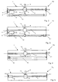
- an apparatus R 1 for controlling an engine, not shown here, in particular an aircraft, has a housing 1 in which a spindle 2 is preferably rotatably mounted in its longitudinal direction. At one end sits on the spindle 2, a displacement measuring system 3.1 and the other end a drive pulley. 4
- a throttle lever 6 connects. This is in a guide slot 7, the housing 1 linear guided.
- the guide slot 7 is arranged approximately parallel to the spindle 2 in the housing 1 of the device R 1 .
- the control motor 9 and the control device is assigned a further displacement measuring system 3.2, which communicates with a controller 14 via connecting lines not numbered here.
- the position of the regulating device or the regulating motor 9 allows a precise conclusion to be drawn about the actual position and the actual operating state of the engine.
- a force sensor 13 is associated.
- the control device 9 is switched on and actuates the spindle 2, so that a movement and an automatically guided movement of the throttle lever 6 is possible.
- the pilot must by no means manually with their own power to put the spindle 2 in corresponding rotation to change an operating state of a subsequent engine.
- the throttle lever 6 is moved in accordance with the control of the aircraft by means of the control motor 9, so that the pilot recognizes the operating state of an engine in each position based on the position of the throttle lever 6 in the guide slot 7.
- manually the throttle 6 can be actuated, for example, in the event of failure of the control motor 9 and that the pilot recognizes due to the spindle-mounted position of the throttle lever 6, in which operating state is the engine.
- the throttle 6 can be moved manually by hand, the original position and position of the operating condition of the engine is visible in each position.
- the spindle 2 is formed as a trapezoidal threaded spindle with a high pitch.
- This also has a high rigidity, in particular also bending and torsional rigidity. It allows no Torosionsbiegonne and tilting moments. Therefore, it can be rotated very precisely by the linear movement of the throttle lever 6 via the guide bushing 5 without any risk of self-locking to the Wegmesssystemen 3.1, 3.2 transmit directly or indirectly by manual movement of the electrical signal to control the engine.
- the controller 14 takes over at least partially the guided movement of the throttle lever 6 and the guide bushing 5, when, for example, the force sensor 13 is actuated. Then, according to the control motor 9 is added to assist the manual movement of the throttle lever 6 electrically.
- the controller 14 may be an external component of the housing 1 or the control device 9. This is intended to be encompassed by the present inventive concept.
- a device R 2 is shown in which in which way in the housing 1, the spindle 2 is rotatably mounted, wherein at one end the Wegmesssytem 3.1, 3.2 for measuring the rotations of the spindle 2 and the other hand, the drive pulley 4 are arranged.
- the drive pulley 4 is controlled via the drive wheel 8 by means of the control motor 9 with position measuring system 3.2, in the same way, for example, when operating by means of autopilot.
- the throttle lever 6 and / or the guide bush 5 is associated with the force sensor 13, which, as described above, is in communication with the controller 14.
- a guide slot 7 can be dispensed with, wherein a linear guide via a linear guide element 10 is possible if the guide bush 5 or the throttle lever 6 are coupled to the guide element 10, for example via a connecting link 11.
- the guide element 10 extends approximately parallel to the spindle. 2
- a device R 3 has a housing 1 in which, as if, a spindle 2 is rotatably mounted.
- the drive pulley 4 is arranged, which is rotatable about the drive wheel 8 of the control motor 9 with position measuring system 3.2.
- the throttle 6 sits with its guide bushing 5 on the spindle 2, wherein the guide bushing 5 is in engagement with the spindle 2.
- the connecting member 11 closes and sits on another not here figured guide bushing on a trained as a guide element 10 spindle 2, at the end of the displacement measuring 3.1 is provided.
- the guide element 10 is correspondingly rotated during the linear movement of the throttle lever 6, so that this rotational movement in the displacement measuring system 3.1, 3.2 is determined and forwards an electrical signal directly or indirectly to the engine.
- the Wegmessystem 3.1 along the guide member 10, for example, as magnetic stripe element or the like. May be designed to forward the corresponding linear displacement or movement of the throttle 6, a signal corresponding to the engine or to the computer of the engine.
- a device R 4 which corresponds essentially to the structure according to FIG. It is different that the control motor 9 operates a drive means 12, which is connected via the connecting member 11 with the guide bush 5 of the throttle lever 6 in engagement.
- the drive means 12 a chain od a toothed belt.
- the invention is not limited here.
- a device R 5 is shown, in which in a housing 1 in accordance with the manner described above on the spindle 2, the guide bushing 5 is guided linearly by means of the throttle lever 6.
- the throttle lever 6 and / or the guide bush 5 is associated with the force sensor 13, which is also in communication with the controller 14, not shown.
- control device 9 in particular the control motor, directly adjoins the spindle 2. Possibly. is as indicated by dashed lines, a transmission upstream.
Claims (9)
- Dispositif pour commander un groupe moteur, en particulier d'un avion, avec au moins un levier à gaz (6) et un dispositif de régulation (9) destiné à l'actionnement automatique additionnel du levier à gaz (6), un mouvement du levier à gaz (6) pouvant être transmis en permanence, directement ou indirectement, à un système de mesure de chemin (3.1, 3.2) et le levier à gaz (6) étant placé monté déplaçable linéairement par l'intermédiaire d'une douille de guidage (5) d'un axe rotatif (2), l'axe étant réalisé sous forme d'axe (2) non autobloquant à grande montée et un mouvement linéaire manuel du levier à gaz (6) pouvant être transmis mécaniquement au système de mesure de chemin (3.1, 3.2) et un mouvement linéaire mécanique et automatique du levier à gaz (6) étant couplé au mouvement du système de mesure de chemin (3.1, 3.2) et le levier à gaz (6) étant guidé linéairement dans une fente de guidage (7) d'un boîtier (1) disposée environ parallèlement à l'axe (2),
caractérisé par le fait
que, pour supporter un mouvement manuel linéaire du levier à gaz (6), le dispositif de régulation (9) peut être enclenché sur un signal d'un capteur de force (13) et que le capteur de force (13) est associé au levier à gaz (6) et/ou à la douille de guidage (5}. - Dispositif selon la revendication 1, caractérisé par le fait que, par un mouvement linéaire du levier à gaz (6), l'axe (2) est monté de manière rotative selon le mouvement de la douille de guidage (5).
- Dispositif selon la revendication 1 ou 2, caractérisé par le fait qu'à une extrémité de l'axe (2) est disposé le système de mesure de chemin (3.1).
- Dispositif selon au moins l'une des revendications 1 à 3, caractérisé par le fait qu'à l'autre extrémité de l'axe (2) vient en prise, directement ou indirectement, le dispositif de régulation (9) sous forme de moteur de régulation avec éventuellement un système de mesure de chemin (3.2) associé.
- Dispositif selon au moins l'une des revendications 1 à 4, caractérisé par le fait qu'à une extrémité de l'axe (2) est disposé un disque d'entraînement (4).
- Dispositif selon la revendication 5, caractérisé par le fait que le moteur de régulation (9) est en communication avec le disque d'entraînement (4).
- Dispositif selon au moins l'une des revendications 1 à 6, caractérisé par le fait que le levier à gaz (6) est relié, directement ou indirectement, à un élément de guidage (10) qui s'étend environ parallèlement à l'axe (2).
- Dispositif selon au moins l'une des revendications 1 à 7, caractérisé par le fait que le système de mesure de chemin (3.1, 3.2) est réalisé sous forme d'enregistreur de chemin de type inductif, magnétique ou optique.
- Dispositif selon au moins l'une des revendications 1 à 8, caractérisé par le fait que le système de mesure de chemin (3.1, 3.2) et/ou le capteur de force (13) et/ou le dispositif de régulation (9) est en communication avec une commande (14), pour supporter un mouvement manuel du levier à gaz (6) par l'addition du dispositif de régulation (9), les positions respectives du levier à gaz (6) pouvant être transmises à un groupe moteur, par l'intermédiaire des systèmes de mesure de chemin (3.1, 3.2), en fonction de l'état de fonctionnement.
Applications Claiming Priority (3)
| Application Number | Priority Date | Filing Date | Title |
|---|---|---|---|
| DE19926800A DE19926800A1 (de) | 1999-06-11 | 1999-06-11 | Vorrichtung zum Steuern eines Triebwerkes |
| DE19926800 | 1999-06-11 | ||
| PCT/EP2000/005133 WO2000076842A1 (fr) | 1999-06-11 | 2000-06-06 | Dispositif pour commander un groupe moteur |
Publications (2)
| Publication Number | Publication Date |
|---|---|
| EP1185454A1 EP1185454A1 (fr) | 2002-03-13 |
| EP1185454B1 true EP1185454B1 (fr) | 2006-03-29 |
Family
ID=7911010
Family Applications (1)
| Application Number | Title | Priority Date | Filing Date |
|---|---|---|---|
| EP00938756A Expired - Lifetime EP1185454B1 (fr) | 1999-06-11 | 2000-06-06 | Dispositif pour commander un groupe moteur |
Country Status (4)
| Country | Link |
|---|---|
| US (1) | US6973915B1 (fr) |
| EP (1) | EP1185454B1 (fr) |
| DE (2) | DE19926800A1 (fr) |
| WO (1) | WO2000076842A1 (fr) |
Families Citing this family (7)
| Publication number | Priority date | Publication date | Assignee | Title |
|---|---|---|---|---|
| DE10310717A1 (de) * | 2003-03-10 | 2004-09-23 | Wittenstein Ag | Vorrichtung zum Steuern eines Fahrzeuges |
| JP6851976B2 (ja) * | 2015-11-04 | 2021-03-31 | ジェフリー エス エム ヘドリック | 航空機のオートスロットル又は自動操縦装置用精密オペレーター |
| US10737799B2 (en) | 2015-11-04 | 2020-08-11 | Geoffrey S. M. Hedrick | Precision operator for an aircraft autothrottle or autopilot system with engine performance adjust |
| CN105416598B (zh) * | 2015-12-04 | 2017-04-26 | 贵州华阳电工有限公司 | 油门台操纵机构 |
| US10604268B2 (en) * | 2017-02-22 | 2020-03-31 | Pratt & Whitney Canada Corp. | Autothrottle control for turboprop engines |
| FR3068733B1 (fr) * | 2017-07-05 | 2019-08-09 | Fly By Wire Systems France | Systeme de commande de gaz d'un aeronef |
| US11479364B2 (en) * | 2017-12-13 | 2022-10-25 | Safe Flight Instrument, Llc | Aircraft torque control device |
Citations (1)
| Publication number | Priority date | Publication date | Assignee | Title |
|---|---|---|---|---|
| EP0875451A2 (fr) * | 1997-03-27 | 1998-11-04 | British Aerospace Public Limited Company | Commande de puissance électronique pour aéronef |
Family Cites Families (8)
| Publication number | Priority date | Publication date | Assignee | Title |
|---|---|---|---|---|
| GB2073887B (en) * | 1980-03-15 | 1984-04-26 | British Aerospace | Aircraft thrust controller |
| GB2114717B (en) * | 1982-01-22 | 1986-03-12 | British Aerospace | Control apparatus |
| US4665765A (en) * | 1985-04-30 | 1987-05-19 | Heine Otto R | Anti-friction worm gear speed reducer and needle screw |
| US4643148A (en) * | 1985-09-16 | 1987-02-17 | Avco Corporation | Mechanical override for electronic fuel control on a piston engine |
| US5740884A (en) * | 1993-08-09 | 1998-04-21 | Dimucci; Vito A. | Power lifting unit and method for converting mobile patient transporter |
| US5489830A (en) * | 1994-09-09 | 1996-02-06 | Mcdonnell Douglas Corporation | Control system with loadfeel and backdrive |
| JP3221804B2 (ja) * | 1994-09-28 | 2001-10-22 | 先生精機株式会社 | アクチュエータ |
| FR2728537A1 (fr) * | 1994-12-21 | 1996-06-28 | Eurocopter France | Dispositif pour l'actionnement d'un organe commande pour un aeronef, tel que notamment un helicoptere, a commandes de vol electriques |
-
1999
- 1999-06-11 DE DE19926800A patent/DE19926800A1/de not_active Withdrawn
-
2000
- 2000-06-06 DE DE50012486T patent/DE50012486D1/de not_active Expired - Lifetime
- 2000-06-06 US US10/009,006 patent/US6973915B1/en not_active Expired - Lifetime
- 2000-06-06 EP EP00938756A patent/EP1185454B1/fr not_active Expired - Lifetime
- 2000-06-06 WO PCT/EP2000/005133 patent/WO2000076842A1/fr active IP Right Grant
Patent Citations (1)
| Publication number | Priority date | Publication date | Assignee | Title |
|---|---|---|---|---|
| EP0875451A2 (fr) * | 1997-03-27 | 1998-11-04 | British Aerospace Public Limited Company | Commande de puissance électronique pour aéronef |
Also Published As
| Publication number | Publication date |
|---|---|
| DE19926800A1 (de) | 2000-12-14 |
| DE50012486D1 (de) | 2006-05-18 |
| US6973915B1 (en) | 2005-12-13 |
| EP1185454A1 (fr) | 2002-03-13 |
| WO2000076842A1 (fr) | 2000-12-21 |
Similar Documents
| Publication | Publication Date | Title |
|---|---|---|
| EP1929112B1 (fr) | Charniere de meuble | |
| EP0447626A2 (fr) | Déclencheur pour une direction cybernétique | |
| EP1371802A2 (fr) | Serrure de porte pour véhicule automobile avec condamnation centrale actionnée électromécaniquement | |
| EP0413082A1 (fr) | Dispositif de réglage de charge | |
| EP1185454B1 (fr) | Dispositif pour commander un groupe moteur | |
| EP2964508B1 (fr) | Dispositif de limitation de l'effort de direction dans une direction assistée électrique | |
| EP1358099B1 (fr) | Actionneur pour systeme de direction a commande par cable | |
| DE1463495A1 (de) | Endlagensteuereinheit | |
| EP0402521B1 (fr) | Dispositif de réglage de charge | |
| EP0969998B1 (fr) | Automobile comportant au moins une partie pouvant etre pilotee par l'intermediaire d'au moins un levier de commande | |
| DE3728008A1 (de) | Betaetigungseinrichtung fuer bewegbare teile zum wahlweisen schliessen und freigeben von oeffnungen, insbesondere von schiebe-hebedaechern von kraftfahrzeugen | |
| EP1167822B1 (fr) | Dispositif pour la production d'un mouvement rotatif ou linéaire | |
| EP1529144B1 (fr) | Dispositif de verrouillage destine a des vehicules, notamment a des avions | |
| DE1155950B (de) | Elektromotorischer Antrieb fuer Ventile, Schieber od. dgl. | |
| WO2000027686A1 (fr) | Ensemble soupape pour direction assistee | |
| DE3239046A1 (de) | Stellantrieb fuer die betaetigung von absperrorganen in kraftfahrzeug-heizungs- und/oder -klimaanlagen | |
| WO2013037562A1 (fr) | Unite de commande avec entraînement à vis pour mécanisme de transmission de machine-outil | |
| EP0699552A2 (fr) | Dispositif pour l'actionnement manuel de la pédale d'accélérateur d'un véhicule à moteur | |
| EP1185455B1 (fr) | Dispositif pour commander un groupe moteur | |
| DE2942793C2 (de) | Elektromotorisch angetriebene Verstelleinrichtung | |
| DE3442894A1 (de) | Stelleinrichtung, insbesondere zum verriegeln und entriegeln von kraftfahrzeugtueren | |
| EP0257538B1 (fr) | Arrangement des interrupteurs dans des véhicules à moteur | |
| DE3327946C2 (fr) | ||
| DE2700928A1 (de) | Stellantrieb fuer luft- und drosselklappen, mischhaehne u.dgl. in heizungs- und lueftungsanlagen | |
| EP0806533A2 (fr) | Dispositif de commande pour les états de fonctionnement d'une serrure de véhicules à moteur |
Legal Events
| Date | Code | Title | Description |
|---|---|---|---|
| PUAI | Public reference made under article 153(3) epc to a published international application that has entered the european phase |
Free format text: ORIGINAL CODE: 0009012 |
|
| 17P | Request for examination filed |
Effective date: 20011108 |
|
| AK | Designated contracting states |
Kind code of ref document: A1 Designated state(s): AT BE CH CY DE DK ES FI FR GB GR IE IT LI LU MC NL PT SE |
|
| RAP1 | Party data changed (applicant data changed or rights of an application transferred) |
Owner name: WITTENSTEIN AG |
|
| 17Q | First examination report despatched |
Effective date: 20030606 |
|
| RBV | Designated contracting states (corrected) |
Designated state(s): DE FR GB IT |
|
| GRAP | Despatch of communication of intention to grant a patent |
Free format text: ORIGINAL CODE: EPIDOSNIGR1 |
|
| GRAS | Grant fee paid |
Free format text: ORIGINAL CODE: EPIDOSNIGR3 |
|
| GRAA | (expected) grant |
Free format text: ORIGINAL CODE: 0009210 |
|
| AK | Designated contracting states |
Kind code of ref document: B1 Designated state(s): DE FR GB IT |
|
| PG25 | Lapsed in a contracting state [announced via postgrant information from national office to epo] |
Ref country code: IT Free format text: LAPSE BECAUSE OF FAILURE TO SUBMIT A TRANSLATION OF THE DESCRIPTION OR TO PAY THE FEE WITHIN THE PRESCRIBED TIME-LIMIT;WARNING: LAPSES OF ITALIAN PATENTS WITH EFFECTIVE DATE BEFORE 2007 MAY HAVE OCCURRED AT ANY TIME BEFORE 2007. THE CORRECT EFFECTIVE DATE MAY BE DIFFERENT FROM THE ONE RECORDED. Effective date: 20060329 |
|
| REG | Reference to a national code |
Ref country code: GB Ref legal event code: FG4D Free format text: NOT ENGLISH |
|
| GBT | Gb: translation of ep patent filed (gb section 77(6)(a)/1977) |
Effective date: 20060329 |
|
| REF | Corresponds to: |
Ref document number: 50012486 Country of ref document: DE Date of ref document: 20060518 Kind code of ref document: P |
|
| ET | Fr: translation filed | ||
| PLBE | No opposition filed within time limit |
Free format text: ORIGINAL CODE: 0009261 |
|
| STAA | Information on the status of an ep patent application or granted ep patent |
Free format text: STATUS: NO OPPOSITION FILED WITHIN TIME LIMIT |
|
| 26N | No opposition filed |
Effective date: 20070102 |
|
| PGFP | Annual fee paid to national office [announced via postgrant information from national office to epo] |
Ref country code: FR Payment date: 20140619 Year of fee payment: 15 |
|
| REG | Reference to a national code |
Ref country code: DE Ref legal event code: R082 Ref document number: 50012486 Country of ref document: DE Representative=s name: PATENTANWAELTE UND RECHTSANWALT DR. WEISS, ARA, DE Ref country code: DE Ref legal event code: R082 Ref document number: 50012486 Country of ref document: DE Representative=s name: PATENTANWAELTE UND RECHTSANWALT WEISS, ARAT & , DE |
|
| REG | Reference to a national code |
Ref country code: FR Ref legal event code: ST Effective date: 20160229 |
|
| PG25 | Lapsed in a contracting state [announced via postgrant information from national office to epo] |
Ref country code: FR Free format text: LAPSE BECAUSE OF NON-PAYMENT OF DUE FEES Effective date: 20150630 |
|
| REG | Reference to a national code |
Ref country code: DE Ref legal event code: R082 Ref document number: 50012486 Country of ref document: DE Representative=s name: PATENTANWAELTE UND RECHTSANWALT WEISS, ARAT & , DE Ref country code: DE Ref legal event code: R081 Ref document number: 50012486 Country of ref document: DE Owner name: WITTENSTEIN SE, DE Free format text: FORMER OWNER: WITTENSTEIN AG, 97999 IGERSHEIM, DE |
|
| PGFP | Annual fee paid to national office [announced via postgrant information from national office to epo] |
Ref country code: GB Payment date: 20170620 Year of fee payment: 18 |
|
| PGFP | Annual fee paid to national office [announced via postgrant information from national office to epo] |
Ref country code: DE Payment date: 20170829 Year of fee payment: 18 |
|
| REG | Reference to a national code |
Ref country code: DE Ref legal event code: R119 Ref document number: 50012486 Country of ref document: DE |
|
| GBPC | Gb: european patent ceased through non-payment of renewal fee |
Effective date: 20180606 |
|
| PG25 | Lapsed in a contracting state [announced via postgrant information from national office to epo] |
Ref country code: GB Free format text: LAPSE BECAUSE OF NON-PAYMENT OF DUE FEES Effective date: 20180606 Ref country code: DE Free format text: LAPSE BECAUSE OF NON-PAYMENT OF DUE FEES Effective date: 20190101 |