EP1185455B1 - Vorrichtung zum steuern eines triebwerkes - Google Patents
Vorrichtung zum steuern eines triebwerkes Download PDFInfo
- Publication number
- EP1185455B1 EP1185455B1 EP00938757A EP00938757A EP1185455B1 EP 1185455 B1 EP1185455 B1 EP 1185455B1 EP 00938757 A EP00938757 A EP 00938757A EP 00938757 A EP00938757 A EP 00938757A EP 1185455 B1 EP1185455 B1 EP 1185455B1
- Authority
- EP
- European Patent Office
- Prior art keywords
- throttle lever
- guide element
- measuring system
- position measuring
- regulating device
- Prior art date
- Legal status (The legal status is an assumption and is not a legal conclusion. Google has not performed a legal analysis and makes no representation as to the accuracy of the status listed.)
- Expired - Lifetime
Links
- 230000033001 locomotion Effects 0.000 claims description 21
- 230000001276 controlling effect Effects 0.000 claims description 9
- 230000001105 regulatory effect Effects 0.000 claims description 9
- 230000001939 inductive effect Effects 0.000 claims description 2
- 230000003287 optical effect Effects 0.000 claims description 2
- 238000006073 displacement reaction Methods 0.000 description 11
- 230000008878 coupling Effects 0.000 description 2
- 238000010168 coupling process Methods 0.000 description 2
- 238000005859 coupling reaction Methods 0.000 description 2
- 230000005540 biological transmission Effects 0.000 description 1
- 238000010276 construction Methods 0.000 description 1
- 238000004519 manufacturing process Methods 0.000 description 1
Images
Classifications
-
- B—PERFORMING OPERATIONS; TRANSPORTING
- B64—AIRCRAFT; AVIATION; COSMONAUTICS
- B64D—EQUIPMENT FOR FITTING IN OR TO AIRCRAFT; FLIGHT SUITS; PARACHUTES; ARRANGEMENT OR MOUNTING OF POWER PLANTS OR PROPULSION TRANSMISSIONS IN AIRCRAFT
- B64D31/00—Power plant control systems; Arrangement of power plant control systems in aircraft
- B64D31/02—Initiating means
- B64D31/04—Initiating means actuated personally
-
- Y—GENERAL TAGGING OF NEW TECHNOLOGICAL DEVELOPMENTS; GENERAL TAGGING OF CROSS-SECTIONAL TECHNOLOGIES SPANNING OVER SEVERAL SECTIONS OF THE IPC; TECHNICAL SUBJECTS COVERED BY FORMER USPC CROSS-REFERENCE ART COLLECTIONS [XRACs] AND DIGESTS
- Y10—TECHNICAL SUBJECTS COVERED BY FORMER USPC
- Y10T—TECHNICAL SUBJECTS COVERED BY FORMER US CLASSIFICATION
- Y10T74/00—Machine element or mechanism
- Y10T74/19—Gearing
- Y10T74/19219—Interchangeably locked
- Y10T74/19251—Control mechanism
- Y10T74/19256—Automatic
- Y10T74/1926—Speed responsive
Definitions
- the present invention relates to a device for controlling an engine, in particular an aircraft with at least one movably mounted in a housing and a guide element zugordneten throttle and a control device for additional automatic driving of the throttle lever.
- Such devices are known in many forms and designs on the market and in use. They serve in particular for controlling and starting up an engine, for example an aircraft.
- a disadvantage of such conventional devices is that they do not provide sufficient security if, for example, in operation with an autopilot the circuit or even the control motor fails.
- the GB 2 114 717 A discloses a control device for aircraft or ships, wherein, for example, a control rod linearly movable and guided linearly. In this case, this linear movement can be supported by means of a spindle and an electric motor.
- the present invention has for its object to provide a device of the type mentioned above with which in a simple, safe and cost-effective manner, a control and control of an engine permanently manually and / or automatically possible.
- the throttle lever is seated on a spindle which is drivable via a control motor for operation by means of autopilot. Then the pilot recognizes the current state, in particular the operating state of the engine, in every position and situation.
- this control motor If, for example, this control motor fails, it can manually actuate the throttle. By actuating the throttle lever, a guide element rotates, on which a displacement measuring system is seated. This displacement measuring system then transmits the corresponding information directly or indirectly a calculator to the engine. Then the movement of the throttle lever is independent of the control motor.
- Wegmesssysteme for example. Are suitable to detect a rotational movement or a linear movement of the throttle lever and convert it into a signal.
- the displacement measuring system can be inductive, magnetic and / or optical type.
- the invention no limit set.
- the gas lever is rotationally guided radially in a guide slot on a guide element, which performs a rotational movement about an axis. This rotational movement of the guide element is then transmitted to the displacement measuring system.
- an apparatus R 1 for controlling an engine, not shown here, in particular an aircraft, has a housing 1 in which a guide element 2 is preferably mounted rotatably about an axis A in its longitudinal direction. At one end sits on the guide element 2, a distance measuring system 3.1 and the other end via a shaft coupling 4, the control device 9, in particular a control motor. This endend is also associated with a distance measuring system 3.2, which is connected via connecting lines 5 with a controller 14 in connection.
- the guide element 2 is rotatably mounted in the housing 1 about bearing elements 8 about the axis A.
- the guide element 2 is connected to a throttle lever 6 in connection, which protrudes from a guide slot 7 from the housing 1.
- the throttle lever 6 and / or the guide element 2 is associated with a force sensor 13, which is also connected via the connecting line 5, as well as the control device 9 with the controller 14 in connection.
- the displacement measuring system 3.1 may also be connected to the controller 14.
- the throttle 6 can be moved rotationally about the axis A, wherein a movement on the displacement measuring systems 3.1, 3.2 is mechanically transferable. These provide the appropriate signals, if necessary via a computer to the engine to set the engine in motion. Depending on the position of the throttle lever 6, the operating state of the engine can be detected.
- the engine can be manually controlled by rotational rotation of the guide element 2 by means of the throttle lever 6, since the displacement measuring systems 3.1 or 3.2 transmit the corresponding signals inductively, magnetically or optically.
- the engine and in particular the control of the engine by a power failure for example, the control device 9, in particular the control motor hedged.
- control device 9 in particular the control motor rotatably mounted, wherein these are engaged with each other.
- control motor or the control device 9 is supported outside of the guide element 2 on the housing 1 and is detachably connected to this via a flange 10.
- the throttle lever 6 is moved in accordance with the control of the aircraft by means of the control motor 9 so that the pilot recognizes the operating state of the engine in each position based on the position of the throttle lever 6 in the guide slot.
- the throttle 6 can be moved manually by hand, the original position and position of the operating condition of the engine is visible in each position.
- the controller 14 at least partially accepts the guided movement of the throttle lever, e.g. by moving the guide element 2 by means of the control device 9, in particular control motor, when, for example, the force sensor 13 is actuated. Then, according to the control motor 9 is added to assist the manual movement of the throttle lever 6 electrically.
- the controller 14 may be an external component of the housing 1 or the control device 9. This is intended to be encompassed by the present inventive concept.
- the throttle lever is correspondingly moved via the regulating device 9.
- the pilot must by no means manually with his own force the throttle 6, in particular the guide element 2 in corresponding rotation to change an operating state of a connected engine.
Landscapes
- Engineering & Computer Science (AREA)
- Aviation & Aerospace Engineering (AREA)
- Control Of Throttle Valves Provided In The Intake System Or In The Exhaust System (AREA)
- Control Of Vehicle Engines Or Engines For Specific Uses (AREA)
Description
- Die vorliegende Erfindung betrifft eine Vorrichtung zum Steuern eines Triebwerkes, insbesondere eines Flugzeuges mit zumindest einen in einem Gehäuse bewegbar gelagerten und einem Führungselement zugordneten Gashebel und einer Regelungseinrichtung zum zusätzlichen automatischen Antreiben des Gashebels.
- Derartige Vorrichtungen sind in vielfältiger Form und Ausführung auf dem Markt bekannt und gebräuchlich. Sie dienen insbesondere zum Steuern und Inbetriebnehmen eines Triebwerkes bspw. eines Flugzeuges.
- Nachteilig an derartigen herkömmlichen Vorrichtungen ist, dass sie nicht genügend Sicherheit leisten, wenn bspw. im Betrieb mit einem Autopiloten der Stromkreis oder sogar der Regelungsmotor ausfällt.
- Häufig ist dann nachteilig, dass der Pilot nicht erkennen kann, in welcher Lage und Position sich tatsächlich der Gashebel bzw. der Betriebszustand des Triebwerkes befindet.
- Dies kann zu erheblichen unerwünschten Folgen, insbesondere auch zu Abstürzen von Flugzeugen führen.
- Die
GB 2 114 717 A - Der vorliegenden Erfindung liegt die Aufgabe zugrunde eine Vorrichtung der eingangs genannten Art zu schaffen mit welcher auf einfache, sichere und kostengünstige Weise eine Regelung und Steuerung eines Triebwerkes permanent manuell und/oder automatisch möglich ist.
- Zur Lösung dieser Aufgabe führen die Merkmale des Kennzeichens des Patentanspruches 1.
- Bei der vorliegenden Erfindung sitzt der Gashebel auf einer Spindel, die über einen Regelungsmotor für einen Betrieb mittels Autopiloten antreibbar ist. Dann erkennt der Pilot in jeder Lage und Situation den aktuellen Zustand, insbesondere Betriebszustand des Triebwerkes.
- Fällt bspw. dieser Regelungsmotor aus, so kann er manuell den Gashebel betätigen. Durch die Betätigung des Gashebels dreht sich ein Führungselement, an welchem ein Wegmesssystem sitzt. Dieses Wegmesssystem übermittelt dann die entsprechende Information direkt oder indirekt über einen Rechner an das Triebwerk. Dann ist die Bewegung des Gashebels unabhängig vom Regelungsmotor.
- Dabei soll im Rahmen der vorliegenden Erfindung liegen, auch andere Wegmesssysteme zu verwenden, die bspw. dazu geeignet sind, eine Drehbewegung oder eine Linearbewegung des Gashebels zu erkennen und in ein Signal umzuwandeln.
- Dabei kann das Wegmesssystem induktiver, magnetischer und/oder optischer Art sein. Hier sei der Erfindung keine Grenze gesetzt.
- Wichtig bei der vorliegenden Erfindung ist ferner, dass der Gashebel rotatorisch radial in einem Führungsschlitz auf einem Führungselement geführt ist, welches eine Drehbewegung um eine Achse ausführt. Diese Drehbewegung des Führungselementes wird dann auf das Wegmesssystem übertragen.
- Ferner ist von Vorteil bei der vorliegenden Erfindung, dass ohne elektrische Energie durch reine manuelle Bewegung des Gashebels eine rotatorische Bewegung des Führungselementes auf das Wegmesssystem direkt übertragen wird. Dieses liefert dann die entsprechenden Signale zur Steuerung des Triebwerkes. Hierdurch wird zusätzlich die Sicherheit zum Steuern und Inbetriebnehmen eines Triebwerkes erhöht.
- Weitere Vorteile, Merkmale und Einzelheiten der Erfindung ergeben sich aus der nachfolgenden Beschreibung bevorzugter Ausführungsbeispiele sowie anhand der Zeichnung; diese zeigt in
- Figur 1 einen schematisch dargestellten Längsschnitt durch eine Vorrichtung zum Steuern eines Triebwerkes;
- Figur 2 einen schematisch dargestellten Querschnitt durch die Vorrichtung zum Steuern eines Triebwerkes gemäss Figur 1 entlang Linie II-II;
- Figur 3 einen schematisch dargestellten Längsschnitt durch ein weiteres Ausführungsbeispiel der Vorrichtung zum Steuern eines Triebwerkes gemäss Figur 1.
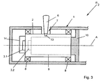
- Gemäss Figur 1 weist eine erfindungsgemässe Vorrichtung R1 zum Steuern eines hier nicht dargestellten Triebwerkes, insbesondere eines Flugzeuges ein Gehäuse 1 auf, in welchem vorzugsweise in seiner Längsrichtung ein Führungselement 2 drehbar um eine Achse A gelagert ist. Einends sitzt an dem Führungselement 2 ein Wegmesssystem 3.1 und andernends über eine Wellenkupplung 4 die Regelungseinrichtung 9, insbesondere ein Regelungsmotor auf. Diesem ist endseits ebenfalls ein Wegmesssystem 3.2 zugeordnet, welches über Verbindungsleitungen 5 mit einer Steuerung 14 in Verbindung steht.
- Das Führungselement 2 ist über Lagerelemente 8 um die Achse A verdrehbar im Gehäuse 1 gelagert.
- Das Führungselement 2 steht mit einem Gashebel 6 in Verbindung, welcher aus einem Führungsschlitz 7 aus dem Gehäuse 1 herausragt. Bevorzugt ist der Führungsschlitz 7, wie insbesondere auch in Figur 2 dargestellt, radial umlaufend im Gehäuse 1 vorgesehen.
- Dem Gashebel 6 und/oder dem Führungselement 2 ist ein Kraftsensor 13 zugeordnet, welcher ebenfalls über die Verbindungsleitung 5, sowie auch die Regelungseinrichtung 9 mit der Steuerung 14 in Verbindung steht.
- Das Wegmesssystem 3.1 kann ebenfalls mit der Steuerung 14 verbunden sein.
- Wie aus Figur 2 ersichtlich ist, lässt sich der Gashebel 6 manuell um die Achse A rotatorisch bewegen, wobei eine Bewegung auf die Wegmesssysteme 3.1, 3.2 mechanisch übertragbar ist. Diese liefern die entsprechenden Signale ggf. über einen Rechner zum Triebwerk, um das Triebwerk in Gang zu stetzen. Je nach Position des Gashebels 6 lässt sich der Betriebszustand des Triebwerkes erkennen.
- Fällt beispielsweise die Regelungsreinrichtung 9, insbesondere der Regelungsmotor aus, so lässt sich manuell durch rotatorisches Verdrehen des Führungselementes 2 mittels des Gashebels 6 das Triebwerk regeln, da die Wegmesssysteme 3.1 bzw. 3.2 die entsprechenden Signale induktiv, magnetisch oder auf optischem Wege übermitteln.
- Somit ist das Triebwerk und insbesondere die Steuerung des Triebwerkes durch einen Energieausfall, beispielsweise der Regelungseinrichtung 9, insbesondere des Regelungsmotors abgesichert.
- In dem Ausführungsbeispiel der vorliegenden Erfindung gemäss Figur 3 ist innerhalb des Führungselementes 2, wie gestrichelt dargestellt, die Regelungseinrichtung 9, insbesondere der Regelungsmotor drehbar gelagert, wobei diese miteinander im Eingriff stehen. Dabei stützt sich der Regelungsmotor bzw. die Regelungseinrichtung 9 ausserhalb des Führungselementes 2 am Gehäuse 1 ab und ist mit diesem über einen Flansch 10 wiederlösbar fest verbunden.
- Dies ermöglicht eine kompakte und kostengünstig herzustellende Bauweise.
- Wird beispielsweise mittels eines Autopiloten ein Flugzeug betrieben, so wird mittels des Regelungsmotors 9 der Gashebel 6 entsprechend der Steuerung des Flugzeuges mitbewegt, so dass der Pilot in jeder Lage den Betriebszustand des Triebwerkes anhand der Position des Gashebels 6 im Führungsschlitz erkennt.
- Gleichzeitig wird bei einem manuellen Betrieb entweder über den Regelungsmotor 9 und/oder über das Wegmesssystem 3.1, 3.2 ein Betriebszustand an einen hier nicht dargestellten Rechner des Flugzeuges übermittelt, ggf. auch über die Steuerung 14, welcher dann das entsprechende Triebwerk direkt ansteuert.
- Insbesondere ist von Vorteil bei der vorliegenden Erfindung, dass manuell der Gashebel 6 bzw. bei einem Ausfall des Regelungsmotors getätigt werden kann und dass der Pilot aufgrund der rotatorischen drehbaren Lage des Gashebels in seiner Position erkennt, in welchem Betriebszustand sich das Triebwerk zur Zeit befindet.
- Er kann manuell rein mechanisch den Gashebel verschieben, wodurch eine rotatorische Bewegung des Führungselementes 2 auf die Wegmesssysteme 3.1, 3.2 übertragen wird. Dort wird diese Drehbewegung ermittelt und an den entsprechenden Rechner zur Steuerung des Triebwerkes weitergeleitet.
- Daher ist auch beispielsweise bei einem Energieausfall eine Übermittlung des elektrischen Signales vom Wegmesssystem 3.1, 3.2 zum Triebwerk noch möglich. Dies ist bei der vorliegenden Erfindung von elementarer Bedeutung, da die Sicherheit des Flugzeuges mit einer entsprechenden Vorrichtung zum Betreiben eines Triebewerkes erheblich erhöht wird.
- Bei einem elektrischen Ausfall des Systems findet keine Selbsthemmung statt. Der Gashebel 6 kann manuell von hand bewegt werden, wobei die ursprüngliche Position und Stellung des Betriebszustandes des Triebwerkes in jeder Lage ersichtlich ist.
- Die Steuerung 14 übernimmt zumindest teilweise die geführte Bewegung des Gashebels, z.B. durch Bewegen des Führungselementes 2 mittels der Regelungseinrichtung 9, insbesondere Regelungsmotor, wenn beispielsweise der Kraftsensor 13 betätigt ist. Dann schaltet entsprechend der Regelungsmotor 9 hinzu, um die manuelle Bewegung des Gashebels 6 elektrisch zu unterstützen. Die Steuerung 14 kann externer Bestandteil des Gehäuses 1 bzw. der Regelungseinrichtung 9 sein. Dies soll vom vorliegenden Erfindungsgedanken umfasst sein.
- Fliegt das Flugzeug im Autopilotenbetrieb, so wird über die Regelungseinrichtung 9 der Gashebel entsprechend mitbewegt.
- Wird der Gashebel 6 manuell betätigt, so erfolgt eine manuelle Krafteinleitung auf den Gashebel 6, wie in Doppelpfeilrichtung gemäss Figur 2 dargestellt, mit einer Kraft F, die in dem Sensor 13 ermittelt wird. Dieser schaltet dann über die Steuerung 14 die Regelungseinrichtung 9 hinzu, so dass eine manuelle Drehbewegung des Gashebels 6 durch die Regelungseinrichtung 9, insbesondere den Regelungsmotor automatisch unterstützt und geführt wird.
- Hierdurch lässt sich sehr leicht und angenehm der Gashebel 6 um die Achse A vor oder zurückbewegen.
- Der Pilot muss keinesfalls manuell mit eigener Kraft den Gashebel 6, insbesondere das Führungselement 2 in entsprechende Drehung versetzen, um einen Betriebszustand eines angeschlossenen Triebwerkes zu verändern.
-
1 Gehäuse 34 67 2 Führungselement 35 68 3 Wegmesssystem 36 69 4 Wellenkupplung 37 70 5 Verbindungsleitung 38 71 6 Gashebel 39 72 7 Führungsschlitz 40 73 8 Lagerelement 41 74 9 Regelungseinrichtung 42 75 10 Flansch 43 76 11 44 77 12 45 78 13 Kraftsensor 46 79 14 Steuerung 47 15 48 16 49 R1 Vorrichtung 17 50 R2 Vorrichtung 18 51 19 52 20 53 21 54 22 55 F Kraft 23 56 A Achse 24 57 25 58 26 59 27 60 28 61 29 62 30 63 31 64 32 65 33 66
Claims (12)
- Vorrichtung zum Steuern eines Triebwerkes, insbesondere eines Flugzeuges mit zumindest einen in einem Gehäuse (1) bewegbar gelagerten und einem Führungselement (2) zugordneten Gashebel (6) und einer Regelungseinrichtung (9) zum zusätzlichen automatischen Antreiben des Gashebels (6),
dadurch gekennzeichnet,
dass zur Unterstützung einer manuellen, rotatorischen Bewegung des Gashebels (6) die Regelungseinrichtung (9) auf ein Signal eines dem Gashebel (6) und/oder dem Führungselement (2) zugeordneten Kraftsensors (13) einschaltbar ist. - Vorrichtung nach Anspruch 1, dadurch gekennzeichnet, dass eine rotatorische, manuelle und/oder automatisch gesteuerte Bewegung des Gashebels (6) permanent direkt oder indirekt auf ein Wegmesssystem (3.1, 3.2) mechanisch oder elektrisch übertragbar ist.
- Vorrichtung nach Anspruch 1 oder 2, dadurch gekennzeichnet, dass der Gashebel (6) dem, um eine Achse (A) drehbaren Führungselement (2) zugeordnet ist, welches direkt oder indirekt über die Regelungseinrichtung (9), insbesondere einen Regelungsmotor antreibbar ist.
- Vorrichtung nach wenigstens einem der Ansprüche 1 bis 3, dadurch gekennzeichnet, dass eine rotatorische, mechanische und/oder automatische Bewegung des Gashebels (6) mechanisch an die Bewegung eines Wegmesssystems (3.1, 3.2) gekoppelt ist.
- Vorrichtung nach wenigstens einem der Ansprüche 1 bis 4, dadurch gekennzeichnet, dass durch eine rotatorische Bewegung des Gashebels (6) das Führungselement (2) entsprechend um eine Achse (A) verdrehbar ist, wobei dem Führungselement (2) einends das Wegmesssystem (3.1) zugeordnet ist.
- Vorrichtung nach wenigstens einem der Ansprüche 1 bis 5, dadurch gekennzeichnet, dass andernends des Führungselementes (2) die Regelungseinrichtung (9) als Regelungsmotor mit ggf. einem zugeordneten Wegmesssystem (3.2) direkt oder indirekt angreift.
- Vorrichtung nach wenigstens einem der Ansprüche 1 bis 6, dadurch gekennzeichnet, dass das Wegmesssystem (3.1, 3.2) als Wegaufnehmer von induktiver, magnetischer oder optischer Art ist.
- Vorrichtung nach wenigstens einem der Ansprüche 1 bis 7, dadurch gekennzeichnet, dass das Wegmesssystem (3.1, 3.2) und/oder der Kraftsensor (13) und/oder die Regelungseinrichtung (9) mit einer Steuerung (14) in Verbindung steht, um eine manuelle Bewegung des Gashebels (6) durch Hinzuschalten der Regelungseinrichtung (9) zu unterstützen, wobei die jeweiligen Positionen des Gashebels (6) entsprechend des Betriebszustandes über die Wegmesssysteme (3.1, 3.2) an ein Triebwerk weiterleitbar sind.
- Vorrichtung nach wenigstens einem der Ansprüche 1 bis 8, dadurch gekennzeichnet, dass der Gashebel (6) in einem Führungsschlitz (7) des Gehäuses (1) geführt ist, welcher in etwa radial verlaufend zum Führungselement (2) angeordnet ist.
- Vorrichtung nach Anspruch 9, dadurch gekennzeichnet, dass das Führungselement (2) gegenüber dem Gehäuse (1) verdrehbar angeordnet ist.
- Vorrichtung nach wenigstens einem der Ansprüche 1 bis 10, dadurch gekennzeichnet, dass die Regelungseinrichtung (9), insbesondere der Regelungsmotor als interner oder externer Bestandteil mit dem Führungselement (2) im Eingriff steht.
- Vorrichtung nach wenigstens einem der Ansprüche 1 bis 11, dadurch gekennzeichnet, dass die Regelungseinrichtung (9), insbesondere der Regelungsmotor feststehend mit dem Gehäuse (1) verbunden ist.
Applications Claiming Priority (3)
| Application Number | Priority Date | Filing Date | Title |
|---|---|---|---|
| DE19926563 | 1999-06-11 | ||
| DE19926563A DE19926563A1 (de) | 1999-06-11 | 1999-06-11 | Vorrichtung zum Steuern eines Triebwerkes |
| PCT/EP2000/005135 WO2000076843A1 (de) | 1999-06-11 | 2000-06-06 | Vorrichtung zum steuern eines triebwerkes |
Publications (2)
| Publication Number | Publication Date |
|---|---|
| EP1185455A1 EP1185455A1 (de) | 2002-03-13 |
| EP1185455B1 true EP1185455B1 (de) | 2008-01-30 |
Family
ID=7910856
Family Applications (1)
| Application Number | Title | Priority Date | Filing Date |
|---|---|---|---|
| EP00938757A Expired - Lifetime EP1185455B1 (de) | 1999-06-11 | 2000-06-06 | Vorrichtung zum steuern eines triebwerkes |
Country Status (4)
| Country | Link |
|---|---|
| US (1) | US6739210B1 (de) |
| EP (1) | EP1185455B1 (de) |
| DE (2) | DE19926563A1 (de) |
| WO (1) | WO2000076843A1 (de) |
Families Citing this family (7)
| Publication number | Priority date | Publication date | Assignee | Title |
|---|---|---|---|---|
| US10604268B2 (en) * | 2017-02-22 | 2020-03-31 | Pratt & Whitney Canada Corp. | Autothrottle control for turboprop engines |
| US11479364B2 (en) * | 2017-12-13 | 2022-10-25 | Safe Flight Instrument, Llc | Aircraft torque control device |
| GB202301047D0 (en) * | 2023-01-25 | 2023-03-08 | Bae Systems Plc | Active throttle arrangement and control system |
| EP4406847A1 (de) * | 2023-01-25 | 2024-07-31 | BAE SYSTEMS plc | Aktive drosselanordnung und steuersystem |
| KR20250140544A (ko) * | 2023-01-25 | 2025-09-25 | 배 시스템즈 피엘시 | 능동 스로틀 장치 및 제어 시스템 |
| EP4406846A1 (de) * | 2023-01-25 | 2024-07-31 | BAE SYSTEMS plc | Aktive drosselanordnung und steuersystem |
| WO2024156994A1 (en) * | 2023-01-25 | 2024-08-02 | Bae Systems Plc | Active throttle arrangement and control system |
Family Cites Families (4)
| Publication number | Priority date | Publication date | Assignee | Title |
|---|---|---|---|---|
| US4039804A (en) * | 1972-03-14 | 1977-08-02 | Westinghouse Electric Corporation | System and method for monitoring industrial gas turbine operating parameters and for providing gas turbine power plant control system inputs representative thereof |
| GB2073887B (en) * | 1980-03-15 | 1984-04-26 | British Aerospace | Aircraft thrust controller |
| GB2114717B (en) * | 1982-01-22 | 1986-03-12 | British Aerospace | Control apparatus |
| GB2225125A (en) * | 1988-11-16 | 1990-05-23 | Sundstrand Corp | Turbine monitoring system |
-
1999
- 1999-06-11 DE DE19926563A patent/DE19926563A1/de not_active Ceased
-
2000
- 2000-06-06 US US10/009,074 patent/US6739210B1/en not_active Expired - Fee Related
- 2000-06-06 EP EP00938757A patent/EP1185455B1/de not_active Expired - Lifetime
- 2000-06-06 DE DE50014948T patent/DE50014948D1/de not_active Expired - Fee Related
- 2000-06-06 WO PCT/EP2000/005135 patent/WO2000076843A1/de not_active Ceased
Also Published As
| Publication number | Publication date |
|---|---|
| DE50014948D1 (de) | 2008-03-20 |
| DE19926563A1 (de) | 2000-12-14 |
| WO2000076843A1 (de) | 2000-12-21 |
| US6739210B1 (en) | 2004-05-25 |
| EP1185455A1 (de) | 2002-03-13 |
Similar Documents
| Publication | Publication Date | Title |
|---|---|---|
| EP3307603B1 (de) | Fahrzeuglenkung mit steer-by-wire-system und mechanischer rückfallebene | |
| DE19539753B4 (de) | Kraftfahrzeugtürverschluß mit Zentralverriegelungseinrichtung | |
| EP0077984B1 (de) | Stellantrieb | |
| DE4429401C2 (de) | Druckmittelbetriebener Stellantrieb | |
| DE102020206894A1 (de) | Aktuatoren zur verwendung mit einer externen steuerung | |
| DE3723205A1 (de) | Hilfskraftlenkung, insbesondere fuer kraftfahrzeuge | |
| DE102019119471A1 (de) | Steer-by-wire-Vorrichtung | |
| EP1185455B1 (de) | Vorrichtung zum steuern eines triebwerkes | |
| EP1185454B1 (de) | Vorrichtung zum steuern eines triebwerkes | |
| DE102008008978B3 (de) | Antriebsvorrichtung für einen Steuerschieber eines hydraulischen Ventils | |
| DE10342681B3 (de) | Fahrzeuglenkung mit einer Übersetzungsverhältnisänderungseinrichtung | |
| DE102010014284B4 (de) | Steuereinrichtung | |
| DE102023102659A1 (de) | Digitale Automatische Kupplung (DAK) mit elektromechanischem Aktuator für ein Schienenfahrzeug und Schienenfahrzeug mit einer solchen Kupplung | |
| DE19911892A1 (de) | Vorrichtung zur Lenkung eines Fahrzeugs | |
| EP3607641B1 (de) | Stellantrieb mit bremsvorrichtung | |
| DE102021103936B4 (de) | Stellantrieb für eine Steuerfläche eines Luftfahrzeugs | |
| EP3911877A1 (de) | Aktuatoreinheit | |
| DE10159704A1 (de) | Fahrzeuglenkung und Betätigungsmotor einer elektromechanischen Fahrzeuglenkung | |
| DE3141092C2 (de) | Optoelektronische Einstellvorrichtung | |
| DE2700928A1 (de) | Stellantrieb fuer luft- und drosselklappen, mischhaehne u.dgl. in heizungs- und lueftungsanlagen | |
| DE19911891A1 (de) | Vorrichtung zur Lenkung eines Fahrzeugs | |
| WO2009059746A2 (de) | Fahrzeug-lenksystem | |
| DE102022130957A1 (de) | Smarter redundanter leichter Aktuator | |
| CH601744A5 (en) | Electric motor rotation restrictor for valve operation | |
| WO2013057022A1 (de) | In einem kraftfahrzeug anordbare vorrichtung mit mindestens einem aktuator für eine kraftfahrzeug-steer-by-wire-lenkeinrichtung |
Legal Events
| Date | Code | Title | Description |
|---|---|---|---|
| PUAI | Public reference made under article 153(3) epc to a published international application that has entered the european phase |
Free format text: ORIGINAL CODE: 0009012 |
|
| 17P | Request for examination filed |
Effective date: 20011116 |
|
| AK | Designated contracting states |
Kind code of ref document: A1 Designated state(s): AT BE CH CY DE DK ES FI FR GB GR IE IT LI LU MC NL PT SE |
|
| RAP1 | Party data changed (applicant data changed or rights of an application transferred) |
Owner name: WITTENSTEIN AG |
|
| 17Q | First examination report despatched |
Effective date: 20021023 |
|
| RBV | Designated contracting states (corrected) |
Designated state(s): DE FR GB IT |
|
| 17Q | First examination report despatched |
Effective date: 20021023 |
|
| GRAP | Despatch of communication of intention to grant a patent |
Free format text: ORIGINAL CODE: EPIDOSNIGR1 |
|
| GRAS | Grant fee paid |
Free format text: ORIGINAL CODE: EPIDOSNIGR3 |
|
| GRAA | (expected) grant |
Free format text: ORIGINAL CODE: 0009210 |
|
| AK | Designated contracting states |
Kind code of ref document: B1 Designated state(s): DE FR GB IT |
|
| REG | Reference to a national code |
Ref country code: GB Ref legal event code: FG4D Free format text: NOT ENGLISH |
|
| REF | Corresponds to: |
Ref document number: 50014948 Country of ref document: DE Date of ref document: 20080320 Kind code of ref document: P |
|
| ET | Fr: translation filed | ||
| PLBE | No opposition filed within time limit |
Free format text: ORIGINAL CODE: 0009261 |
|
| STAA | Information on the status of an ep patent application or granted ep patent |
Free format text: STATUS: NO OPPOSITION FILED WITHIN TIME LIMIT |
|
| 26N | No opposition filed |
Effective date: 20081031 |
|
| PGFP | Annual fee paid to national office [announced via postgrant information from national office to epo] |
Ref country code: FR Payment date: 20090615 Year of fee payment: 10 Ref country code: IT Payment date: 20090624 Year of fee payment: 10 |
|
| PGFP | Annual fee paid to national office [announced via postgrant information from national office to epo] |
Ref country code: DE Payment date: 20090828 Year of fee payment: 10 Ref country code: GB Payment date: 20090618 Year of fee payment: 10 |
|
| GBPC | Gb: european patent ceased through non-payment of renewal fee |
Effective date: 20100606 |
|
| REG | Reference to a national code |
Ref country code: FR Ref legal event code: ST Effective date: 20110228 |
|
| PG25 | Lapsed in a contracting state [announced via postgrant information from national office to epo] |
Ref country code: IT Free format text: LAPSE BECAUSE OF NON-PAYMENT OF DUE FEES Effective date: 20100606 |
|
| PG25 | Lapsed in a contracting state [announced via postgrant information from national office to epo] |
Ref country code: DE Free format text: LAPSE BECAUSE OF NON-PAYMENT OF DUE FEES Effective date: 20110101 |
|
| PG25 | Lapsed in a contracting state [announced via postgrant information from national office to epo] |
Ref country code: FR Free format text: LAPSE BECAUSE OF NON-PAYMENT OF DUE FEES Effective date: 20100630 |
|
| PG25 | Lapsed in a contracting state [announced via postgrant information from national office to epo] |
Ref country code: GB Free format text: LAPSE BECAUSE OF NON-PAYMENT OF DUE FEES Effective date: 20100606 |