EP1184925A2 - PEM-Brennstoffzellenstapel - Google Patents
PEM-Brennstoffzellenstapel Download PDFInfo
- Publication number
- EP1184925A2 EP1184925A2 EP01119314A EP01119314A EP1184925A2 EP 1184925 A2 EP1184925 A2 EP 1184925A2 EP 01119314 A EP01119314 A EP 01119314A EP 01119314 A EP01119314 A EP 01119314A EP 1184925 A2 EP1184925 A2 EP 1184925A2
- Authority
- EP
- European Patent Office
- Prior art keywords
- fuel cell
- gas distribution
- cell stack
- pem fuel
- layers
- Prior art date
- Legal status (The legal status is an assumption and is not a legal conclusion. Google has not performed a legal analysis and makes no representation as to the accuracy of the status listed.)
- Withdrawn
Links
- 239000000446 fuel Substances 0.000 title claims abstract description 57
- 239000007789 gas Substances 0.000 claims abstract description 93
- 238000009826 distribution Methods 0.000 claims abstract description 77
- 239000004744 fabric Substances 0.000 claims abstract description 50
- 239000012528 membrane Substances 0.000 claims abstract description 48
- 229920000049 Carbon (fiber) Polymers 0.000 claims abstract description 41
- 239000004917 carbon fiber Substances 0.000 claims abstract description 41
- VNWKTOKETHGBQD-UHFFFAOYSA-N methane Chemical compound C VNWKTOKETHGBQD-UHFFFAOYSA-N 0.000 claims abstract description 40
- 238000006243 chemical reaction Methods 0.000 claims abstract description 22
- 239000005518 polymer electrolyte Substances 0.000 claims abstract description 15
- 239000011148 porous material Substances 0.000 claims abstract description 8
- 239000000463 material Substances 0.000 claims description 15
- 230000006835 compression Effects 0.000 claims description 13
- 238000007906 compression Methods 0.000 claims description 13
- 239000000835 fiber Substances 0.000 claims description 2
- 239000003054 catalyst Substances 0.000 description 31
- 229920001343 polytetrafluoroethylene Polymers 0.000 description 29
- 239000004810 polytetrafluoroethylene Substances 0.000 description 29
- 230000000052 comparative effect Effects 0.000 description 20
- XLYOFNOQVPJJNP-UHFFFAOYSA-N water Substances O XLYOFNOQVPJJNP-UHFFFAOYSA-N 0.000 description 14
- -1 platinum group metals Chemical class 0.000 description 10
- 239000006229 carbon black Substances 0.000 description 8
- 235000019241 carbon black Nutrition 0.000 description 8
- BASFCYQUMIYNBI-UHFFFAOYSA-N platinum Chemical group [Pt] BASFCYQUMIYNBI-UHFFFAOYSA-N 0.000 description 8
- WYTGDNHDOZPMIW-RCBQFDQVSA-N alstonine Natural products C1=CC2=C3C=CC=CC3=NC2=C2N1C[C@H]1[C@H](C)OC=C(C(=O)OC)[C@H]1C2 WYTGDNHDOZPMIW-RCBQFDQVSA-N 0.000 description 7
- 239000003365 glass fiber Substances 0.000 description 7
- 239000000725 suspension Substances 0.000 description 7
- OKTJSMMVPCPJKN-UHFFFAOYSA-N Carbon Chemical compound [C] OKTJSMMVPCPJKN-UHFFFAOYSA-N 0.000 description 6
- UFHFLCQGNIYNRP-UHFFFAOYSA-N Hydrogen Chemical compound [H][H] UFHFLCQGNIYNRP-UHFFFAOYSA-N 0.000 description 6
- DNIAPMSPPWPWGF-UHFFFAOYSA-N Propylene glycol Chemical compound CC(O)CO DNIAPMSPPWPWGF-UHFFFAOYSA-N 0.000 description 6
- HEMHJVSKTPXQMS-UHFFFAOYSA-M Sodium hydroxide Chemical compound [OH-].[Na+] HEMHJVSKTPXQMS-UHFFFAOYSA-M 0.000 description 6
- 239000001257 hydrogen Substances 0.000 description 6
- 229910052739 hydrogen Inorganic materials 0.000 description 6
- 239000000758 substrate Substances 0.000 description 6
- 229910052799 carbon Inorganic materials 0.000 description 5
- 239000011521 glass Substances 0.000 description 5
- 229920000554 ionomer Polymers 0.000 description 5
- 239000000126 substance Substances 0.000 description 5
- 229920000557 Nafion® Polymers 0.000 description 4
- QAOWNCQODCNURD-UHFFFAOYSA-N Sulfuric acid Chemical compound OS(O)(=O)=O QAOWNCQODCNURD-UHFFFAOYSA-N 0.000 description 4
- 239000011248 coating agent Substances 0.000 description 4
- 238000000576 coating method Methods 0.000 description 4
- 238000011068 loading method Methods 0.000 description 4
- 238000004519 manufacturing process Methods 0.000 description 4
- 239000000203 mixture Substances 0.000 description 4
- 239000004071 soot Substances 0.000 description 4
- 238000007605 air drying Methods 0.000 description 3
- QVGXLLKOCUKJST-UHFFFAOYSA-N atomic oxygen Chemical compound [O] QVGXLLKOCUKJST-UHFFFAOYSA-N 0.000 description 3
- 229920002313 fluoropolymer Polymers 0.000 description 3
- 239000004811 fluoropolymer Substances 0.000 description 3
- 230000002209 hydrophobic effect Effects 0.000 description 3
- 229920001600 hydrophobic polymer Polymers 0.000 description 3
- 239000000976 ink Substances 0.000 description 3
- 239000002184 metal Substances 0.000 description 3
- 229910052751 metal Inorganic materials 0.000 description 3
- 239000001301 oxygen Substances 0.000 description 3
- 229910052760 oxygen Inorganic materials 0.000 description 3
- 229920006360 Hostaflon Polymers 0.000 description 2
- 239000004743 Polypropylene Substances 0.000 description 2
- 230000002378 acidificating effect Effects 0.000 description 2
- 230000000712 assembly Effects 0.000 description 2
- 238000000429 assembly Methods 0.000 description 2
- 230000008901 benefit Effects 0.000 description 2
- 239000002131 composite material Substances 0.000 description 2
- 238000009792 diffusion process Methods 0.000 description 2
- 238000001035 drying Methods 0.000 description 2
- 230000006872 improvement Effects 0.000 description 2
- 239000007800 oxidant agent Substances 0.000 description 2
- 230000003647 oxidation Effects 0.000 description 2
- 238000007254 oxidation reaction Methods 0.000 description 2
- 239000002245 particle Substances 0.000 description 2
- 230000035515 penetration Effects 0.000 description 2
- 229910052697 platinum Inorganic materials 0.000 description 2
- 229920000642 polymer Polymers 0.000 description 2
- 229920001155 polypropylene Polymers 0.000 description 2
- 230000002940 repellent Effects 0.000 description 2
- 239000005871 repellent Substances 0.000 description 2
- 238000007789 sealing Methods 0.000 description 2
- 235000011121 sodium hydroxide Nutrition 0.000 description 2
- RZVAJINKPMORJF-UHFFFAOYSA-N Acetaminophen Chemical compound CC(=O)NC1=CC=C(O)C=C1 RZVAJINKPMORJF-UHFFFAOYSA-N 0.000 description 1
- 239000004698 Polyethylene Substances 0.000 description 1
- 229910002849 PtRu Inorganic materials 0.000 description 1
- 239000002253 acid Substances 0.000 description 1
- 239000003570 air Substances 0.000 description 1
- 239000011230 binding agent Substances 0.000 description 1
- 238000001354 calcination Methods 0.000 description 1
- 239000012876 carrier material Substances 0.000 description 1
- 238000010531 catalytic reduction reaction Methods 0.000 description 1
- 239000007795 chemical reaction product Substances 0.000 description 1
- 238000002485 combustion reaction Methods 0.000 description 1
- 239000002322 conducting polymer Substances 0.000 description 1
- 229920001940 conductive polymer Polymers 0.000 description 1
- 229920001577 copolymer Polymers 0.000 description 1
- 238000009795 derivation Methods 0.000 description 1
- 230000000694 effects Effects 0.000 description 1
- 230000005611 electricity Effects 0.000 description 1
- 239000010411 electrocatalyst Substances 0.000 description 1
- 238000000840 electrochemical analysis Methods 0.000 description 1
- 229910002804 graphite Inorganic materials 0.000 description 1
- 239000010439 graphite Substances 0.000 description 1
- 230000012447 hatching Effects 0.000 description 1
- 239000008240 homogeneous mixture Substances 0.000 description 1
- 238000005470 impregnation Methods 0.000 description 1
- 150000002739 metals Chemical class 0.000 description 1
- 238000000034 method Methods 0.000 description 1
- 230000004048 modification Effects 0.000 description 1
- 238000012986 modification Methods 0.000 description 1
- 230000000737 periodic effect Effects 0.000 description 1
- 230000002093 peripheral effect Effects 0.000 description 1
- 229920001643 poly(ether ketone) Polymers 0.000 description 1
- 229920002480 polybenzimidazole Polymers 0.000 description 1
- 229920000573 polyethylene Polymers 0.000 description 1
- 229920006254 polymer film Polymers 0.000 description 1
- 230000008092 positive effect Effects 0.000 description 1
- 230000008569 process Effects 0.000 description 1
- 230000005588 protonation Effects 0.000 description 1
- 230000009467 reduction Effects 0.000 description 1
- 238000006722 reduction reaction Methods 0.000 description 1
- 230000002787 reinforcement Effects 0.000 description 1
- 125000000542 sulfonic acid group Chemical group 0.000 description 1
- 238000009941 weaving Methods 0.000 description 1
Images


Classifications
-
- H—ELECTRICITY
- H01—ELECTRIC ELEMENTS
- H01M—PROCESSES OR MEANS, e.g. BATTERIES, FOR THE DIRECT CONVERSION OF CHEMICAL ENERGY INTO ELECTRICAL ENERGY
- H01M8/00—Fuel cells; Manufacture thereof
- H01M8/02—Details
- H01M8/0202—Collectors; Separators, e.g. bipolar separators; Interconnectors
- H01M8/0258—Collectors; Separators, e.g. bipolar separators; Interconnectors characterised by the configuration of channels, e.g. by the flow field of the reactant or coolant
- H01M8/0263—Collectors; Separators, e.g. bipolar separators; Interconnectors characterised by the configuration of channels, e.g. by the flow field of the reactant or coolant having meandering or serpentine paths
-
- H—ELECTRICITY
- H01—ELECTRIC ELEMENTS
- H01M—PROCESSES OR MEANS, e.g. BATTERIES, FOR THE DIRECT CONVERSION OF CHEMICAL ENERGY INTO ELECTRICAL ENERGY
- H01M8/00—Fuel cells; Manufacture thereof
- H01M8/02—Details
-
- B—PERFORMING OPERATIONS; TRANSPORTING
- B60—VEHICLES IN GENERAL
- B60L—PROPULSION OF ELECTRICALLY-PROPELLED VEHICLES; SUPPLYING ELECTRIC POWER FOR AUXILIARY EQUIPMENT OF ELECTRICALLY-PROPELLED VEHICLES; ELECTRODYNAMIC BRAKE SYSTEMS FOR VEHICLES IN GENERAL; MAGNETIC SUSPENSION OR LEVITATION FOR VEHICLES; MONITORING OPERATING VARIABLES OF ELECTRICALLY-PROPELLED VEHICLES; ELECTRIC SAFETY DEVICES FOR ELECTRICALLY-PROPELLED VEHICLES
- B60L50/00—Electric propulsion with power supplied within the vehicle
- B60L50/50—Electric propulsion with power supplied within the vehicle using propulsion power supplied by batteries or fuel cells
- B60L50/70—Electric propulsion with power supplied within the vehicle using propulsion power supplied by batteries or fuel cells using power supplied by fuel cells
- B60L50/72—Constructional details of fuel cells specially adapted for electric vehicles
-
- H—ELECTRICITY
- H01—ELECTRIC ELEMENTS
- H01M—PROCESSES OR MEANS, e.g. BATTERIES, FOR THE DIRECT CONVERSION OF CHEMICAL ENERGY INTO ELECTRICAL ENERGY
- H01M8/00—Fuel cells; Manufacture thereof
- H01M8/02—Details
- H01M8/0202—Collectors; Separators, e.g. bipolar separators; Interconnectors
- H01M8/023—Porous and characterised by the material
- H01M8/0234—Carbonaceous material
-
- H—ELECTRICITY
- H01—ELECTRIC ELEMENTS
- H01M—PROCESSES OR MEANS, e.g. BATTERIES, FOR THE DIRECT CONVERSION OF CHEMICAL ENERGY INTO ELECTRICAL ENERGY
- H01M8/00—Fuel cells; Manufacture thereof
- H01M8/02—Details
- H01M8/0271—Sealing or supporting means around electrodes, matrices or membranes
-
- H—ELECTRICITY
- H01—ELECTRIC ELEMENTS
- H01M—PROCESSES OR MEANS, e.g. BATTERIES, FOR THE DIRECT CONVERSION OF CHEMICAL ENERGY INTO ELECTRICAL ENERGY
- H01M8/00—Fuel cells; Manufacture thereof
- H01M8/10—Fuel cells with solid electrolytes
- H01M8/1007—Fuel cells with solid electrolytes with both reactants being gaseous or vaporised
-
- H—ELECTRICITY
- H01—ELECTRIC ELEMENTS
- H01M—PROCESSES OR MEANS, e.g. BATTERIES, FOR THE DIRECT CONVERSION OF CHEMICAL ENERGY INTO ELECTRICAL ENERGY
- H01M8/00—Fuel cells; Manufacture thereof
- H01M8/24—Grouping of fuel cells, e.g. stacking of fuel cells
- H01M8/241—Grouping of fuel cells, e.g. stacking of fuel cells with solid or matrix-supported electrolytes
- H01M8/242—Grouping of fuel cells, e.g. stacking of fuel cells with solid or matrix-supported electrolytes comprising framed electrodes or intermediary frame-like gaskets
-
- B—PERFORMING OPERATIONS; TRANSPORTING
- B60—VEHICLES IN GENERAL
- B60L—PROPULSION OF ELECTRICALLY-PROPELLED VEHICLES; SUPPLYING ELECTRIC POWER FOR AUXILIARY EQUIPMENT OF ELECTRICALLY-PROPELLED VEHICLES; ELECTRODYNAMIC BRAKE SYSTEMS FOR VEHICLES IN GENERAL; MAGNETIC SUSPENSION OR LEVITATION FOR VEHICLES; MONITORING OPERATING VARIABLES OF ELECTRICALLY-PROPELLED VEHICLES; ELECTRIC SAFETY DEVICES FOR ELECTRICALLY-PROPELLED VEHICLES
- B60L2240/00—Control parameters of input or output; Target parameters
- B60L2240/10—Vehicle control parameters
- B60L2240/36—Temperature of vehicle components or parts
-
- H—ELECTRICITY
- H01—ELECTRIC ELEMENTS
- H01M—PROCESSES OR MEANS, e.g. BATTERIES, FOR THE DIRECT CONVERSION OF CHEMICAL ENERGY INTO ELECTRICAL ENERGY
- H01M8/00—Fuel cells; Manufacture thereof
- H01M8/02—Details
- H01M8/0271—Sealing or supporting means around electrodes, matrices or membranes
- H01M8/0273—Sealing or supporting means around electrodes, matrices or membranes with sealing or supporting means in the form of a frame
-
- H—ELECTRICITY
- H01—ELECTRIC ELEMENTS
- H01M—PROCESSES OR MEANS, e.g. BATTERIES, FOR THE DIRECT CONVERSION OF CHEMICAL ENERGY INTO ELECTRICAL ENERGY
- H01M8/00—Fuel cells; Manufacture thereof
- H01M8/02—Details
- H01M8/0271—Sealing or supporting means around electrodes, matrices or membranes
- H01M8/028—Sealing means characterised by their material
- H01M8/0282—Inorganic material
-
- H—ELECTRICITY
- H01—ELECTRIC ELEMENTS
- H01M—PROCESSES OR MEANS, e.g. BATTERIES, FOR THE DIRECT CONVERSION OF CHEMICAL ENERGY INTO ELECTRICAL ENERGY
- H01M8/00—Fuel cells; Manufacture thereof
- H01M8/24—Grouping of fuel cells, e.g. stacking of fuel cells
- H01M8/2457—Grouping of fuel cells, e.g. stacking of fuel cells with both reactants being gaseous or vaporised
-
- H—ELECTRICITY
- H01—ELECTRIC ELEMENTS
- H01M—PROCESSES OR MEANS, e.g. BATTERIES, FOR THE DIRECT CONVERSION OF CHEMICAL ENERGY INTO ELECTRICAL ENERGY
- H01M8/00—Fuel cells; Manufacture thereof
- H01M8/24—Grouping of fuel cells, e.g. stacking of fuel cells
- H01M8/2465—Details of groupings of fuel cells
- H01M8/247—Arrangements for tightening a stack, for accommodation of a stack in a tank or for assembling different tanks
- H01M8/248—Means for compression of the fuel cell stacks
-
- Y—GENERAL TAGGING OF NEW TECHNOLOGICAL DEVELOPMENTS; GENERAL TAGGING OF CROSS-SECTIONAL TECHNOLOGIES SPANNING OVER SEVERAL SECTIONS OF THE IPC; TECHNICAL SUBJECTS COVERED BY FORMER USPC CROSS-REFERENCE ART COLLECTIONS [XRACs] AND DIGESTS
- Y02—TECHNOLOGIES OR APPLICATIONS FOR MITIGATION OR ADAPTATION AGAINST CLIMATE CHANGE
- Y02E—REDUCTION OF GREENHOUSE GAS [GHG] EMISSIONS, RELATED TO ENERGY GENERATION, TRANSMISSION OR DISTRIBUTION
- Y02E60/00—Enabling technologies; Technologies with a potential or indirect contribution to GHG emissions mitigation
- Y02E60/30—Hydrogen technology
- Y02E60/50—Fuel cells
-
- Y—GENERAL TAGGING OF NEW TECHNOLOGICAL DEVELOPMENTS; GENERAL TAGGING OF CROSS-SECTIONAL TECHNOLOGIES SPANNING OVER SEVERAL SECTIONS OF THE IPC; TECHNICAL SUBJECTS COVERED BY FORMER USPC CROSS-REFERENCE ART COLLECTIONS [XRACs] AND DIGESTS
- Y02—TECHNOLOGIES OR APPLICATIONS FOR MITIGATION OR ADAPTATION AGAINST CLIMATE CHANGE
- Y02T—CLIMATE CHANGE MITIGATION TECHNOLOGIES RELATED TO TRANSPORTATION
- Y02T90/00—Enabling technologies or technologies with a potential or indirect contribution to GHG emissions mitigation
- Y02T90/40—Application of hydrogen technology to transportation, e.g. using fuel cells
Definitions
- the invention relates to a PEM fuel cell stack of stacked one above the other Membrane electrode units, gas distribution layers and bipolar plates.
- the invention relates to such PEM fuel cell stacks which consist of gas distribution layers woven carbon fibers included.
- Fuel cells locally convert a fuel and an oxidizing agent from one another separated by two electrodes into electricity, heat and water.
- a fuel can Hydrogen or a hydrogen-rich gas, oxygen or air as the oxidizing agent serve.
- the process of energy conversion in the fuel cell stands out with a particularly high degree of efficiency. For this reason, fuel cells win in combination with electric motors it is becoming increasingly important as an alternative for conventional internal combustion engines.
- PEM fuel cell polymer electrolyte fuel cell
- a PEM fuel cell stack is used as a stack Understanding the arrangement ("stack") of fuel cell units.
- a fuel cell unit is also briefly referred to below as a fuel cell. It contains one membrane electrode unit (MEE) each, which is between bipolar plates, also called separator plates, is arranged for gas supply and power line.
- MEE membrane electrode unit
- a membrane electrode assembly consists of a polymer electrolyte membrane that is based on is provided on both sides with reaction layers, the electrodes. One of the reaction layers is as an anode for the oxidation of hydrogen and the second reaction layer designed as a cathode for the reduction of oxygen.
- Anode and cathode contain so-called Electrocatalysts, which the respective reaction (oxidation of hydrogen respectively Catalytic reduction.
- a catalytically active Components are preferably the metals of the platinum group of the periodic table Elements used.
- So-called supported catalysts are used in the majority, in which the catalytically active platinum group metals in highly disperse form the surface of a conductive substrate has been applied. The average crystallite size the platinum group metals is approximately between 1 and 10 nm.
- carrier materials finely divided carbon blacks have proven their worth.
- the polymer electrolyte membrane consists of proton-conducting polymer materials. These materials are also referred to as ionomers below. Prefers is a tetrafluoroethylene-fluorovinyl ether copolymer with acid functions, in particular Sulfonic acid groups used. Such a material is, for example, under the Trade names Nafion® by E.I. DuPont distributed. However, there are others, in particular fluorine-free ionomer materials, such as sulfonated polyether ketones or aryl ketones or polybenzimidazoles can be used.
- An essential prerequisite for an increase in cell performance is optimal Supply and discharge of the respective reactive gas mixtures to and from the catalytically active ones Centers of the catalyst layers.
- the ionomer material of the anode must be constantly exposed to water vapor (dampening water) be moistened to ensure optimal proton conductivity. That on water formed in the cathode (water of reaction) must be continuously removed, flooding the pore system of the cathode and thus obstructing the supply to avoid with oxygen.
- US Pat. No. 4,293,396 describes a gas diffusion electrode that consists of an open-pore conductive carbon fiber fabric. Contain the pores of the carbon fiber fabric a homogeneous mixture of catalyzed carbon particles and hydrophobic Particles of a binder material.
- German patent application DE 195 44 323 A1 provides a gas diffusion electrode for polymer electrolyte fuel cells, which contains a carbon fiber fabric with Soot and polytetrafluoroethylene is impregnated.
- EP 0 869 568 A1 describes a gas distribution layer made of a carbon fiber fabric for Membrane electrode units described.
- a compensation layer made of soot and coated with a fluoropolymer that is porous and water repellent and at the same time is electrically conductive and also has a reasonably smooth surface.
- Prefers this leveling layer does not penetrate more than half of the carbon fiber fabric on.
- the carbon fiber fabric can improve its water repellent properties be pretreated with a mixture of carbon black and a fluoropolymer.
- WO 97/13287 describes a gas distribution layer (here "intermediate layer"), by infiltrating and / or coating one side of a coarse-pore carbon substrate (Carbon paper, graphite paper or carbon felt) with a composition is made of carbon black and a fluoropolymer, which has the porosity of a near-surface Part of the carbon substrate is reduced and / or a discrete layer is reduced Porosity forms on the surface of the substrate.
- the gas distribution layer is with this Coating applied to the catalyst layers of membrane electrode units. As in EP 0 869 568 A1, it is among other things the task of the coating to make good electrical contact with the catalyst layers.
- US 6,007,933 describes a fuel cell unit made of stacked one above the other Membrane electrode units and bipolar plates. Between the membrane electrode units and elastic gas distribution layers are arranged on the bipolar plates. to The bipolar plates provide the membrane electrode units with reactive gases open on one side on their contact surfaces facing the gas distribution layers Gas distribution channels. The fuel cell unit is used to improve the electrical contact between the gas distribution layers and the membrane electrode assemblies assembled under pressure. There is a risk that the elastic Penetrate gas distribution layers in the gas distribution channels which are open on one side and thus hinder gas transport and the electrical performance of the fuel cell affect. This is prevented, for example, by perforated carrier plates that between gas distribution layers and bipolar plates. To seal the Membrane electrode units become O-ring seals and seals made of PTFE films used.
- a PEM fuel cell stack comprising one or more fuel cells (1) arranged one above the other, each of which contains a membrane electrode unit (2) between two electrically conductive bipolar plates (3, 4), which have flow channels (1) open on one side ( 10) are equipped for the supply of reactive gases, the membrane electrode units each having a polymer electrolyte membrane (5) which is in contact with a reaction layer (6, 7) on each side, the reaction layers having a smaller area than have the polymer electrolyte membrane and a compressible, coarse-pore gas distribution layer (8,9) made of carbon fiber fabric as well as seals (11, 12) are inserted between each reaction layer and the adjacent bipolar plates, congruent with the reaction layers, whereby the Gasver divider layers in the unloaded state have a thickness D 1 and the seals have a thickness D 2 .
- the PEM fuel cell stack is characterized in that the gas distribution layers in the PEM fuel cell stack are compressed to 25 to 60% of their original thickness.
- the cell resistance (resistance of an individual membrane electrode unit) is reduced by defined compression of the woven gas distribution layers. Compression of the gas distribution layers to 30 to 50%, in particular 35 to 40% of their original thickness D 1 is preferred. Experience has shown that the specific resistance of the carbon fiber fabric can be reduced to below 6 m ⁇ • cm by compression. The porosity of the gas distribution layer is also reduced to 20 to 70% of the original porosity, so that flooding of the pores by water of reaction is avoided. Both effects significantly improve the electrical performance of the fuel cell stack.
- the defined compression can be set in a simple manner by using seals made of incompressible material, the thickness D 2 of which is smaller than the thickness D 1 of the compressible gas distribution layers in the unloaded state.
- the compressible gas distribution layers are compressed to the thickness of the seals, so that the compression of the fuel cell stack is given by the ratio D 2 / D 1 .
- materials or material composites are referred to as incompressible if their compressibility is less than 5%, preferably less than 1%, of the compressibility of the gas distribution layers.
- Seals made of polytetrafluoroethylene (PTFE) are preferred, which meet the above condition by reinforcement with glass fibers.
- the flow channels of the bipolar plates are with inlet and outlet channels for the Reactive gases connected outside the surface of the membrane electrode assemblies in a peripheral area of the bipolar plates perpendicularly through the entire plate stack are led.
- the flow channels are between the inlet and outlet channels on the contact surfaces of the bipolar plates usually in the form of rectangular Meandering or serpentine arranged.
- the PEM fuel cell stack according to the invention is now obtained when the weaving direction of the carbon fiber fabric of the gas distribution layers at an angle ⁇ of 20 to 70, preferably from 30 to 60, and in particular from 45 °, to the flow channels the bipolar plates is rotated, or when the carbon fiber fabric in such a structure is woven that at least 60% of the fibers have an angle of Have at least 30 ° to the channel structure of the bipolar plates.
- a further improvement in the transport properties and the water balance of the Gas distribution layers are obtained because the penetration of the tissue into the gas distribution channels and thus further reduces the obstruction of the gas flow in the channels becomes.
- the same positive effect is obtained even when the gas distribution channels be arranged in a suitable pattern on the bipolar plates.
- the PEM fuel cell stacks according to the invention have good access to the Reactive gases to the catalytically active centers of the membrane electrode units, one effective moistening of the ionomer in the catalyst layers and the membrane and the problem-free removal of the reaction product water from the cathode side of the membrane electrode units.
- Coarse-pored carbon fiber fabrics with porosities of 50 to 95% can be used.
- various basic materials that differ in structure, manufacturing process and Distinguish properties. Examples of such materials are AvCarb 1071 HCB from Textron Inc. or Panex 30 from Zoltek, Inc.
- the commercial, coarse-pored carbon fiber fabrics can be used with hydrophobic Be polymer impregnated.
- Suitable hydrophobic polymers are polyethylene, Polypropylene, polytetrafluoroethylene or other organic or inorganic, hydrophobic materials. Suspensions of polytetrafluoroethylene are preferred or polypropylene used for impregnation.
- the loading of the carbon fiber substrates with a hydrophobic polymer depending on the application, between 3 and 30 % By weight. Loads between 4 and 20% by weight have proven particularly useful.
- the loading of the gas distribution layers of the anode and cathode can vary his.
- the impregnated carbon fiber substrates are under strong air exchange dried at temperatures up to 250 ° C.
- Drying is particularly preferred in a forced air drying cabinet at 60 to 220, preferably at 80 to 140 ° C. Subsequently the hydrophobic polymer is sintered. This happens for example with PTFE at a temperature of 330 to 400 ° C.
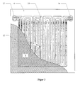
- FIG 1 shows a cross section through a PEM fuel cell stack (1), which for the sake of clarity, there is only one membrane electrode unit (2).
- (5) denotes the polymer electrolyte membrane, which is on both sides with the Catalyst layers (6) and (7) is in contact.
- the areal expansion of the catalyst layers is smaller than that of the membrane, so that the polymer electrolyte membrane protrudes on all sides beyond the catalyst layers and thus a coating-free Edge forms.
- the gas distribution layers are a perfect fit on the catalyst layers (8) and (9).
- the gas distribution layers are from both sides the bipolar plates (3, 4) with the gas distribution channels (10) are placed on them.
- two perforated seals 11 and 12
- the Hole area is adapted to the expansion of the catalyst layers.
- Incompressible polymer films or polymer composite films are preferred as seals (11 and 12) such as glass fiber reinforced PTFE films.
- seals 11 and 12
- glass fiber reinforced PTFE films When assembling the fuel cell stack, the entire stack is screwed together pressed in the direction perpendicular to the polymer electrolyte membrane. The thickness of the sealing films is therefore chosen so that after assembly the compressible gas distribution layers are compressed to the required extent.
- FIG. 2 shows a top view of the bipolar plate (4) corresponding to FIG. 1, view A, with applied gas distribution layer (9) and seal (12).
- Gas distribution layer (9) and The seal (12) is only partially drawn in the top view and leaves the view free on the channel structure of the bipolar plate.
- the gas distribution channels (10) are in one Double serpentine structure arranged and connect the inflow channel (13) with the Drain channel (14), both of which run vertically through the cell stack.
- Figure 2 indicates the hatching of the gas distribution layer (9) the usual orientation of the fabric structure perpendicular and parallel relative to the main directions of expansion of the gas distribution channels on.
- the cross section of the PEM fuel cell stack according to FIG. 1 corresponds the section B-B of Figure 2.
- Figure 3 is except for the orientation of the carbon fiber fabric of the gas distribution layer (9) identical to Figure 2.
- the carbon fiber fabric with its fabric structure according to the preferred embodiment of the invention by the angle ⁇ 45 ° twisted against the main directions of expansion of the gas distribution channels.
- Carbon fiber fabric of the type AvCarb 1071 HCB from Textron Inc. with a basis weight of 115 g / m 2 and a thickness of 380 ⁇ m was immersed in a suspension of PTFE in water (Hostaflon TF5235, Dyneon GmbH). The material was removed after a few seconds. After the suspension adhering to the surface had run out, the carbon fiber fabric was dried in a forced-air drying cabinet at 110 ° C. To fuse the PTFE introduced into the structure, the impregnated carbon fiber fabric was sintered in a chamber furnace at 340 to 350 ° C for about 15 minutes.
- carbon fiber fabrics By adjusting the PTFE concentrations in the suspension, carbon fiber fabrics became with a PTFE content of 14.5 ⁇ 0.5% by weight for the anode and 6.5 ⁇ 0.5 % By weight for the cathode of a fuel cell.
- the average thickness of the finished carbon fiber fabric was 330 ⁇ m.
- the catalyst coated membrane used here was made in the following way:
- the polymer electrolyte membrane and the ionomer for the reaction layers were used in their non-acidic form and after completion of the manufacturing process again with the help of sulfuric acid in its acidic, proton-conductive modification transferred.
- Ink A catalyst 40% Pt on carbon black Vulcan® XC-72 5.53 g Nafion solution 4.2% by weight in propylene glycol 43.92 g caustic soda 15% by weight in water 0.59 g
- Ink B Catalyst: 40% PtRu (1: 1) on carbon black Vulcan® XC-72 5.45 g Nafion solution 4.2% by weight in propylene glycol 43.13 g caustic soda 15% by weight in water 0.59 g
- the ink A was screen-printed onto a Nafion® 112 membrane (thickness 50 ⁇ m) in the Na + form and dried at 90 ° C. Then, the back of the membrane was coated with the catalyst ink B in the same manner to form the anode layer. The reverse protonation was carried out in 0.5 M sulfuric acid.
- the platinum loading of the cathode layer was 0.4 mg Pt / cm 2 , that of the anode layer 0.3 mg Pt / cm 2 . This corresponded to a total loading of the coated membrane with platinum of 0.7 mg / cm 2 .
- the layer thicknesses ranged between 15 and 20 ⁇ m.
- the printed area was 50 cm 2 each.
- Carbon fiber fabric of the type AvCarb 1071 HCB from Textron Inc. with a basis weight of 115 g / m 2 and a thickness of 380 ⁇ m was immersed in a suspension of PTFE in water (Hostaflon TF5235, Dyneon GmbH). The material was removed after a few seconds. After the suspension adhering to the surface had run out, the carbon fiber fabric was dried in a forced-air drying cabinet at 110 ° C. To fuse the PTFE introduced into the structure, the impregnated carbon fiber fabric was sintered in a chamber furnace at 340 to 350 ° C for about 15 minutes.
- carbon fiber papers were made with a PTFE content of 14.5 ⁇ 0.5% by weight for the anode and 6.5 ⁇ 0.5 % By weight for the cathode of a fuel cell.
- the average thickness of the finished carbon fiber fabric was 330 ⁇ m.
- the carbon fiber fabrics were hydrophobized and sintered as described in Example 1.
- the PTFE content was 14.5 ⁇ 0.5% by weight for the anode and 6.5 ⁇ 0.5% by weight for the cathode.
- the carbon fiber fabrics were hydrophobized and sintered as described in Example 1.
- the PTFE content was 14.5 ⁇ 0.5% by weight for the anode and 6.5 ⁇ 0.5% by weight for the cathode.
- Two chemical glass seals (incompressible, glass fiber reinforced PTFE, 0.27 mm thick) with a total thickness of 0.54 mm. Together with a thickness of the catalyst layer of 20 ⁇ m in each case can be calculated from this compression of the gas distribution layers to 75.8% of the original thickness.
- the carbon fiber fabrics were hydrophobized and sintered as described in Example 1.
- the PTFE content was 14.5 ⁇ 0.5% by weight for the anode and 6.5 ⁇ 0.5% by weight for the cathode.
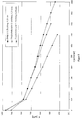
- FIG. 6 shows the comparison of the performance data of the cells according to Example 1 and 2.
- the cell temperature was 75 ° C.
- the working pressure of the reactive gases was 1 bar.
- the hydrogen content of the reformate was 45% by volume.
- the CO concentration was 50 ppm. 3 vol.% Air was added to the anode gas to increase the fuel cell output added. It can be seen that the fuel cell stacks according to the invention with the inventive Gas distribution layers have a significantly improved electrical performance deliver compared to the prior art (VB1).
- Table 1 shows the cell voltages still measured when the cells were loaded with a current density of 600 mA / cm 2 .
- Cell voltages in reformate / air operation at 600 mA / cm 2 example Cell voltage [mV] Comparative Example 1 599 example 1 609 Comparative Example 2 585 Comparative Example 3 480
- Examples 1 and 2 show improved performance compared to the comparative examples 2 and 3. Also compared to those with a soot / PTFE compensation layer provided gas distribution layers from Comparative Example 1 is a small one Performance advantage at low and high current densities. The main advantage here is however, that the costly production of the soot / PTFE compensation layer is eliminated.
Landscapes
- Engineering & Computer Science (AREA)
- Sustainable Energy (AREA)
- Life Sciences & Earth Sciences (AREA)
- Sustainable Development (AREA)
- Chemical Kinetics & Catalysis (AREA)
- Chemical & Material Sciences (AREA)
- Manufacturing & Machinery (AREA)
- Electrochemistry (AREA)
- General Chemical & Material Sciences (AREA)
- Power Engineering (AREA)
- Transportation (AREA)
- Mechanical Engineering (AREA)
- Fuel Cell (AREA)
- Inert Electrodes (AREA)
Abstract
Description
- Figur 1:
- Querschnitt durch einen PEM-Brennstoffzellenstapel, welches eine Membran-Elektrodeneinheit enthält
- Figur 2:
- Aufsicht auf eine Bipolarplatte mit aufgelegter Gasverteilerschicht und Dichtung
- Figur 3:
- Aufsicht auf eine Bipolarplatte mit aufgelegter Gasverteilerschicht und Dichtung
- Figur 4:
- Zellspannung in Abhängigkeit von der Stromdichte bei Reformat/Luftbetrieb für die MEE von Beispiel 1 und Vergleichsbeispiel 1.
- Figur 5:
- Zellspannung in Abhängigkeit von der Stromdichte bei Reformat/Luftbetrieb für die MEE von Beispiel 1, Vergleichsbeispiel 2 und Vergleichsbeispiel 3.
- Figur 6:
- Zellspannung in Abhängigkeit von der Stromdichte bei Reformat/Luftbetrieb für die MEE von Beispiel 1 und 2.
| Tinte A: | Katalysator | 40 % Pt auf Ruß Vulcan® XC-72 | 5,53 g |
| Nafion-Lösung | 4,2 Gew.-% in Propylenglykol | 43,92 g | |
| Natronlauge | 15 Gew.-% in Wasser | 0,59 g | |
| Tinte B: | Katalysator: | 40 % PtRu (1:1) auf Ruß Vulcan® XC-72 | 5,45 g |
| Nafion-Lösung | 4,2 Gew.-% in Propylenglykol | 43,13 g | |
| Natronlauge | 15 Gew.-% in Wasser | 0,59 g |
| Zellspannungen im Reformat/Luftbetrieb bei 600 mA/cm2 | |
| Beispiel | Zellspannung [mV] |
| Vergleichsbeispiel 1 | 599 |
| Beispiel 1 | 609 |
| Vergleichsbeispiel 2 | 585 |
| Vergleichsbeispiel 3 | 480 |
| Beispiel 2 | 612 |
Claims (7)
- PEM-Brennstoffzellenstapel aus einer oder mehreren übereinander angeordneten Brennstoffzellen (1), die jeweils eine Membran-Elektrodeneinheit (2) zwischen zwei elektrisch leitfähige Bipolarplatten (3,4) enthalten, welche auf ihren Oberflächen mit einseitig offenen Strömungskanälen (10) für die Zuführung von Reaktivgasen ausgerüstet sind, wobei die Membran-Elektrodeneinheiten jeweils eine Polymerelektrolyt-Membran (5) aufweisen, die auf jeder Seite jeweils mit einer Reaktionsschicht (6,7) in Kontakt steht, wobei die Reaktionsschichten eine geringere flächige Ausdehnung als die Polymerelektrolyt-Membran besitzen und zwischen jeder Reaktionsschicht und den angrenzenden Bipolarplatten deckungsgleich zu den Reaktionsschichten jeweils eine kompressible, grobporige Gasverteilerschicht (8,9) aus Kohlefasergewebe sowie im Bereich außerhalb der durch die Gasverteilerschichten abgedeckten Fläche Dichtungen (11,12) eingefügt sind, wobei die Gasverteilerschichten im unbelasteten Zustand eine Dicke D1 und die Dichtungen eine Dicke D2 aufweisen,
dadurch gekennzeichnet, daß die Gasverteilerschichten im PEM-Brennstoffzellenstapel auf 25 bis 60% ihrer ursprünglichen Dicke komprimiert sind. - PEM-Brennstoffzellenstapel nach Anspruch 1,
dadurch gekennzeichnet, daß die Dichtungen (9) aus inkompressiblem Material bestehen und die Komprimierung des Brennstoffzellenstapels durch das Verhältnis D2/D1 gegeben ist. - PEM-Brennstoffzellenstapel nach Anspruch 1,
dadurch gekennzeichnet, daß das die Porosität der eingesetzten Gasverteilerschichten durch Kompression auf 20 bis 70% und ihr elektrischer Widerstand auf unter 6 mΩ · cm vermindert wird. - PEM-Brennstoffzellenstapel nach einem der Ansprüche 1 bis 3,
dadurch gekennzeichnet, daß die Geweberichtung des Kohlefasergewebes unter einem Winkel von 20 bis 70° zu den Strömungskanälen der Bipolarplatten angeordnet ist. - PEM-Brennstoffzellenstapel nach einem der Ansprüche 1 bis 3,
dadurch gekennzeichnet, daß die Geweberichtung des Kohlefasergewebes unter einem Winkel von 30 bis 60° zu den Strömungskanälen der Bipolarplatten angeordnet ist. - PEM-Brennstoffzellenstapel nach einem der Ansprüche 1 bis 3,
dadurch gekennzeichnet, daß das Kohlefasergewebe in einer solchen Struktur gewebt ist, daß mindestens 60% der Fasern einen Winkel von mindestens 30° zur Kanalstruktur der Bipolarplatten aufweisen. - Elektroautomobil enthaltend ein PEM-Brennstoffzellenstapel zur elektrischen Energieversorgung,
dadurch gekennzeichnet, daß ein PEM-Brennstoffzellenstapel nach einem der Ansprüche 1 bis 6 eingesetzt wird.
Applications Claiming Priority (2)
| Application Number | Priority Date | Filing Date | Title |
|---|---|---|---|
| DE10042744 | 2000-08-31 | ||
| DE10042744A DE10042744A1 (de) | 2000-08-31 | 2000-08-31 | PEM-Brennstoffzellenstapel |
Publications (2)
| Publication Number | Publication Date |
|---|---|
| EP1184925A2 true EP1184925A2 (de) | 2002-03-06 |
| EP1184925A3 EP1184925A3 (de) | 2006-09-20 |
Family
ID=7654404
Family Applications (1)
| Application Number | Title | Priority Date | Filing Date |
|---|---|---|---|
| EP01119314A Withdrawn EP1184925A3 (de) | 2000-08-31 | 2001-08-10 | PEM-Brennstoffzellenstapel |
Country Status (7)
| Country | Link |
|---|---|
| US (1) | US6720104B2 (de) |
| EP (1) | EP1184925A3 (de) |
| JP (1) | JP2002110198A (de) |
| KR (1) | KR100856337B1 (de) |
| BR (1) | BR0103791A (de) |
| CA (1) | CA2356094C (de) |
| DE (1) | DE10042744A1 (de) |
Cited By (3)
| Publication number | Priority date | Publication date | Assignee | Title |
|---|---|---|---|---|
| FR2899386A1 (fr) * | 2006-03-29 | 2007-10-05 | Peugeot Citroen Automobiles Sa | Assemblage elementaire d'une pile a combustible comprenant un composant elastique. |
| DE102004017501C5 (de) * | 2003-04-14 | 2009-12-24 | General Motors Corp. (N.D.Ges.D. Staates Delaware), Detroit | Brennstoffzelle, Brennstoffzellenstapel, Verfahren zu deren Herstellung sowie Verwendung der Brennstoffzelle |
| WO2018108552A1 (de) * | 2016-12-12 | 2018-06-21 | Robert Bosch Gmbh | Bipolarplatte für eine brennstoffzelle und brennstoffzelle |
Families Citing this family (33)
| Publication number | Priority date | Publication date | Assignee | Title |
|---|---|---|---|---|
| NL1014696C2 (nl) * | 2000-03-20 | 2001-09-28 | Stichting Energie | Vervaardiging van lage-temperatuur brandstofcel elektroden. |
| AU2001219539A1 (en) * | 2000-09-05 | 2002-03-22 | Wesley L. Bradford | Reverse osmosis membrane and process for making same |
| JP2002313359A (ja) * | 2001-04-17 | 2002-10-25 | Mitsubishi Heavy Ind Ltd | 固体高分子型燃料電池 |
| EP1341251A1 (de) * | 2002-02-28 | 2003-09-03 | OMG AG & Co. KG | PEM-Brennstoffzellenstapel |
| US20040157111A1 (en) * | 2002-11-28 | 2004-08-12 | Shigeru Sakamoto | Fuel cell |
| JP2004214019A (ja) * | 2002-12-27 | 2004-07-29 | Nissan Motor Co Ltd | 燃料電池 |
| US7303835B2 (en) * | 2003-01-15 | 2007-12-04 | General Motors Corporation | Diffusion media, fuel cells, and fuel cell powered systems |
| JP4236156B2 (ja) * | 2003-01-31 | 2009-03-11 | 日立マクセル株式会社 | 燃料電池 |
| CN100573971C (zh) * | 2003-06-27 | 2009-12-23 | 超电池公司 | 微燃料电池结构 |
| WO2005020346A2 (en) * | 2003-06-27 | 2005-03-03 | Ultracell Corporation | Micro fuel cell architecture |
| US20080233436A1 (en) * | 2003-07-28 | 2008-09-25 | General Motors Corporation | Diffusion media tailored to account for variations in operating humidity and devices incorporating the same |
| US7332240B2 (en) * | 2003-07-28 | 2008-02-19 | General Motors Corporation | Spatially varying diffusion media and devices incorporating the same |
| US20050026012A1 (en) * | 2003-07-28 | 2005-02-03 | O'hara Jeanette E. | Diffusion media tailored to account for variations in operating humidity and devices incorporating the same |
| US20050092175A1 (en) * | 2003-10-29 | 2005-05-05 | Meacham G.B. K. | Noble metal gas barriers |
| US7074255B2 (en) * | 2003-10-29 | 2006-07-11 | Meacham G B Kirby | Noble metal gas barriers |
| US7803476B2 (en) * | 2003-11-07 | 2010-09-28 | Gm Global Technology Operations, Inc. | Electrical contact element for a fuel cell having a conductive monoatomic layer coating |
| US20050100774A1 (en) * | 2003-11-07 | 2005-05-12 | Abd Elhamid Mahmoud H. | Novel electrical contact element for a fuel cell |
| US20050255368A1 (en) * | 2004-05-12 | 2005-11-17 | Ultracell Corporation, A California Corporation | High surface area micro fuel cell architecture |
| US8101319B2 (en) * | 2004-05-20 | 2012-01-24 | GM Global Technology Operations LLC | Approach to make a high performance membrane electrode assembly (MEA) for a PEM fuel cell |
| CN100521329C (zh) * | 2005-01-14 | 2009-07-29 | 松下电器产业株式会社 | 燃料电池用堆栈以及燃料电池 |
| US20060237034A1 (en) * | 2005-04-20 | 2006-10-26 | Lawrence Shore | Process for recycling components of a PEM fuel cell membrane electrode assembly |
| US8124261B2 (en) * | 2006-06-20 | 2012-02-28 | Basf Corporation | Process for recycling components of a PEM fuel cell membrane electrode assembly |
| CN101728553A (zh) * | 2006-06-21 | 2010-06-09 | 松下电器产业株式会社 | 燃料电池 |
| KR101481187B1 (ko) * | 2009-12-03 | 2015-01-09 | 현대자동차주식회사 | 연료전지용 기체확산층및 그 제조방법 |
| KR101282620B1 (ko) * | 2010-12-03 | 2013-07-12 | 기아자동차주식회사 | 냉해동 내구성이 우수한 연료전지 스택 및 그 제조방법 |
| WO2014006817A1 (ja) | 2012-07-02 | 2014-01-09 | パナソニック株式会社 | 固体高分子型燃料電池用の膜電極接合体とその製造方法および固体高分子型燃料電池 |
| WO2017221699A1 (ja) * | 2016-06-20 | 2017-12-28 | パナソニックIpマネジメント株式会社 | 燃料電池 |
| JP2018106927A (ja) * | 2016-12-27 | 2018-07-05 | ダイハツ工業株式会社 | 燃料電池 |
| CN110890569A (zh) * | 2019-12-06 | 2020-03-17 | 浙江锋源氢能科技有限公司 | 燃料电池组件、燃料电池及其制备工艺 |
| CN111146472B (zh) * | 2020-01-09 | 2023-09-22 | 李肖宏 | 一种氢燃料电池 |
| DE102021108981A1 (de) | 2021-04-12 | 2022-10-13 | Audi Aktiengesellschaft | Brennstoffzellenstapel mit komprimierbarer Gewebestruktur |
| CN115411331B (zh) * | 2021-05-28 | 2026-03-17 | 未势能源科技有限公司 | 燃料电池堆的假膜电极组件、燃料电池堆和车辆 |
| CN114232014B (zh) * | 2021-12-15 | 2025-04-11 | 中国科学院大连化学物理研究所 | 一种双极板和固体氧化物电解池堆及其应用 |
Family Cites Families (16)
| Publication number | Priority date | Publication date | Assignee | Title |
|---|---|---|---|---|
| JPH07135001A (ja) * | 1993-11-12 | 1995-05-23 | Toyota Motor Corp | 燃料電池および燃料電池用電極 |
| ATE245852T1 (de) * | 1995-10-06 | 2003-08-15 | Dow Global Technologies Inc | Fluessigkeitsverteilungsstrukturen fuer membran- elektrode-anordnungen von brennstoffzellen |
| US5798187A (en) * | 1996-09-27 | 1998-08-25 | The Regents Of The University Of California | Fuel cell with metal screen flow-field |
| JP3773325B2 (ja) * | 1997-03-17 | 2006-05-10 | ジャパンゴアテックス株式会社 | 高分子固体電解質燃料電池用ガス拡散層材料及びその接合体 |
| JPH11204114A (ja) * | 1998-01-20 | 1999-07-30 | Daikin Ind Ltd | 電極材料 |
| US6096450A (en) * | 1998-02-11 | 2000-08-01 | Plug Power Inc. | Fuel cell assembly fluid flow plate having conductive fibers and rigidizing material therein |
| US6007933A (en) * | 1998-04-27 | 1999-12-28 | Plug Power, L.L.C. | Fuel cell assembly unit for promoting fluid service and electrical conductivity |
| DE19840517A1 (de) * | 1998-09-04 | 2000-03-16 | Manhattan Scientifics Inc | Gasdiffusionsstruktur senkrecht zur Membran von Polymerelektrolyt-Membran Brennstoffzellen |
| JP3951484B2 (ja) * | 1998-12-16 | 2007-08-01 | トヨタ自動車株式会社 | 燃料電池 |
| US6399234B2 (en) * | 1998-12-23 | 2002-06-04 | Utc Fuel Cells, Llc | Fuel cell stack assembly with edge seal |
| US6503654B2 (en) * | 1999-05-19 | 2003-01-07 | George A. Marchetti | Thin graphite bipolar plate with associated gaskets and carbon cloth flow-field for use in an ionomer membrane fuel cell |
| EP1073138B1 (de) * | 1999-07-26 | 2012-05-02 | Tigers Polymer Corporation | Dichtungsanordnung für Brennstoffzelle und Verfahren zum Formen der Abdichtung aus Kautschuk |
| US6303245B1 (en) * | 1999-08-27 | 2001-10-16 | Plug Power Inc. | Fuel cell channeled distribution of hydration water |
| US6261711B1 (en) * | 1999-09-14 | 2001-07-17 | Plug Power Inc. | Sealing system for fuel cells |
| US6521367B2 (en) * | 2000-12-06 | 2003-02-18 | Utc Fuel Cells, Llc | Fuel cell with an electrolyte dry-out barrier |
| US6627035B2 (en) * | 2001-01-24 | 2003-09-30 | Gas Technology Institute | Gas diffusion electrode manufacture and MEA fabrication |
-
2000
- 2000-08-31 DE DE10042744A patent/DE10042744A1/de not_active Ceased
-
2001
- 2001-08-10 EP EP01119314A patent/EP1184925A3/de not_active Withdrawn
- 2001-08-21 US US09/933,121 patent/US6720104B2/en not_active Expired - Fee Related
- 2001-08-28 JP JP2001258420A patent/JP2002110198A/ja active Pending
- 2001-08-29 CA CA002356094A patent/CA2356094C/en not_active Expired - Fee Related
- 2001-08-29 KR KR1020010052456A patent/KR100856337B1/ko not_active Expired - Fee Related
- 2001-08-30 BR BR0103791-9A patent/BR0103791A/pt not_active Application Discontinuation
Cited By (5)
| Publication number | Priority date | Publication date | Assignee | Title |
|---|---|---|---|---|
| DE102004017501C5 (de) * | 2003-04-14 | 2009-12-24 | General Motors Corp. (N.D.Ges.D. Staates Delaware), Detroit | Brennstoffzelle, Brennstoffzellenstapel, Verfahren zu deren Herstellung sowie Verwendung der Brennstoffzelle |
| US7749634B2 (en) | 2003-04-14 | 2010-07-06 | Gm Global Technology Operations, Inc. | Flow control for multiple stacks |
| FR2899386A1 (fr) * | 2006-03-29 | 2007-10-05 | Peugeot Citroen Automobiles Sa | Assemblage elementaire d'une pile a combustible comprenant un composant elastique. |
| WO2018108552A1 (de) * | 2016-12-12 | 2018-06-21 | Robert Bosch Gmbh | Bipolarplatte für eine brennstoffzelle und brennstoffzelle |
| US11309549B2 (en) | 2016-12-12 | 2022-04-19 | Robert Bosch Gmbh | Bipolar plate for a fuel cell and fuel cell |
Also Published As
| Publication number | Publication date |
|---|---|
| US20020051901A1 (en) | 2002-05-02 |
| EP1184925A3 (de) | 2006-09-20 |
| KR20020018106A (ko) | 2002-03-07 |
| US6720104B2 (en) | 2004-04-13 |
| KR100856337B1 (ko) | 2008-09-04 |
| DE10042744A1 (de) | 2002-03-28 |
| JP2002110198A (ja) | 2002-04-12 |
| CA2356094A1 (en) | 2002-02-28 |
| CA2356094C (en) | 2009-08-11 |
| BR0103791A (pt) | 2002-05-07 |
Similar Documents
| Publication | Publication Date | Title |
|---|---|---|
| EP1184925A2 (de) | PEM-Brennstoffzellenstapel | |
| EP1176653B1 (de) | Membran-Elektrodeneinheit für Polymerelektrolyt-Brennstoffzellen und Verfahren zu ihrer Herstellung | |
| DE102008046403B4 (de) | Sauerstoffentwicklungsreaktionskatalysatoren enthaltende Elektroden | |
| DE19812592B4 (de) | Membran-Elektroden-Einheit für Polymer-Elektrolyt-Brennstoffzellen, Verfahren zu ihrer Herstellung sowie Tinte | |
| EP0968542B1 (de) | Gasdiffusionselektrode mit verringertem diffusionsvermögen für wasser und polymerelektrolytmembran-brennstoffzelle | |
| DE10393467B4 (de) | Membranelektrodenanordnung und Verfahren zum Herstellen einer Elektrode für eine Membran-Elektrodenanordnung | |
| DE60004594T2 (de) | Geschichtete Kohlenstoffelektrode für elektrochemische Zellen | |
| DE102010004054B4 (de) | Verfahren zum Ausbilden einer Membranelektrodenanordnung | |
| DE102008009724B4 (de) | Diffusionsmedium zur Verwendung in einer PEM-Brennstoffzelle | |
| EP1150369B1 (de) | Gasverteilerstrukturen und Gasdiffusionselektroden für Polymerelektrolyt-Brennstoffzellen | |
| EP1261057B1 (de) | Verfahren zur Herstellung einer Membran-Elektrodeneinheit und dadurch hergestellte Membran-Elektrodeneinheit | |
| EP1341251A1 (de) | PEM-Brennstoffzellenstapel | |
| DE102012220628B4 (de) | Brennstoffzellenmembran mit auf Nanofaser getragenen Katalysatoren, Brennstoffzelle und Verfahren zur Herstellung der Membran | |
| DE102014213555A1 (de) | Membran-Elektroden-Einheit | |
| DE102010017397A1 (de) | Membranelektrodenanordnung und Brennstoffzelle | |
| DE112020001053T5 (de) | Kathodenkatalysatorschicht für eine Brennstoffzelle, und Brennstoffzelle | |
| DE112005002678B4 (de) | Anordnung für eine Brennstoffzelle und Membranelektrodenanordnung | |
| DE112004001685B4 (de) | Vorrichtung mit einer Membranelektrodenanordnung und Verfahren zum Herstellen einer Membranelektrodenanordnung | |
| DE10052189B4 (de) | Mehrschichtige Gasdiffusionselektrode einer Polymerelektrolytmembran-Brennstoffzelle, Membranelektrodenanordnung, Verfahren zur Herstellung einer Gasdiffusionselektrode und einer Membranelektrodenanordnung sowie Verwendung der Membranelektrodenanordnung | |
| DE102007025207A1 (de) | Gasdiffusionselektrode und diese enthaltende Membran-Elektroden-Einheit für eine Brennstoffzelle | |
| EP1150370A2 (de) | Gasverteilerstrukturen und Gasdiffusionselektroden für Polymerelektrolyt-Brennstoffzellen | |
| EP2229703B1 (de) | Brennstoffzelle, protonen leitende membran, membran-elektroden- einheit, verwendungen von ionomeren und kit | |
| DE102007031280A1 (de) | Gasdiffusionselektrode und diese enthaltende Membran-Elektroden-Einheit für eine Brennstoffzelle | |
| DE112012001206T5 (de) | Brennstoffzellen-System | |
| DE102010063254A1 (de) | Membran-Elektroden-Anordnung mit zwei Deckschichten |
Legal Events
| Date | Code | Title | Description |
|---|---|---|---|
| PUAI | Public reference made under article 153(3) epc to a published international application that has entered the european phase |
Free format text: ORIGINAL CODE: 0009012 |
|
| 17P | Request for examination filed |
Effective date: 20010810 |
|
| AK | Designated contracting states |
Kind code of ref document: A2 Designated state(s): AT BE CH CY DE DK ES FI FR GB GR IE IT LI LU MC NL PT SE TR |
|
| AX | Request for extension of the european patent |
Free format text: AL;LT;LV;MK;RO;SI |
|
| RAP1 | Party data changed (applicant data changed or rights of an application transferred) |
Owner name: UMICORE AG & CO. KG |
|
| PUAL | Search report despatched |
Free format text: ORIGINAL CODE: 0009013 |
|
| AK | Designated contracting states |
Kind code of ref document: A3 Designated state(s): AT BE CH CY DE DK ES FI FR GB GR IE IT LI LU MC NL PT SE TR |
|
| AX | Request for extension of the european patent |
Extension state: AL LT LV MK RO SI |
|
| AKX | Designation fees paid |
Designated state(s): AT BE CH CY DE DK ES FI FR GB GR IE IT LI LU MC NL PT SE TR |
|
| 17Q | First examination report despatched |
Effective date: 20071106 |
|
| GRAP | Despatch of communication of intention to grant a patent |
Free format text: ORIGINAL CODE: EPIDOSNIGR1 |
|
| STAA | Information on the status of an ep patent application or granted ep patent |
Free format text: STATUS: THE APPLICATION IS DEEMED TO BE WITHDRAWN |
|
| 18D | Application deemed to be withdrawn |
Effective date: 20100922 |