EP1184326B1 - Seilaufzug mit Antrieb im Aufzugsschacht - Google Patents
Seilaufzug mit Antrieb im Aufzugsschacht Download PDFInfo
- Publication number
- EP1184326B1 EP1184326B1 EP00830563A EP00830563A EP1184326B1 EP 1184326 B1 EP1184326 B1 EP 1184326B1 EP 00830563 A EP00830563 A EP 00830563A EP 00830563 A EP00830563 A EP 00830563A EP 1184326 B1 EP1184326 B1 EP 1184326B1
- Authority
- EP
- European Patent Office
- Prior art keywords
- winch
- cage
- shaft
- counterweight
- cable
- Prior art date
- Legal status (The legal status is an assumption and is not a legal conclusion. Google has not performed a legal analysis and makes no representation as to the accuracy of the status listed.)
- Expired - Lifetime
Links
Images

Classifications
-
- B—PERFORMING OPERATIONS; TRANSPORTING
- B66—HOISTING; LIFTING; HAULING
- B66B—ELEVATORS; ESCALATORS OR MOVING WALKWAYS
- B66B11/00—Main component parts of lifts in, or associated with, buildings or other structures
-
- B—PERFORMING OPERATIONS; TRANSPORTING
- B66—HOISTING; LIFTING; HAULING
- B66B—ELEVATORS; ESCALATORS OR MOVING WALKWAYS
- B66B11/00—Main component parts of lifts in, or associated with, buildings or other structures
- B66B11/0035—Arrangement of driving gear, e.g. location or support
- B66B11/0045—Arrangement of driving gear, e.g. location or support in the hoistway
-
- B—PERFORMING OPERATIONS; TRANSPORTING
- B66—HOISTING; LIFTING; HAULING
- B66B—ELEVATORS; ESCALATORS OR MOVING WALKWAYS
- B66B11/00—Main component parts of lifts in, or associated with, buildings or other structures
- B66B11/0065—Roping
- B66B11/008—Roping with hoisting rope or cable operated by frictional engagement with a winding drum or sheave
Definitions
- the present invention relates to a cable lift.
- a cable lift requires the presence of two distinct and separate compartments which may be called the “machine room” and "travel shaft".
- the former which is usually positioned above the latter, houses a hoisting winch together with the associated electrical control circuits; the latter on the other hand contains a cage for transporting persons, which is connected to the winch by means of a cable system and provided with a keyboard allowing selection of the desired floor to be stopped at, and a counterweight which, acting in opposition to the weight of the cage, allows a reduction in the force required by the winch to displace the cage and generation, between cable and pulley, of the friction required to prevent slipping of the said cable.
- Brushless motors use permanent magnets.
- the gradual demagnetisation of the magnets results in a loss of rapidity.
- Any mechanical blockage on the guides may be eliminated only by supplying a large quantity of power which, causing jerks and jolts, results in loss of continuity in mechanical control over the cage
- Positioning of the winch along the upper part of the guides also results in a less efficient sliding action of the said guides on the anchoring brackets, in particular when the cage must perform long travel movements, as well as deformation due to the excessive peak load.
- Asynchronous motors used in combination with a reduction unit occupy a large amount of space due to the use of reduction units consisting of an endless screw/helical crown wheel pair, said units also having a low output and therefore requiring the use of high-power motors and therefore the consumption of a large quantity of electrical energy.
- the reduction unit is situated in a position which is hidden from the operator and this means that the latter must control displacement of the cage solely by releasing the break and therefore in a somewhat unsafe manner.
- the object of the present invention is therefore to eliminate the abovementioned drawbacks
- the invention achieves the object using a compact winch arranged so that its axis of rotation is parallel to the wall of the shaft and the cage next to which it is arranged.
- a cage moving system devised so that the counterweight has a travel movement approximately equal to half that of the cage, therefore leaving free above it the space necessary for housing the winch there in the most advantageous position.
- the main advantage obtained by means of the present invention consists essentially in the fact that it is possible to avoid the need for two separate compartments for housing the winch and the cage and, at the same time, provide the possibility of direct mechanical and visual control over the winch and the cage in emergency situations, i.e. when manual intervention by the operator is required.
- the latter owing to the space available for housing the winch, it is possible to position the latter at a height allowing immediate viewing thereof by a person of normal height, for example at a height of between one and two metres from the ground of the highest floor reached by the cage.
- the winch may also be positioned on any side of the shaft.
- mechanical parts such as alternating-current induction motors or disk rather than drum brakes, allows a highly reliable and safe performance to be achieved, together with low energy consumption and reduced installation costs.
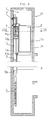
- the invention relates to a cable lift of the type with a single compartment or shaft (1) for housing a movable cage (2) and an apparatus (3) for displacement of the cage (2).
- the apparatus (3) comprises at least one fixed winch (4), provided with a traction pulley (4c) over which a cable (6) travels, and a movable counterweight (5).
- the cable lift has the special feature that, for any displacement of the cage (2), the counterweight (5) performs travel movements shorter than those of the said cage (2) so that a part (1a) of the shaft (1) is always free so as to allow the winch (4) to be housed therein.
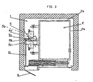
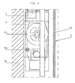
- the winch may be positioned between any wall (1b) of the shaft (1) and any wall (2a) of the cage (2) inside the part (1a) of the shaft (1) situated above the counterweight (5), i.e. approximately at the height of the last floor at which the cage (2) stops, and may be oriented so that the traction pulley (4c) has an axis of rotation (4a) parallel to the walls (1b,2a) next to which it is arranged.
- the drive pulley (5a) has an axis of rotation (5b) transversaly arranged in respect of the axis of rotation (4e) of the traction pulley (4c). Therefore, the winch (4) may be housed in the shaft (1) directly above the counterweight (5), without increasing the transversal dimension of the shaft (1).
- the advantage arising therefrom consists in the fact that the guides of the cage (2) are able to slide freely in the anchoring elements, ensuring at the same time safe, silent and comfortable operation.
- the axis (4a) of the pulley (4c) of the winch (4) it is recommended that it be arranged at a height (4), with respect to the last floor at which the cage (2) stops, of between sixty centimetres and two metres ten centimetres, so as to allow direct frontal viewing of the winch (4) when, in emergency or maintenance situations, direct intervention by an operator is required.
- a hatch (9) is provided, allowing access to the part (1a) of the shaft (1) where the winch (4) is housed.
- the latter comprises a seat (4b) for engagement of a tool (11) so that movement thereof may be manually and visually controlled, without the need for servocontrol systems. Therefore, in the event of an emergency, once the hatch (9) has been opened, the operator need merely insert the tool (11) (generally consisting of a rod) into the corresponding seat (4b), release the brake and, by means of the abovementioned tool (11), manually rotate the pulley (4c) and displace the cage (2), while keeping direct control, also visually, over the whole situation and achieving the same level of a safety which exists in a lift (10) with a separate machine room.
Landscapes
- Engineering & Computer Science (AREA)
- Civil Engineering (AREA)
- Mechanical Engineering (AREA)
- Structural Engineering (AREA)
- Lift-Guide Devices, And Elevator Ropes And Cables (AREA)
- Types And Forms Of Lifts (AREA)
- Cage And Drive Apparatuses For Elevators (AREA)
- Flexible Shafts (AREA)
- Jib Cranes (AREA)
Claims (9)
- Seilaufzug mit einer einzelnen Abteilung bzw. einem einzelnen Schacht (1) zur Unterbringung eines beweglichen Käfigs (2) und einer Vorrichtung (3), die mindestens eine feste Winde (4) und ein bewegliches Gegengewicht (5) zur Verschiebung des Käfigs (2) umfasst, worin das Gegengewicht (5) für jegliche Verschiebung des Käfigs (2) kürzere Bewegungen als die des Käfigs (2) ausführt, und worin die Winde (4) eine Zugriemenscheibe (4c) mit einer Drehachse (4a) umfasst und das Gegengewicht (5) mindestens eine Antriebsriemenscheibe (5a) mit einer Drehachse (5a) umfasst; dadurch gekennzeichnet, dass ein oberer Teil (1a) des Schachtes (1) immer frei ist, um die Unterbringung der Winde (4) darin zu ermöglichen, über dem Gegengewicht (5), zwischen einer Wand (1b) des Schachtes (1) und einer Wand (2a) des Käfigs (2), da die Drehachse (4a) der Zugriemenscheibe (4c) und die Drehachse (5b) der Antriebsriemenscheibe (5a) nicht parallel sind.
- Seilaufzug nach Patentanspruch 1, dadurch gekennzeichnet, dass die Winde (4) neben einer der Wände (1b) des Schachtes (1) im oberen Teil (1a) des Schachtes über dem Gegengewicht (5) angebracht ist.
- Seilaufzug nach Patentanspruch 2, dadurch gekennzeichnet, dass die Winde (4) eine Zugriemenscheibe (4c) beinhaltet, deren Drehachse (4a) sich parallel zu der Wand (1b) befindet, neben der sie angebracht ist.
- Seilaufzug nach Patentanspruch 1 oder 2 oder 3, dadurch gekennzeichnet, dass ein Ende (6a) des Kabels (6) am Käfig (2) befestigt ist, und das andere Ende (6b) am oberen Teil (1a) des Schachtes (1) befestigt ist, der nie durch das Gegengewicht (5) besetzt wird, sodass der Hub des Kabels (6) über die Riemenscheibe (5a) zu einer Verschiebung des Gegengewichts (5) führt, die ungefähr der Hälfte derjenigen des Käfigs (2) entspricht.
- Kabelaufzug nach Patentanspruch 1 oder 2 oder 3 oder 4, dadurch gekennzeichnet, dass er eine Halterung (7) für die Winde (4) beinhaltet, die an einer Wand (1b) des Schachtes (1) befestigt ist, sodass die Winde (4) unabhängig von den Strukturen ist, welche den Käfig (2) halten und führen.
- Seilaufzug nach Patentanspruch 5, dadurch gekennzeichnet, dass das Ende (6b) des Kabels (6) an der Halterung (7) der Winde (4) angebracht ist, um die Lärmverbreitung der Vorrichtung (3) einzuschränken.
- Kabelaufzug nach Patentanspruch 1, dadurch gekennzeichnet, dass er eine Luke (9) beinhaltet, die Zugang zum oberen Teil (1a) des Schachtes (1), in dem die Winde (4) untergebracht ist, bietet.
- Seilaufzug nach einem der vorherigen Patentansprüche, dadurch gekennzeichnet, dass sich die Achse (4a) der Riemenscheibe (4c) in Hinsicht auf den letzten Stock, an dem der Käfig (2) anhält, auf einer Höhe (h) zwischen sechzig Zentimetern und zwei Meter, zehn Zentimetern befindet, um eine direkte Vorderansicht der Winde (4) zu ermöglichen.
- Seilaufzug nach einem der vorherigen Patentansprüche, dadurch gekennzeichnet, dass die Winde (4) einen Sitz (4b) zur Anbringung eines Werkzeugs (11) umfasst, um ihre Bewegung angemessen manuell und visuell zu steuern und zu kontrollieren.
Priority Applications (16)
| Application Number | Priority Date | Filing Date | Title |
|---|---|---|---|
| DE60028029T DE60028029D1 (de) | 2000-08-07 | 2000-08-07 | Seilaufzug mit Antrieb im Aufzugsschacht |
| ES00830563T ES2263443T3 (es) | 2000-08-07 | 2000-08-07 | Ascensor de cable con maquinaria en el hueco. |
| EP00830563A EP1184326B1 (de) | 2000-08-07 | 2000-08-07 | Seilaufzug mit Antrieb im Aufzugsschacht |
| AT00830563T ATE326420T1 (de) | 2000-08-07 | 2000-08-07 | Seilaufzug mit antrieb im aufzugsschacht |
| PCT/IT2001/000427 WO2002012107A1 (en) | 2000-08-07 | 2001-08-01 | Cable lift with in shaft machinery |
| YU9503A YU9503A (sh) | 2000-08-07 | 2001-08-01 | Kablovski lift sa pogonskom mašinom u oknu |
| AU2001284401A AU2001284401A1 (en) | 2000-08-07 | 2001-08-01 | Cable lift with in shaft machinery |
| CNB018152570A CN1260111C (zh) | 2000-08-07 | 2001-08-01 | 井道机械内的绳索升降装置 |
| RU2003106423/11A RU2003106423A (ru) | 2000-08-07 | 2001-08-01 | Канатный лифт с шахтным оборудованием |
| CZ2003347A CZ2003347A3 (cs) | 2000-08-07 | 2001-08-01 | Lanový výtah |
| KR10-2003-7001708A KR20030042448A (ko) | 2000-08-07 | 2001-08-01 | 샤프트 기계장치 내부에 구비된 케이블 리프트 |
| JP2002517414A JP2004521838A (ja) | 2000-08-07 | 2001-08-01 | シャフト機構を有するケーブルリフト |
| US10/344,035 US7108105B2 (en) | 2000-08-07 | 2001-08-01 | Cable lift without a machine room |
| CA002418803A CA2418803A1 (en) | 2000-08-07 | 2001-08-01 | Cable lift with in shaft machinery |
| PL01363436A PL363436A1 (en) | 2000-08-07 | 2001-08-01 | Cable lift with in shaft machinery |
| HU0400311A HUP0400311A2 (en) | 2000-08-07 | 2001-08-01 | Cable lift with in shaft machinery |
Applications Claiming Priority (1)
| Application Number | Priority Date | Filing Date | Title |
|---|---|---|---|
| EP00830563A EP1184326B1 (de) | 2000-08-07 | 2000-08-07 | Seilaufzug mit Antrieb im Aufzugsschacht |
Publications (2)
| Publication Number | Publication Date |
|---|---|
| EP1184326A1 EP1184326A1 (de) | 2002-03-06 |
| EP1184326B1 true EP1184326B1 (de) | 2006-05-17 |
Family
ID=8175443
Family Applications (1)
| Application Number | Title | Priority Date | Filing Date |
|---|---|---|---|
| EP00830563A Expired - Lifetime EP1184326B1 (de) | 2000-08-07 | 2000-08-07 | Seilaufzug mit Antrieb im Aufzugsschacht |
Country Status (16)
| Country | Link |
|---|---|
| US (1) | US7108105B2 (de) |
| EP (1) | EP1184326B1 (de) |
| JP (1) | JP2004521838A (de) |
| KR (1) | KR20030042448A (de) |
| CN (1) | CN1260111C (de) |
| AT (1) | ATE326420T1 (de) |
| AU (1) | AU2001284401A1 (de) |
| CA (1) | CA2418803A1 (de) |
| CZ (1) | CZ2003347A3 (de) |
| DE (1) | DE60028029D1 (de) |
| ES (1) | ES2263443T3 (de) |
| HU (1) | HUP0400311A2 (de) |
| PL (1) | PL363436A1 (de) |
| RU (1) | RU2003106423A (de) |
| WO (1) | WO2002012107A1 (de) |
| YU (1) | YU9503A (de) |
Families Citing this family (6)
| Publication number | Priority date | Publication date | Assignee | Title |
|---|---|---|---|---|
| WO2007069922A1 (en) * | 2005-12-15 | 2007-06-21 | Fisher & Paykel Healthcare Limited | Breathing assistance apparatus |
| JP2010184791A (ja) * | 2009-02-13 | 2010-08-26 | Toshiba Elevator Co Ltd | エレベータ |
| US20110101198A1 (en) * | 2009-10-30 | 2011-05-05 | Thyssenkrupp Northern Elevator Corporation | "l" shaped support device for a hoisting machine in a machine roomless elevator |
| FI125157B (fi) * | 2011-11-08 | 2015-06-15 | Kone Corp | Hissijärjestelmä |
| EP3006386B1 (de) * | 2013-06-07 | 2021-10-06 | Otis Elevator Company | Aufzug mit geringem schachtkopf und geringer grube |
| WO2017167719A1 (de) * | 2016-03-31 | 2017-10-05 | Inventio Ag | Verfahren und montagevorrichtung zum durchführen eines installationsvorgangs in einem aufzugschacht einer aufzuganlage |
Family Cites Families (22)
| Publication number | Priority date | Publication date | Assignee | Title |
|---|---|---|---|---|
| FI82823C (fi) * | 1988-10-04 | 1991-04-25 | Kone Oy | Hiss. |
| FI98210C (fi) * | 1993-06-28 | 1997-05-12 | Kone Oy | Järjestely hissikoneiston liittämiseksi rakennukseen |
| US6148962A (en) * | 1993-06-28 | 2000-11-21 | Kone Oy | Traction sheave elevator, hoisting unit and machine space |
| FI95456C (fi) * | 1994-05-04 | 1996-02-12 | Kone Oy | Järjestely hissikuilun seinän aukossa ja kojetaulu |
| US5690578A (en) * | 1996-04-29 | 1997-11-25 | General Motors Corporation | Ravigneaux planetary gear transmission |
| EP0820954A1 (de) * | 1996-07-25 | 1998-01-28 | Chiu Nan Wang | Notfluchtvorrichtung für Aufzug |
| DE19752232C2 (de) * | 1997-03-26 | 2001-06-21 | Heinzerling Gmbh | Seilaufzug mit in den Aufzugschacht hineinragenden Betonsockel |
| CN1097026C (zh) * | 1997-09-26 | 2002-12-25 | 东芝株式会社 | 电梯 |
| DE19902853C2 (de) * | 1998-01-26 | 2001-10-11 | Guenter Kintrup | Personen-Seilaufzug |
| US6247557B1 (en) * | 1998-04-28 | 2001-06-19 | Kabushiki Kaisha Toshiba | Traction type elevator apparatus |
| SG91827A1 (en) * | 1998-09-28 | 2002-10-15 | Inventio Ag | Emergency release device |
| US6039152A (en) * | 1998-10-30 | 2000-03-21 | Otis Elevator Company | Elevator system with controller located under elevator landing |
| FI111622B (fi) * | 1999-01-27 | 2003-08-29 | Kone Corp | Vetopyörähissi ja taittopyörän käyttö |
| JP2000247560A (ja) * | 1999-02-26 | 2000-09-12 | Mitsubishi Electric Corp | エレベーター装置 |
| ATE306455T1 (de) * | 1999-08-19 | 2005-10-15 | Inventio Ag | Aufzugsanlage mit einer in einem aufzugsschacht angeordneten antriebseinheit |
| EP1224142B1 (de) * | 1999-10-11 | 2005-09-07 | Inventio Ag | Seilaufzug |
| JP3480403B2 (ja) * | 1999-12-09 | 2003-12-22 | 株式会社日立製作所 | エレベーター |
| SG100645A1 (en) * | 2000-03-31 | 2003-12-26 | Inventio Ag | Auxiliary device for displacing a payload receptacle of a lift and device for monitoring the position and the movement of a cage in a shaft of a lift |
| WO2001087755A1 (de) * | 2000-05-19 | 2001-11-22 | Inventio Ag | Betätigungseinrichtung für den notbetrieb einer getrieblosen antriebsmaschine eines aufzuges |
| US6619433B1 (en) * | 2000-07-24 | 2003-09-16 | Otis Elevator Company | Elevator system using minimal building space |
| DE50104314D1 (de) * | 2000-07-29 | 2004-12-02 | Alpha Getriebebau Gmbh | Aufzugskabine mit einer in diese integrierten treibscheiben-antriebsmaschine |
| JP2002167137A (ja) * | 2000-11-29 | 2002-06-11 | Toshiba Corp | エレベータ |
-
2000
- 2000-08-07 DE DE60028029T patent/DE60028029D1/de not_active Expired - Lifetime
- 2000-08-07 EP EP00830563A patent/EP1184326B1/de not_active Expired - Lifetime
- 2000-08-07 AT AT00830563T patent/ATE326420T1/de not_active IP Right Cessation
- 2000-08-07 ES ES00830563T patent/ES2263443T3/es not_active Expired - Lifetime
-
2001
- 2001-08-01 AU AU2001284401A patent/AU2001284401A1/en not_active Abandoned
- 2001-08-01 CA CA002418803A patent/CA2418803A1/en not_active Abandoned
- 2001-08-01 WO PCT/IT2001/000427 patent/WO2002012107A1/en not_active Application Discontinuation
- 2001-08-01 YU YU9503A patent/YU9503A/sh unknown
- 2001-08-01 PL PL01363436A patent/PL363436A1/xx not_active Application Discontinuation
- 2001-08-01 KR KR10-2003-7001708A patent/KR20030042448A/ko not_active Application Discontinuation
- 2001-08-01 CN CNB018152570A patent/CN1260111C/zh not_active Expired - Fee Related
- 2001-08-01 RU RU2003106423/11A patent/RU2003106423A/ru not_active Application Discontinuation
- 2001-08-01 CZ CZ2003347A patent/CZ2003347A3/cs unknown
- 2001-08-01 US US10/344,035 patent/US7108105B2/en not_active Expired - Fee Related
- 2001-08-01 HU HU0400311A patent/HUP0400311A2/hu unknown
- 2001-08-01 JP JP2002517414A patent/JP2004521838A/ja active Pending
Also Published As
| Publication number | Publication date |
|---|---|
| US20040026179A1 (en) | 2004-02-12 |
| PL363436A1 (en) | 2004-11-15 |
| DE60028029D1 (de) | 2006-06-22 |
| CN1260111C (zh) | 2006-06-21 |
| CZ2003347A3 (cs) | 2004-08-18 |
| CA2418803A1 (en) | 2002-02-14 |
| ES2263443T3 (es) | 2006-12-16 |
| AU2001284401A1 (en) | 2002-02-18 |
| EP1184326A1 (de) | 2002-03-06 |
| JP2004521838A (ja) | 2004-07-22 |
| KR20030042448A (ko) | 2003-05-28 |
| US7108105B2 (en) | 2006-09-19 |
| ATE326420T1 (de) | 2006-06-15 |
| HUP0400311A2 (en) | 2004-05-28 |
| YU9503A (sh) | 2004-11-25 |
| CN1452585A (zh) | 2003-10-29 |
| WO2002012107A1 (en) | 2002-02-14 |
| WO2002012107A8 (en) | 2003-03-06 |
| RU2003106423A (ru) | 2004-07-10 |
Similar Documents
| Publication | Publication Date | Title |
|---|---|---|
| US4402386A (en) | Self-powered elevator using a linear electric motor as counterweight | |
| EP0606875B1 (de) | Aufzugsmotor im Gegengewicht eingesetzt | |
| CA2126583C (en) | Elevator drive machine placed in the counterweight | |
| US6631790B2 (en) | Method for braking a traction sheave elevator, traction sheave elevator and use of an emergency power supply | |
| JP2877745B2 (ja) | トラクションシーブエレベータとトラクションシーブエレベータ用機械空間 | |
| KR100430113B1 (ko) | 엘리베이터 장치 | |
| JPH0470236B2 (de) | ||
| EP1184326B1 (de) | Seilaufzug mit Antrieb im Aufzugsschacht | |
| BR112020018020A2 (pt) | Processo para montagem de uma instalação de elevador | |
| JP2004504997A (ja) | エレベータケージ内に組込まれた駆動プーリ式駆動機械を備えたエレベータケージ | |
| EP0415218B1 (de) | Einstellung eines Treibers für einen Aufzug | |
| ES2244176T3 (es) | Sistema de ascenso con motor de accionamiento situado adyacente a puerta de la caja del ascensor. | |
| CA2342324C (en) | Conveyance system | |
| KR100871819B1 (ko) | 플로어들 사이에 배치된 엘리베이터를 승강시키기 위한비상장치 | |
| JP4089237B2 (ja) | エレベータの安全装置 | |
| WO2021008701A1 (en) | Elevator with an elevator car safety device acting on the stator beam | |
| EP1428784A2 (de) | Aufzugsanlage ohne Maschinenraum, mit Riemen- und/oder Kettenantrieb | |
| EP1422184A2 (de) | Maschinenraumloser Aufzug | |
| ES1046291U (es) | Dispositivo de rescate aplicable ascensores. | |
| JP2005132508A (ja) | エレベータ用ブレーキ装置 | |
| ITPR20010094A1 (it) | Apparato di movimentazione cabine o piattaforme mobili, | |
| GB2033862A (en) | Escalator auxiliary drive | |
| ITMI20000680U1 (it) | Impianto ascensore con azionamento elettrico | |
| EP1227996A2 (de) | Seilbremse für eine balanziervorrichtung |
Legal Events
| Date | Code | Title | Description |
|---|---|---|---|
| PUAI | Public reference made under article 153(3) epc to a published international application that has entered the european phase |
Free format text: ORIGINAL CODE: 0009012 |
|
| AK | Designated contracting states |
Kind code of ref document: A1 Designated state(s): AT BE CH CY DE DK ES FI FR GB GR IE IT LI LU MC NL PT SE |
|
| AX | Request for extension of the european patent |
Free format text: AL;LT;LV;MK;RO;SI |
|
| 17P | Request for examination filed |
Effective date: 20020822 |
|
| AKX | Designation fees paid |
Free format text: AT BE CH CY DE DK ES FI FR GB GR IE IT LI LU MC NL PT SE |
|
| AXX | Extension fees paid |
Free format text: AL PAYMENT 20020822;LT PAYMENT 20020822;LV PAYMENT 20020822;MK PAYMENT 20020822;RO PAYMENT 20020822;SI PAYMENT 20020822 |
|
| 17Q | First examination report despatched |
Effective date: 20040719 |
|
| GRAP | Despatch of communication of intention to grant a patent |
Free format text: ORIGINAL CODE: EPIDOSNIGR1 |
|
| GRAS | Grant fee paid |
Free format text: ORIGINAL CODE: EPIDOSNIGR3 |
|
| RAP1 | Party data changed (applicant data changed or rights of an application transferred) |
Owner name: MELLINI, PAOLO |
|
| GRAA | (expected) grant |
Free format text: ORIGINAL CODE: 0009210 |
|
| RAP1 | Party data changed (applicant data changed or rights of an application transferred) |
Owner name: SPACE LIFT SRL |
|
| AK | Designated contracting states |
Kind code of ref document: B1 Designated state(s): AT BE CH CY DE DK ES FI FR GB GR IE IT LI LU MC NL PT SE |
|
| AX | Request for extension of the european patent |
Extension state: AL LT LV MK RO SI |
|
| PG25 | Lapsed in a contracting state [announced via postgrant information from national office to epo] |
Ref country code: FI Free format text: LAPSE BECAUSE OF FAILURE TO SUBMIT A TRANSLATION OF THE DESCRIPTION OR TO PAY THE FEE WITHIN THE PRESCRIBED TIME-LIMIT Effective date: 20060517 Ref country code: NL Free format text: LAPSE BECAUSE OF FAILURE TO SUBMIT A TRANSLATION OF THE DESCRIPTION OR TO PAY THE FEE WITHIN THE PRESCRIBED TIME-LIMIT Effective date: 20060517 Ref country code: LI Free format text: LAPSE BECAUSE OF FAILURE TO SUBMIT A TRANSLATION OF THE DESCRIPTION OR TO PAY THE FEE WITHIN THE PRESCRIBED TIME-LIMIT Effective date: 20060517 Ref country code: AT Free format text: LAPSE BECAUSE OF FAILURE TO SUBMIT A TRANSLATION OF THE DESCRIPTION OR TO PAY THE FEE WITHIN THE PRESCRIBED TIME-LIMIT Effective date: 20060517 Ref country code: CH Free format text: LAPSE BECAUSE OF FAILURE TO SUBMIT A TRANSLATION OF THE DESCRIPTION OR TO PAY THE FEE WITHIN THE PRESCRIBED TIME-LIMIT Effective date: 20060517 Ref country code: BE Free format text: LAPSE BECAUSE OF FAILURE TO SUBMIT A TRANSLATION OF THE DESCRIPTION OR TO PAY THE FEE WITHIN THE PRESCRIBED TIME-LIMIT Effective date: 20060517 |
|
| REG | Reference to a national code |
Ref country code: GB Ref legal event code: FG4D |
|
| REG | Reference to a national code |
Ref country code: CH Ref legal event code: EP |
|
| REG | Reference to a national code |
Ref country code: IE Ref legal event code: FG4D |
|
| REF | Corresponds to: |
Ref document number: 60028029 Country of ref document: DE Date of ref document: 20060622 Kind code of ref document: P |
|
| PG25 | Lapsed in a contracting state [announced via postgrant information from national office to epo] |
Ref country code: IE Free format text: LAPSE BECAUSE OF NON-PAYMENT OF DUE FEES Effective date: 20060808 |
|
| PG25 | Lapsed in a contracting state [announced via postgrant information from national office to epo] |
Ref country code: SE Free format text: LAPSE BECAUSE OF FAILURE TO SUBMIT A TRANSLATION OF THE DESCRIPTION OR TO PAY THE FEE WITHIN THE PRESCRIBED TIME-LIMIT Effective date: 20060817 Ref country code: DK Free format text: LAPSE BECAUSE OF FAILURE TO SUBMIT A TRANSLATION OF THE DESCRIPTION OR TO PAY THE FEE WITHIN THE PRESCRIBED TIME-LIMIT Effective date: 20060817 |
|
| PG25 | Lapsed in a contracting state [announced via postgrant information from national office to epo] |
Ref country code: DE Free format text: LAPSE BECAUSE OF FAILURE TO SUBMIT A TRANSLATION OF THE DESCRIPTION OR TO PAY THE FEE WITHIN THE PRESCRIBED TIME-LIMIT Effective date: 20060818 |
|
| PG25 | Lapsed in a contracting state [announced via postgrant information from national office to epo] |
Ref country code: MC Free format text: LAPSE BECAUSE OF NON-PAYMENT OF DUE FEES Effective date: 20060831 |
|
| PG25 | Lapsed in a contracting state [announced via postgrant information from national office to epo] |
Ref country code: PT Free format text: LAPSE BECAUSE OF FAILURE TO SUBMIT A TRANSLATION OF THE DESCRIPTION OR TO PAY THE FEE WITHIN THE PRESCRIBED TIME-LIMIT Effective date: 20061017 |
|
| LTIE | Lt: invalidation of european patent or patent extension |
Effective date: 20060517 |
|
| NLV1 | Nl: lapsed or annulled due to failure to fulfill the requirements of art. 29p and 29m of the patents act | ||
| REG | Reference to a national code |
Ref country code: CH Ref legal event code: PL |
|
| ET | Fr: translation filed | ||
| REG | Reference to a national code |
Ref country code: ES Ref legal event code: FG2A Ref document number: 2263443 Country of ref document: ES Kind code of ref document: T3 |
|
| PLBE | No opposition filed within time limit |
Free format text: ORIGINAL CODE: 0009261 |
|
| STAA | Information on the status of an ep patent application or granted ep patent |
Free format text: STATUS: NO OPPOSITION FILED WITHIN TIME LIMIT |
|
| 26N | No opposition filed |
Effective date: 20070220 |
|
| PG25 | Lapsed in a contracting state [announced via postgrant information from national office to epo] |
Ref country code: GR Free format text: LAPSE BECAUSE OF FAILURE TO SUBMIT A TRANSLATION OF THE DESCRIPTION OR TO PAY THE FEE WITHIN THE PRESCRIBED TIME-LIMIT Effective date: 20060818 |
|
| PG25 | Lapsed in a contracting state [announced via postgrant information from national office to epo] |
Ref country code: LU Free format text: LAPSE BECAUSE OF NON-PAYMENT OF DUE FEES Effective date: 20060807 |
|
| PG25 | Lapsed in a contracting state [announced via postgrant information from national office to epo] |
Ref country code: CY Free format text: LAPSE BECAUSE OF FAILURE TO SUBMIT A TRANSLATION OF THE DESCRIPTION OR TO PAY THE FEE WITHIN THE PRESCRIBED TIME-LIMIT Effective date: 20060517 |
|
| PGFP | Annual fee paid to national office [announced via postgrant information from national office to epo] |
Ref country code: ES Payment date: 20100825 Year of fee payment: 11 |
|
| PGFP | Annual fee paid to national office [announced via postgrant information from national office to epo] |
Ref country code: FR Payment date: 20100901 Year of fee payment: 11 |
|
| PGFP | Annual fee paid to national office [announced via postgrant information from national office to epo] |
Ref country code: GB Payment date: 20100819 Year of fee payment: 11 |
|
| GBPC | Gb: european patent ceased through non-payment of renewal fee |
Effective date: 20110807 |
|
| REG | Reference to a national code |
Ref country code: FR Ref legal event code: ST Effective date: 20120430 |
|
| PG25 | Lapsed in a contracting state [announced via postgrant information from national office to epo] |
Ref country code: FR Free format text: LAPSE BECAUSE OF NON-PAYMENT OF DUE FEES Effective date: 20110831 Ref country code: GB Free format text: LAPSE BECAUSE OF NON-PAYMENT OF DUE FEES Effective date: 20110807 |
|
| REG | Reference to a national code |
Ref country code: ES Ref legal event code: FD2A Effective date: 20121207 |
|
| PG25 | Lapsed in a contracting state [announced via postgrant information from national office to epo] |
Ref country code: ES Free format text: LAPSE BECAUSE OF NON-PAYMENT OF DUE FEES Effective date: 20110808 |
|
| PGFP | Annual fee paid to national office [announced via postgrant information from national office to epo] |
Ref country code: IT Payment date: 20170830 Year of fee payment: 18 |
|
| PG25 | Lapsed in a contracting state [announced via postgrant information from national office to epo] |
Ref country code: IT Free format text: LAPSE BECAUSE OF NON-PAYMENT OF DUE FEES Effective date: 20180807 |