EP1184322A2 - Lagergehäuse für eine Antriebseinrichtung einer Kreuzspulen herstellenden Textilmaschine - Google Patents
Lagergehäuse für eine Antriebseinrichtung einer Kreuzspulen herstellenden Textilmaschine Download PDFInfo
- Publication number
- EP1184322A2 EP1184322A2 EP01112108A EP01112108A EP1184322A2 EP 1184322 A2 EP1184322 A2 EP 1184322A2 EP 01112108 A EP01112108 A EP 01112108A EP 01112108 A EP01112108 A EP 01112108A EP 1184322 A2 EP1184322 A2 EP 1184322A2
- Authority
- EP
- European Patent Office
- Prior art keywords
- bearing housing
- cooling
- housing according
- textile machine
- braking
- Prior art date
- Legal status (The legal status is an assumption and is not a legal conclusion. Google has not performed a legal analysis and makes no representation as to the accuracy of the status listed.)
- Granted
Links
Images

Classifications
-
- B—PERFORMING OPERATIONS; TRANSPORTING
- B65—CONVEYING; PACKING; STORING; HANDLING THIN OR FILAMENTARY MATERIAL
- B65H—HANDLING THIN OR FILAMENTARY MATERIAL, e.g. SHEETS, WEBS, CABLES
- B65H54/00—Winding, coiling, or depositing filamentary material
- B65H54/02—Winding and traversing material on to reels, bobbins, tubes, or like package cores or formers
- B65H54/28—Traversing devices; Package-shaping arrangements
- B65H54/2827—Traversing devices with a pivotally mounted guide arm
-
- B—PERFORMING OPERATIONS; TRANSPORTING
- B65—CONVEYING; PACKING; STORING; HANDLING THIN OR FILAMENTARY MATERIAL
- B65H—HANDLING THIN OR FILAMENTARY MATERIAL, e.g. SHEETS, WEBS, CABLES
- B65H54/00—Winding, coiling, or depositing filamentary material
- B65H54/70—Other constructional features of yarn-winding machines
- B65H54/74—Driving arrangements
-
- B—PERFORMING OPERATIONS; TRANSPORTING
- B65—CONVEYING; PACKING; STORING; HANDLING THIN OR FILAMENTARY MATERIAL
- B65H—HANDLING THIN OR FILAMENTARY MATERIAL, e.g. SHEETS, WEBS, CABLES
- B65H2301/00—Handling processes for sheets or webs
- B65H2301/50—Auxiliary process performed during handling process
- B65H2301/53—Auxiliary process performed during handling process for acting on performance of handling machine
- B65H2301/5305—Cooling parts or areas of handling machine
-
- B—PERFORMING OPERATIONS; TRANSPORTING
- B65—CONVEYING; PACKING; STORING; HANDLING THIN OR FILAMENTARY MATERIAL
- B65H—HANDLING THIN OR FILAMENTARY MATERIAL, e.g. SHEETS, WEBS, CABLES
- B65H2701/00—Handled material; Storage means
- B65H2701/30—Handled filamentary material
- B65H2701/31—Textiles threads or artificial strands of filaments
Definitions
- the invention relates to a bearing housing for a Drive device according to the preamble of claim 1.
- Post-published DE 199 08 093.3 describes, for example, a winding device in which a cross-wound bobbin held in a bobbin frame is driven directly by a drive motor integrated in the bobbin frame.
- the package lies on a so-called pressure roller, which itself is not driven.
- the thread to be wound is traversed by means of a finger-like thread guide which is acted upon by a separate drive.
- the two drives can be controlled via a corresponding control device in such a way that a defined, preselectable turn ratio is always established.
- a bobbin Since a bobbin is often used during a bobbin trip Must be brought to a standstill, for example when running out of a master scope, in the event of a thread break or after a controlled thread cleaner cut, features the well-known Spooling device also via a spool drive Integrated, pneumatically actuated braking device.
- This known braking device consists of a Stator housing rotatably arranged brake pad on one designed as a brake disc contact surface Sleeve receiving plate is pneumatically pressed. That included The braking coil brings the resulting braking torque in a short time to a standstill.
- the braking device Since both the rotating brake disc and the stationary brake lining are subject to considerable wear, the braking device is, for example, relatively maintenance-intensive. The resulting brake dust can also easily get into the axial sliding guide of the coil drive and into the bearings of the electric motor and then significantly hinder the function of these components.
- winding devices are known in which a grooved drum which drives the cross-wound bobbin and at the same time traverses the thread is electrically braked to a standstill after the cross-wound bobbin is lifted off.
- the drive motor of the grooved drum is subjected to a braking current which is usually a multiple of the nominal current of the drive motor.
- the drive motors of such winding devices are exposed to considerable stress, particularly when large packages have to be braked and accelerated repeatedly at short intervals.
- the drive motors are therefore dimensioned relatively generously, in particular in order to avoid overheating, and are generally correspondingly heavy.
- DE 21 06 898 A1 and DD-PS 214 114 show such devices.
- DE-PS 27 14 299 C2 it is provided to cool an electric drive by permanent exposure to compressed air.
- the known drive devices are generally relatively large and heavy, especially when corresponding performance data are required, as mentioned above.
- the object of a bearing housing for in integrated drive device to a coil frame create that on the one hand adequate cooling of the Drive device enables, on the other hand, the Risk of injury to operating personnel minimized.
- the design of the bearing housing according to the invention ensures that by isolating accessible cooling fin areas with a poorly heat-conductive material, these areas which are dangerous for the operating personnel are defused. This means that it is ensured that the cooling fin outer regions can no longer become so hot, even at extremely high engine temperatures of the drive devices, that there is a risk of burns to these components. Due to this defusing of the critical bearing housing area, the drive devices can be operated with higher engine temperatures. Due to the increased engine heat of the drive devices, the surface temperature rises in the lower, uncoated cooling fin areas of the bearing housing, which leads to a significantly greater heat transfer to the surroundings in these areas.
- the embodiment according to the invention has the Advantage that despite reducing the cooling surface of the Bearing housing increases its cooling capacity and thereby at the same time the risk of injury for the operating personnel is minimized.
- the tips of the cooling fins of the bearing housing consist of a thermoplastic, preferably a polyamide. Since the thermal conductivity of such a material is considerably lower than the thermal conductivity of, for example, steel or aluminum, the cooling fins in the areas in which they are accessible to the operating personnel remain below a critical level for the operating personnel, even at high engine temperatures. This means that the cooling fins never become so hot in their accessible areas that there is a risk of burns for the operating personnel.
- the embodiment described in claim 2 is particularly advantageous in connection with an education as described in claim 3.
- the mutual spacing of the cooling fins is chosen so small that accidental access to the unprotected, lower, hot cooling fin areas is reliably excluded.
- a sensor device is arranged in the area of the bearing housing (claim 4). Such a sensor device enables permanent monitoring of the prevailing bearing housing temperature and, if necessary, in particular, in conjunction with an additional cooling device described in claim 5, a targeted intervention if a critical engine temperature of the drive device should be reached.
- an additional cooling device for example a compressed air device, is installed in the area of the bearing housing.
- This compressed air device which can be activated as a function of a corresponding signal from the sensor device, can be switched on temporarily via a valve when the drive device reaches a critical temperature value.
- Figure 1 is a side view schematically with a total producing the number 1 marked cross-wound bobbins Textile machine, in the exemplary embodiment an automatic winder, shown.
- Such automatic winding machines usually have between a large number of their end frames (not shown) similar jobs, in the present case Bobbins 2, on.
- these winding units 2 how known and therefore not explained in more detail on a Ring spinning machine manufactured spinning cops 9 to large volumes Cross-wound bobbins 11.
- the Cross-wound bobbins for example by pivoting the Coil frame 18 about the pivot axis 19, on a machine-long cross-coil transport device 21 transferred and to a machine end (not shown) coil loading station or the like transported.
- Such automatic winder 1 usually also have a logistics facility in the form of a bobbin and tube transport system 3. Spinning heads 9 or empty tubes 34 circulate within this logistics device, fixed on transport plates 8 in a vertical orientation.
- a logistics facility in the form of a bobbin and tube transport system 3.
- Spinning heads 9 or empty tubes 34 circulate within this logistics device, fixed on transport plates 8 in a vertical orientation.
- the bobbin feed line 4 the reversibly drivable storage line 5
- one of the transverse transport lines 6 leading to the winding units 2 and the tube return line 7 are shown in FIG.
- the delivered spinning heads 9 are in the Unwind position 10, which is in the range of Transverse route 6 is located on the winding units 2, too large-volume cross-wound bobbins 11.
- the individual winding units 2 have, as is known and therefore only hinted at about various institutions that proper operation of these jobs enable.
- FIG. 1 is a running from the spinning cop 9 to the cheese 11 Thread with the reference number 30, a suction nozzle with 12 and a Gripper tube designated 42.
- Such winding units 2 have also via a splicer 13, a Thread tensioning device 14, a thread cleaner 15, a Paraffinizing device 16, a thread cutting device 17, a thread tension sensor 20 and a lower thread sensor 22.
- the winding device has a coil frame 18, which is movably mounted about a pivot axis 19.
- the Coil frame 18 can, for example, for the production of conical Cheese, also be pivoted about an axis 25.
- the driven cross-wound bobbin 11 rests with its surface on a pressure roller 26 and takes this drive-less pressure roller 26 by friction.
- the cross-wound bobbin 11 is driven by a speed-controllable drive device 27.
- This drive device 27, which is preferably in the form of an electronically commutatable direct current motor 45, is, as can be seen in FIG. DC power source connected.
- a thread traversing device 28 is provided for traversing the thread 30 during the winding process. Such a traversing device indicated in FIG. 2 is described in detail in DE 198 58 548 A1, for example.
- the thread traversing device 28 essentially consists of a finger-like thread guide 29 which, when acted upon by an electromechanical drive 31, traverses the thread 30 between the two end faces of the cheese 11, as indicated in FIG.
- the thread 30 slides on a guide ruler 32 during its laying by the thread guide 29.
- Such winding units further have a winding unit-own control device, a so-called winding unit computer 39, which coordinates the work processes of the above-described devices and which is connected via a machine bus 40 to a central control unit 37 of the automatic winder 1.
- the bearing housing 23 has a large number of cooling fins 33, each of which is provided with knobs 36 on its outer circumference.
- the crests 36 are made of a material which is not very thermally conductive, preferably polyamide.
- the mutual distance a of the cooling fins 33 which in turn consist of a highly thermally conductive material, for example steel or aluminum, is selected so that accidental contact of the uncoated cooling fin surfaces forming the cooling fin base 38 is excluded.
- a sensor device 41 can also be installed in the area of the bearing housing 23, which constantly detects the temperature of the bearing housing 23.
- the signals from the sensor device 41 reach the winding station computer 39 via a signal line 50, where they are processed accordingly.
- a preferably pneumatically operating additional cooling device 43 can be arranged in the area of the bearing housing 23, which is connected to a positive pressure source 48 via a directional valve 44 and a pneumatic line 47.
- the electromagnetically switchable directional valve 44 is in turn connected to the winding station computer 39 via a signal line 46 and can be controlled in a defined manner by the latter if required.
- the domes 36 which are arranged on the cooling fins 33 and are not very thermally conductive, prevent the operating personnel from burning themselves on the cooling fins 33, which become relatively hot, particularly in the uncoated cooling fin regions.
Landscapes
- Engineering & Computer Science (AREA)
- Textile Engineering (AREA)
- Spinning Or Twisting Of Yarns (AREA)
- Winding Filamentary Materials (AREA)
- Yarns And Mechanical Finishing Of Yarns Or Ropes (AREA)
- Mounting Of Bearings Or Others (AREA)
Abstract
Description
Die Changierung des aufzuwickelnden Fadens erfolgt mittels eines fingerartigen Fadenführers, der von einem separaten Antrieb beaufschlagt wird.
Über eine entsprechende Steuereinrichtung können die beiden Antriebe dabei so angesteuert werden, daß sich stets ein definiert vorwählbares Windungsverhältnis einstellt.
Der anfallende Bremsstaub kann außerdem leicht in die axiale Gleitführung des Spulenantriebes sowie in die Lager des Elektromotors geraten und behindert dann die Funktion dieser Bauteile erheblich.
Zu diesem Zweck wird der Antriebsmotor der Nuttrommel mit einem Bremsstrom beaufschlagt, der meistens ein Vielfaches des Nennstromes des Antriebsmotors beträgt.
Die Antriebsmotoren derartiger Spuleinrichtungen sind dabei, insbesondere wenn große Kreuzspulen in kurzen Zeitabständen wiederholt abgebremst und beschleunigt werden müssen, einer erheblichen Belastung ausgesetzt.
Die Antriebsmotoren werden daher, insbesondere um eine Überhitzung zu vermeiden, relativ großzügig dimensioniert und sind in der Regel entsprechend schwer.
Die DE 21 06 898 A1 bzw. die DD-PS 214 114 zeigen beispielsweise solche Einrichtungen.
Gemäß einer alternativen, in der DE-PS 27 14 299 C2 beschriebenen Ausführungsform ist vorgesehen, einen Elektroantrieb durch permanente Beaufschlagung mit Druckluft zu kühlen.
Die bekannten Antriebseinrichtungen sind in der Regel, insbesondere wenn entsprechende Leistungsdaten gefordert sind, wie vorsteht bereits erwähnt, verhältnismäßig großvolumig und schwer.
Das heißt, es wird gewährleistet, daß die Kühlrippenaußenbereiche auch bei extrem hohen Motortemperaturen der Antriebseinrichtungen nicht mehr so heiß werden können, daß die Gefahr besteht, sich an diesen Bauteilen zuverbrennen.
Aufgrund dieser Entschärfung des kritischen Lagergehäusebereiches können die Antriebseinrichtungen mit höheren Motortemperaturen betrieben werden. Durch die erhöhte Motorwärme der Antriebseinrichtungen steigt die Oberflächentemperatur in den unteren, unbeschichteten Kühlrippenbereichen des Lagergehäuses, was in diesen Bereichen zu einem deutlich größerer Wärmeübergang an die Umgebung führt.
Das heißt, die Kühlrippen werden in ihren zugängigen Bereichen nie so heiß, daß für das Bedienpersonal die Gefahr besteht, sich zu verbrennen.
Gemäß Anspruch 3 ist beispielsweise vorgesehen, daß der gegenseitige Abstand der Kühlrippen so gering gewählt ist, daß ein versehentlicher Zugang zu den ungeschützten, unteren, heißen Kühlrippenbereichen zuverlässig ausgeschlossen ist.
Eine solche Sensoreinrichtung ermöglicht eine permanente Überwachung der anstehenden Lagergehäusetemperatur und gegebenenfalls, insbesondere in Verbindung mit einer in Anspruch 5 beschriebenen Zusatzkühleinrichtung, einen gezielten Eingriff, wenn eine kritische Motortemperatur der Antriebseinrichtung erreicht werden sollte.
Diese Drucklufteinrichtung, die in Abhängigkeit eines entsprechenden Signals der Sensoreinrichtung aktivierbar ist, kann über ein Ventil temporär zugeschaltet werden, wenn die Antriebseinrichtung einen kritischen Temperaturwert erreicht.
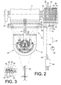
- Fig. 1
- eine Seitenansicht einer Arbeitsstelle einer Kreuzspulen herstellenden Textilmaschine,
- Fig. 2
- eine Vorderansicht auf die Spulvorrichtung der in Figur 1 angedeuteten Arbeitsstelle, mit einer in ein erfindungsgemäßes Lagergehäuse eines Spulenrahmens intergrierten Antriebseinrichtung, teilweise im Schnitt,
- Fig. 3
- die Einzelheit III der Figur 2, im Schnitt.
Von dem bekannten Spulen- und Hülsentransportsystem 3 sind in Figur 1 lediglich die Kopszuführstrecke 4, die reversierend antreibbare Speicherstrecke 5, eine der zu den Spulstellen 2 führenden Quertransportstrecken 6 sowie die Hülsenrückführstrecke 7 dargestellt.
Der Antrieb der Kreuzspule 11 erfolgt über eine drehzahlregelbare Antriebseinrichtung 27. Diese vorzugsweise als elektronisch kommutierbarer Gleichstrommotor 45 ausgebildete Antriebseinrichtung 27 ist, wie aus Figur 2 ersichtlich, in ein Lagergehäuse 23 des Spulenrahmens 18 integriert und über Stromleitungen 51, 52 an eine (nicht dargestellte) Gleichstromquelle angeschlossen.
Zur Changierung des Fadens 30 während des Spulprozesses ist eine Fadenchangiereinrichtung 28 vorgesehen. Eine solche in Figur 2 angedeutete Changiereinrichtung ist beispielsweise in der DE 198 58 548 A1 ausführlich beschrieben.
Derartige Spulstellen weisen des weiteren eine spulstelleneigene Steuereinrichtung, einen sogenannten Spulstellenrechner 39 auf, der die Arbeitsabläufe der vorbeschriebenen Einrichtungen koordiniert und der über einen Maschinenbus 40 an eine Zentralsteuereinheit 37 des Kreuzspulautomaten 1 angeschlossen ist.
Das Lagergehäuse 23 weist dabei, wie in Figur 3 im Detail dargestellt, eine Vielzahl von Kühlrippen 33 auf, die an ihrem Außenumfang jeweils mit Kuppen 36 versehen sind.
Der gegenseitige Abstand a der Kühlrippen 33, die ihrerseits aus einem gut wärmeleitfähigen Material, zum Beispiel Stahl oder Aluminium bestehen, ist so gewählt, daß eine unabsichtliche Berührung der den Kühlrippengrund 38 bildenden, unbeschichteten Kühlrippenflächen ausgeschlossen ist.
Des weiteren kann im Bereich des Lagergehäuses 23 eine vorzugsweise pneumatisch arbeitende Zusatzkühleinrichtung 43 angeordnet sein, die über ein Wegeventil 44 sowie eine Pneumatikleitung 47 an eine Überdruckquelle 48 angeschlossen ist. Das elektromagnetisch schaltbare Wegeventil 44 ist dabei seinerseits über eine Signalleitung 46 mit dem Spulstellenrechner 39 verbunden und bei Bedarf von diesem definiert ansteuerbar.
Die auf den Kühlrippen 33 angeordneten, wenig wärmeleitfähigen Kuppen 36 verhindern dabei, daß sich das Bedienpersonal an den Kühlrippen 33, die insbesondere in den unbeschichteten Kühlrippenbereichen relativ heiß werden, verbrennen kann.
Claims (6)
- Lagergehäuse für eine in einen Spulenrahmen integrierte Antriebseinrichtung einer Kreuzspulen herstellenden Textilmaschine, wobei die Antriebseinrichtung zum Abbremsen der Kreuzspule mit einem gegensinnig zum Nennstrom gerichteten Bremsstrom beaufschlagbar ist,
dadurch gekennzeichnet, daß das Lagergehäuse (23) eine Vielzahl von Kühlrippen (33) aufweist, deren Außenbereich mit einem Material beschichtet ist, das eine niedrige Wärmeleitzahl (λ) aufweist. - Lagergehäuse nach Anspruch 1, dadurch gekennzeichnet, daß die Kühlrippen (33) des Lagergehäuses (23) Kuppen (36) aufweisen, die aus einem Thermoplast, vorzugsweise einem Polyamid, bestehen.
- Lagergehäuse nach Anspruch 1 und 2, dadurch gekennzeichnet, daß der gegenseitige Abstand (a) der Kühlrippen (33) so gewählt ist, daß eine unabsichtliche Berührung des unbeschichteten Kühlrippengrundes (38) ausgeschlossen ist.
- Lagergehäuse nach einem der vorherigen Ansprüche, dadurch gekennzeichnet, daß im Bereich des Lagergehäuses (23) eine Sensoreinrichtung (41) angeordnet ist, die dessen Temperatur überwacht.
- Lagergehäuse nach einem der vorherigen Ansprüche, dadurch gekennzeichnet, daß eine Zusatzkühleinrichtung (43) vorgesehen ist, die bei Bedarf eine zusätzliche Kühlung des Lagergehäuses (23) ermöglicht.
- Lagergehäuse nach Anspruch 4 oder 5, dadurch gekennzeichnet, daß die Sensoreinrichtung (41) an einen Spulstellenrechner (39) angeschlossen ist, der nach Maßgabe entsprechender Signale der Sensoreinrichtung temporär ein Ventil (44) ansteuert, das die pneumatisch arbeitende Zusatzkühleinrichtung (43) aktiviert.
Applications Claiming Priority (2)
| Application Number | Priority Date | Filing Date | Title |
|---|---|---|---|
| DE10040109 | 2000-08-17 | ||
| DE10040109A DE10040109A1 (de) | 2000-08-17 | 2000-08-17 | Lagergehäuse für eine Antriebseinrichtung einer Kreuzspulen herstellenden Textilmaschine |
Publications (3)
| Publication Number | Publication Date |
|---|---|
| EP1184322A2 true EP1184322A2 (de) | 2002-03-06 |
| EP1184322A3 EP1184322A3 (de) | 2002-06-26 |
| EP1184322B1 EP1184322B1 (de) | 2004-04-21 |
Family
ID=7652672
Family Applications (1)
| Application Number | Title | Priority Date | Filing Date |
|---|---|---|---|
| EP01112108A Expired - Lifetime EP1184322B1 (de) | 2000-08-17 | 2001-05-17 | Lagergehäuse für eine Antriebseinrichtung einer Kreuzspulen herstellenden Textilmaschine |
Country Status (6)
| Country | Link |
|---|---|
| US (1) | US6566773B2 (de) |
| EP (1) | EP1184322B1 (de) |
| JP (1) | JP4393023B2 (de) |
| CN (1) | CN1339398A (de) |
| AT (1) | ATE264806T1 (de) |
| DE (2) | DE10040109A1 (de) |
Families Citing this family (11)
| Publication number | Priority date | Publication date | Assignee | Title |
|---|---|---|---|---|
| DE102005001094A1 (de) * | 2005-01-08 | 2006-07-20 | Saurer Gmbh & Co. Kg | Verfahren und Vorrichtung zum Betreiben einer Arbeitsstelle einer Kreuzspulen herstellenden Textilmaschine |
| US7582634B2 (en) * | 2005-02-18 | 2009-09-01 | Wyeth | 7-substituted imidazo[4,5-c]pyridine antagonists of gonadotropin releasing hormone receptor |
| DE102006050140A1 (de) * | 2006-10-25 | 2008-04-30 | Oerlikon Textile Gmbh & Co. Kg | Spulenbremse für eine Spulvorrichtung einer Kreuzspulen herstellenden Textilmaschine |
| DE102006053045A1 (de) * | 2006-11-10 | 2008-05-15 | Oerlikon Textile Gmbh & Co. Kg | Arbeitsstelle einer Kreuzspulen herstellenden Textilmaschine |
| JP5545593B2 (ja) * | 2010-03-17 | 2014-07-09 | 村田機械株式会社 | 糸巻取機 |
| JP5557002B2 (ja) * | 2010-03-17 | 2014-07-23 | 村田機械株式会社 | 糸巻取機 |
| KR101267228B1 (ko) * | 2013-03-14 | 2013-05-27 | 허옥동 | 송풍기용 일체형 베어링하우징 |
| CH709698A1 (de) * | 2014-05-27 | 2015-11-30 | Rieter Ag Maschf | Changierelement für eine Spinnmaschine sowie damit ausgestattete Spinnmaschine. |
| CN105565070B (zh) * | 2014-10-14 | 2020-01-03 | 舍弗勒技术股份两合公司 | 导纱器和纱线卷绕机 |
| US10315894B2 (en) * | 2017-01-30 | 2019-06-11 | Cameron Anderson | Winch fairlead guide |
| DE102023125176A1 (de) * | 2023-09-18 | 2025-03-20 | Maschinenfabrik Rieter Ag | Verfahren zum Betreiben einer Arbeitsstelle, Arbeitsstelle sowie Textilmaschine |
Family Cites Families (14)
| Publication number | Priority date | Publication date | Assignee | Title |
|---|---|---|---|---|
| DE214114C (de) | ||||
| DE2106898A1 (de) | 1971-02-13 | 1972-08-24 | Siemens Ag | Spinnturbine mit einem drehzahlgeregelten, abbremsbaren elektrischen Antriebsmotor |
| US3972171A (en) * | 1971-06-21 | 1976-08-03 | Schubert & Salzer Maschinenfabrik Aktiengesellschaft | Housing construction for open end spinning machines |
| CS187697B1 (en) | 1976-07-06 | 1979-02-28 | Milan Chrtek | Method of and apparatus for cooling spinning units of open-end spinning machines |
| FR2508499A1 (fr) * | 1981-06-29 | 1982-12-31 | Asa Sa | Broche de retordage entrainee par un moteur electrique individuel |
| DE3326405C2 (de) * | 1983-07-22 | 1986-04-10 | Schubert & Salzer Maschinenfabrik Ag, 8070 Ingolstadt | Offenend-Rotorspinnvorrichtung |
| JPH05111211A (ja) * | 1991-10-18 | 1993-04-30 | Mitsubishi Electric Corp | 電動機 |
| DE59706488D1 (de) * | 1996-11-27 | 2002-04-04 | Barmag Barmer Maschf | Aufspulmaschine |
| JPH10194591A (ja) * | 1996-12-27 | 1998-07-28 | Murata Mach Ltd | 紡糸巻取機の制御盤の冷却装置 |
| JPH1189165A (ja) * | 1997-09-10 | 1999-03-30 | Nippon Electric Ind Co Ltd | Srモータの放熱構造 |
| EP0972867B1 (de) * | 1998-07-14 | 2004-03-17 | Murata Kikai Kabushiki Kaisha | Mehrfach-Zwirnmaschine mit Einzelspindelantrieb |
| DE19836701A1 (de) | 1998-08-13 | 2000-02-17 | Schlafhorst & Co W | Verfahren zum Stillsetzen eines elektrischen Antriebsmotors und Bremsschaltung |
| DE19858548A1 (de) | 1998-12-18 | 2000-06-21 | Schlafhorst & Co W | Fadenführer zum traversierenden Zuführen eines Fadens zu einer rotierend angetriebenen Auflaufspule |
| DE19908093A1 (de) * | 1999-02-25 | 2000-08-31 | Schlafhorst & Co W | Spulvorrichtung für eine Kreuzspulen herstellende Textilmaschine |
-
2000
- 2000-08-17 DE DE10040109A patent/DE10040109A1/de not_active Withdrawn
-
2001
- 2001-05-17 DE DE50102035T patent/DE50102035D1/de not_active Expired - Fee Related
- 2001-05-17 EP EP01112108A patent/EP1184322B1/de not_active Expired - Lifetime
- 2001-05-17 AT AT01112108T patent/ATE264806T1/de not_active IP Right Cessation
- 2001-08-14 JP JP2001246271A patent/JP4393023B2/ja not_active Expired - Fee Related
- 2001-08-17 US US09/932,176 patent/US6566773B2/en not_active Expired - Fee Related
- 2001-08-17 CN CN01133955A patent/CN1339398A/zh active Pending
Also Published As
| Publication number | Publication date |
|---|---|
| JP2002114442A (ja) | 2002-04-16 |
| US6566773B2 (en) | 2003-05-20 |
| DE10040109A1 (de) | 2002-02-28 |
| US20020021851A1 (en) | 2002-02-21 |
| DE50102035D1 (de) | 2004-05-27 |
| JP4393023B2 (ja) | 2010-01-06 |
| EP1184322B1 (de) | 2004-04-21 |
| EP1184322A3 (de) | 2002-06-26 |
| CN1339398A (zh) | 2002-03-13 |
| ATE264806T1 (de) | 2004-05-15 |
Similar Documents
| Publication | Publication Date | Title |
|---|---|---|
| EP2957532B1 (de) | Arbeitsstelle einer kreuzspulen herstellenden textilmaschine | |
| DE102007053467B4 (de) | Verfahren und Vorrichtung zum Betreiben einer Offenend-Rotorspinnmaschine | |
| EP2657380B1 (de) | Verfahren und Vorrichtung zum Betreiben von Arbeitsstellen einer Offenend-Rotorspinnmaschine | |
| EP1184322B1 (de) | Lagergehäuse für eine Antriebseinrichtung einer Kreuzspulen herstellenden Textilmaschine | |
| EP1184320B1 (de) | Spulvorrichtung für eine Kreuzspulen herstellende Textilmaschine | |
| EP0846640B1 (de) | Kreuzspulen herstellende Textilmaschine | |
| DE102009004615A1 (de) | Verfahren zum Betreiben einer Spulvorrichtung und Spulvorrichtung einer Auflaufspulen herstellenden Textilmaschine | |
| EP2066577B1 (de) | Saugdüse für eine arbeitsstelle einer kreuzspulen herstellenden textilmaschine | |
| DE102017114707A1 (de) | Fadenspleißvorrichtung zum pneumatischen Verbinden von Fadenenden | |
| DE19908093A1 (de) | Spulvorrichtung für eine Kreuzspulen herstellende Textilmaschine | |
| DE102007036696A1 (de) | Kreuzspulenwechsler | |
| DE102010021153A1 (de) | Bedienaggregat | |
| EP2097346B1 (de) | Spulenbremse für eine spulvorrichtung einer kreuzspulen herstellenden textilmaschine | |
| DE102007048721A1 (de) | Serviceaggregat | |
| EP1184321A2 (de) | Spulenrahmen für eine Kreuzspulen herstellende Textilmaschine | |
| DE102007035430B4 (de) | Spulvorrichtung für eine Arbeitsstelle einer Offenend-Spinnmaschine | |
| EP1917204B1 (de) | Spulstelle einer kreuzspule herstellenden textilmaschine | |
| DE102017102438A1 (de) | Fadenspleißvorrichtung für eine Arbeitsstelle einer Kreuzspulen herstellenden Textilmaschine | |
| DE10007949A1 (de) | Spulenrahmen für eine Textilmaschine | |
| DE102016117613A1 (de) | Spulenbremse für eine Spulvorrichtung einer Auflaufspulen herstellenden Textilmaschine | |
| EP0468390B1 (de) | Verfahren und Vorrichtung zur Bildung einer Fadenendreserve-wicklung auf Spulen an einer Textilmaschine | |
| DE102006053045A1 (de) | Arbeitsstelle einer Kreuzspulen herstellenden Textilmaschine | |
| DE102020108339A1 (de) | Kreuzspulen herstellende Textilmaschine bzw. Verfahren zum Betreiben einer Kreuzspulen herstellenden Textilmaschine | |
| DE10336683A1 (de) | Spulstelle für eine Kreuzspulen herstellende Textilmaschine | |
| EP3321222A1 (de) | Fadenumlenkrolle für einen im bereich des fadenchangierdreieckes einer arbeitsstelle einer kreuzspulen herstellenden textilmaschine angeordneten mechanischen fadenspeicher |
Legal Events
| Date | Code | Title | Description |
|---|---|---|---|
| PUAI | Public reference made under article 153(3) epc to a published international application that has entered the european phase |
Free format text: ORIGINAL CODE: 0009012 |
|
| AK | Designated contracting states |
Kind code of ref document: A2 Designated state(s): AT BE CH CY DE DK ES FI FR GB GR IE IT LI LU MC NL PT SE TR |
|
| AX | Request for extension of the european patent |
Free format text: AL;LT;LV;MK;RO;SI |
|
| PUAL | Search report despatched |
Free format text: ORIGINAL CODE: 0009013 |
|
| AK | Designated contracting states |
Kind code of ref document: A3 Designated state(s): AT BE CH CY DE DK ES FI FR GB GR IE IT LI LU MC NL PT SE TR |
|
| AX | Request for extension of the european patent |
Free format text: AL;LT;LV;MK;RO;SI |
|
| 17P | Request for examination filed |
Effective date: 20021227 |
|
| AKX | Designation fees paid |
Designated state(s): AT CH DE IT LI TR |
|
| GRAP | Despatch of communication of intention to grant a patent |
Free format text: ORIGINAL CODE: EPIDOSNIGR1 |
|
| RAP1 | Party data changed (applicant data changed or rights of an application transferred) |
Owner name: SAURER GMBH & CO. KG |
|
| GRAS | Grant fee paid |
Free format text: ORIGINAL CODE: EPIDOSNIGR3 |
|
| GRAA | (expected) grant |
Free format text: ORIGINAL CODE: 0009210 |
|
| AK | Designated contracting states |
Kind code of ref document: B1 Designated state(s): AT CH DE IT LI TR |
|
| PG25 | Lapsed in a contracting state [announced via postgrant information from national office to epo] |
Ref country code: TR Free format text: LAPSE BECAUSE OF FAILURE TO SUBMIT A TRANSLATION OF THE DESCRIPTION OR TO PAY THE FEE WITHIN THE PRESCRIBED TIME-LIMIT Effective date: 20040421 Ref country code: IT Free format text: LAPSE BECAUSE OF FAILURE TO SUBMIT A TRANSLATION OF THE DESCRIPTION OR TO PAY THE FEE WITHIN THE PRESCRIBED TIME-LIMIT;WARNING: LAPSES OF ITALIAN PATENTS WITH EFFECTIVE DATE BEFORE 2007 MAY HAVE OCCURRED AT ANY TIME BEFORE 2007. THE CORRECT EFFECTIVE DATE MAY BE DIFFERENT FROM THE ONE RECORDED. Effective date: 20040421 |
|
| REG | Reference to a national code |
Ref country code: CH Ref legal event code: EP |
|
| PG25 | Lapsed in a contracting state [announced via postgrant information from national office to epo] |
Ref country code: AT Free format text: LAPSE BECAUSE OF NON-PAYMENT OF DUE FEES Effective date: 20040517 |
|
| REG | Reference to a national code |
Ref country code: IE Ref legal event code: FG4D Free format text: GERMAN |
|
| REF | Corresponds to: |
Ref document number: 50102035 Country of ref document: DE Date of ref document: 20040527 Kind code of ref document: P |
|
| PG25 | Lapsed in a contracting state [announced via postgrant information from national office to epo] |
Ref country code: DE Free format text: LAPSE BECAUSE OF NON-PAYMENT OF DUE FEES Effective date: 20041201 |
|
| REG | Reference to a national code |
Ref country code: IE Ref legal event code: FD4D |
|
| PLBE | No opposition filed within time limit |
Free format text: ORIGINAL CODE: 0009261 |
|
| STAA | Information on the status of an ep patent application or granted ep patent |
Free format text: STATUS: NO OPPOSITION FILED WITHIN TIME LIMIT |
|
| 26N | No opposition filed |
Effective date: 20050124 |
|
| PG25 | Lapsed in a contracting state [announced via postgrant information from national office to epo] |
Ref country code: CH Free format text: LAPSE BECAUSE OF NON-PAYMENT OF DUE FEES Effective date: 20050531 Ref country code: LI Free format text: LAPSE BECAUSE OF NON-PAYMENT OF DUE FEES Effective date: 20050531 |
|
| REG | Reference to a national code |
Ref country code: CH Ref legal event code: PL |