EP1183934B1 - Gerät zur Rasen-, Garten- bzw. Grundstückspflege - Google Patents
Gerät zur Rasen-, Garten- bzw. Grundstückspflege Download PDFInfo
- Publication number
- EP1183934B1 EP1183934B1 EP01120123A EP01120123A EP1183934B1 EP 1183934 B1 EP1183934 B1 EP 1183934B1 EP 01120123 A EP01120123 A EP 01120123A EP 01120123 A EP01120123 A EP 01120123A EP 1183934 B1 EP1183934 B1 EP 1183934B1
- Authority
- EP
- European Patent Office
- Prior art keywords
- implement according
- guide rail
- housing
- guide handle
- locking lever
- Prior art date
- Legal status (The legal status is an assumption and is not a legal conclusion. Google has not performed a legal analysis and makes no representation as to the accuracy of the status listed.)
- Expired - Lifetime
Links
- 238000012423 maintenance Methods 0.000 title description 11
- 230000001419 dependent effect Effects 0.000 claims 1
- 235000003332 Ilex aquifolium Nutrition 0.000 description 7
- 241000209027 Ilex aquifolium Species 0.000 description 7
- 230000000694 effects Effects 0.000 description 7
- 241000196324 Embryophyta Species 0.000 description 6
- 238000002485 combustion reaction Methods 0.000 description 5
- 239000000463 material Substances 0.000 description 4
- 238000003860 storage Methods 0.000 description 4
- 230000009471 action Effects 0.000 description 3
- 238000004140 cleaning Methods 0.000 description 3
- 238000013461 design Methods 0.000 description 3
- 230000002349 favourable effect Effects 0.000 description 3
- 239000000446 fuel Substances 0.000 description 3
- 238000012546 transfer Methods 0.000 description 3
- 230000005540 biological transmission Effects 0.000 description 2
- 230000008878 coupling Effects 0.000 description 2
- 238000010168 coupling process Methods 0.000 description 2
- 238000005859 coupling reaction Methods 0.000 description 2
- 238000004519 manufacturing process Methods 0.000 description 2
- 238000004091 panning Methods 0.000 description 2
- 239000004033 plastic Substances 0.000 description 2
- 238000005096 rolling process Methods 0.000 description 2
- 230000008719 thickening Effects 0.000 description 2
- 244000025254 Cannabis sativa Species 0.000 description 1
- 241000282414 Homo sapiens Species 0.000 description 1
- 125000002066 L-histidyl group Chemical group [H]N1C([H])=NC(C([H])([H])[C@](C(=O)[*])([H])N([H])[H])=C1[H] 0.000 description 1
- 241001494496 Leersia Species 0.000 description 1
- 241001417527 Pempheridae Species 0.000 description 1
- 230000008859 change Effects 0.000 description 1
- 239000003795 chemical substances by application Substances 0.000 description 1
- 238000005352 clarification Methods 0.000 description 1
- 238000004891 communication Methods 0.000 description 1
- 238000009264 composting Methods 0.000 description 1
- 238000011109 contamination Methods 0.000 description 1
- 239000002826 coolant Substances 0.000 description 1
- 230000003993 interaction Effects 0.000 description 1
- 239000000314 lubricant Substances 0.000 description 1
- 239000002184 metal Substances 0.000 description 1
- 230000008635 plant growth Effects 0.000 description 1
- 238000003825 pressing Methods 0.000 description 1
- 238000009420 retrofitting Methods 0.000 description 1
- 238000010008 shearing Methods 0.000 description 1
- 239000000758 substrate Substances 0.000 description 1
- 239000000725 suspension Substances 0.000 description 1
- 238000010408 sweeping Methods 0.000 description 1
- 238000012360 testing method Methods 0.000 description 1
- 239000004753 textile Substances 0.000 description 1
- 239000002699 waste material Substances 0.000 description 1
Images







Classifications
-
- A—HUMAN NECESSITIES
- A01—AGRICULTURE; FORESTRY; ANIMAL HUSBANDRY; HUNTING; TRAPPING; FISHING
- A01D—HARVESTING; MOWING
- A01D34/00—Mowers; Mowing apparatus of harvesters
- A01D34/01—Mowers; Mowing apparatus of harvesters characterised by features relating to the type of cutting apparatus
- A01D34/412—Mowers; Mowing apparatus of harvesters characterised by features relating to the type of cutting apparatus having rotating cutters
- A01D34/63—Mowers; Mowing apparatus of harvesters characterised by features relating to the type of cutting apparatus having rotating cutters having cutters rotating about a vertical axis
- A01D34/67—Mowers; Mowing apparatus of harvesters characterised by features relating to the type of cutting apparatus having rotating cutters having cutters rotating about a vertical axis hand-guided by a walking operator
- A01D34/68—Mowers; Mowing apparatus of harvesters characterised by features relating to the type of cutting apparatus having rotating cutters having cutters rotating about a vertical axis hand-guided by a walking operator with motor driven cutters or wheels
- A01D34/6806—Driving mechanisms
-
- A—HUMAN NECESSITIES
- A01—AGRICULTURE; FORESTRY; ANIMAL HUSBANDRY; HUNTING; TRAPPING; FISHING
- A01D—HARVESTING; MOWING
- A01D34/00—Mowers; Mowing apparatus of harvesters
- A01D34/01—Mowers; Mowing apparatus of harvesters characterised by features relating to the type of cutting apparatus
- A01D34/412—Mowers; Mowing apparatus of harvesters characterised by features relating to the type of cutting apparatus having rotating cutters
- A01D34/63—Mowers; Mowing apparatus of harvesters characterised by features relating to the type of cutting apparatus having rotating cutters having cutters rotating about a vertical axis
- A01D34/67—Mowers; Mowing apparatus of harvesters characterised by features relating to the type of cutting apparatus having rotating cutters having cutters rotating about a vertical axis hand-guided by a walking operator
- A01D34/68—Mowers; Mowing apparatus of harvesters characterised by features relating to the type of cutting apparatus having rotating cutters having cutters rotating about a vertical axis hand-guided by a walking operator with motor driven cutters or wheels
- A01D2034/6843—Control levers on the handle of the mower
-
- A—HUMAN NECESSITIES
- A01—AGRICULTURE; FORESTRY; ANIMAL HUSBANDRY; HUNTING; TRAPPING; FISHING
- A01D—HARVESTING; MOWING
- A01D2101/00—Lawn-mowers
-
- A—HUMAN NECESSITIES
- A01—AGRICULTURE; FORESTRY; ANIMAL HUSBANDRY; HUNTING; TRAPPING; FISHING
- A01D—HARVESTING; MOWING
- A01D34/00—Mowers; Mowing apparatus of harvesters
- A01D34/01—Mowers; Mowing apparatus of harvesters characterised by features relating to the type of cutting apparatus
- A01D34/412—Mowers; Mowing apparatus of harvesters characterised by features relating to the type of cutting apparatus having rotating cutters
- A01D34/63—Mowers; Mowing apparatus of harvesters characterised by features relating to the type of cutting apparatus having rotating cutters having cutters rotating about a vertical axis
Definitions
- the invention relates to a device preferably for lawn, Garden or property maintenance with a housing and a movable with the housing connectable guide rail and with a drive, at least one working unit and a Safety device.
- Hand-held or hand-pushed lawnmowers often show a guide rail on the lawn mower or a Housing is arranged in a rear area.
- Such Guide rails can be provided movable, so that they at Not in use or placed in a position for transport can be in which the lawnmower is a lesser Have space requirements.
- EP-A1-0 903 074 shows a lawnmower with a stand up Wheels supporting housing and a fishing bag attached to the Housing in the region of an ejection opening below a Guide Holms is provided.
- the guide rail is with the Housing pivotally connected, so that he from the collecting bag or the ejection opening away, relative to the housing forward can be pivoted.
- the lawnmower has one Safety device to ensure that the Cover with rotating mowing blades always by one Cover flap is closed or that the mower blade at opened cover can not be driven.
- FR-A-2 237 566 shows a lawnmower with a pivotally connected to a housing guide rail and a device by which the speed of a drive of the mower due to the position of the guide rail can be controlled.
- FR-A-2 780 375 describes a device in the nature of a Lawn mower with a guide rail, based on the device can be folded forward to provide access to one arranged in a rear area of the device To allow collection container.
- US-A-4,753,062 discloses a lawn mower having a pivotally connected to the lawnmower guide rail as well having a collection container.
- the guide rail is over Rope connected to a lid of the collecting container such that the guide rail over the lid to the sump and thus can be secured in its operating position.
- the rope Switch provided, which is only then closed and a Operation of a drive of the lawnmower permits, if the Guide rail secured over the rope in its operating position is.
- the guide rail at least in one Position, which is preferably his Operating position, be set so that a unintentional pivoting is counteracted, which to could cause a hazard to an operator, as the Device can no longer be guided safely or a specific one Safety distance between the device and the operator could not be met.
- a device for lawn, Garden or property maintenance can be a hand-pushed or a hand-held device like a Mower, for example, in the manner of a lawn mower, such as a reel mower or a sickle mower. But it is also conceivable that such a device a leaf collector or -reäum réelle, a snow removal device, a sweeper or similar Device is.
- the locking of the guide rail depends on the position of a safety device in which it is For example, a dead man's circuit or an emergency stop switch, an engine brake bracket or an engine brake device or even another lock for another Component, in particular for a safety-relevant component, such as a cover flap for an ejection opening etc., that can act on a drive of the device has the effect that it can only be operated if the Safety device in a certain position or a certain state is located.
- the Verrieglung can also with a foot pedal or a pedal interact or the Safety device can as such or such be educated.
- the locking device acts directly or indirectly with the safety device, for example, such together that means are provided, the position or the Condition of the safety device to the locking device transmit or transmit, so that their position can be influenced.
- This can be done, for example, via sensors or electrical equipment or pneumatic, hydraulic but preferably via mechanical means, such as pull-push cables.
- means can also be equipped with a motor brake, the allows operation of the drive of the device or prevents, be connected.
- the engine brake can also with independent of the locking means with the Collaborate safety device.
- a motor brake cooperating safety device can For example, as stated above, to a Engine braking device or an engine brake bracket or lever act.
- the engine brake for example, via electrical, pneumatic, hydraulic or mechanical means, such as a pull-push cable, with such is connected to the guide rail or cooperates with this, that by this, depending on the position of the Guide Holms closed or opened.
- the Safety device can continue on such example act the drive that this depending on the position the safety device is shorted, so that a Operation only with a preferably operated Safety device is enabled.
- a coupling with the guide rail effective is connected, so that, for example, an operation of or several working units, such as knives, Kehr wornen etc. or even of wheels is only possible when the guide rail in a certain position, the preferably corresponds to its operating position is located. This is particularly favorable for devices where already one Coupling is provided for connecting work equipment.
- the locking device may have a stop means, its position, for example, by the means or a train-pressure cable, can be influenced, preferably directly or can interact indirectly with the safety device.
- the pull-push cable can be placed on the preferably pivotally provided on the housing Act stop means and determine the pivot position that it the guide rail directly or over the Locking lever or provided on this attacks sets.
- lever, linkage or electrical for example, having an electromagnet, Provide locking devices.
- the Locking device instead of the engine brake bracket with one (or more) further or other (safety) Handle (s), lever (s) or switch (s) cooperate
- train-pressure cable can be directly or indirectly acting on an engine brake, so that the operation of the drive allows or can be prevented and a simple functional connection with the locking device for Is made available.
- Train-pressure cables are connected to devices and especially on equipment for lawn, garden and Land maintenance often used, for example, one To connect the engine brake lever to an engine brake.
- the position of the sling can be controlled by mechanical means, such as a linkage, or by electrical, pneumatic or hydraulic means are determined.
- a train-pressure cable acts on the Slings. This can be done by the internal wire or the soul of the train-pressure cable with the Slings is connected and this adjusted, or in that the outer shell is connected to the stop means and the internal wire is otherwise connected and For example, an actuation or adjustment of another Component allows.
- the pull-push cable can be so interact with the stop means that a change in the Position of the engine brake is only possible if the Slings located in a predetermined position that it preferably occupies when the guide rail in his Operating position in which he pivoted backwards is. In this way it can be achieved that the engine brake only be opened and thus the drive allowed or can be operated when the guide rail is secure in operating position, and no danger an operator or other persons etc. by a unintentional starting or uncontrolled operation of the Drive or the device can come.
- the attachment may be a collection container for example, to receive cut plant material like grass, leaves or other waste, as they are a mowing, clearing or collecting device incurred. He can, too a baffle that is cut or collected Material deposits in a certain direction, or one Cover flap be an opening, for example, in the art a maintenance opening, preferably during operation of the Device closes, so that an operator, etc. not unintentionally with a powered work unit like Mower blades or a sweeping device can come into contact.
- Does the fixing device a preferably with the Housing pivotally connectable locking lever on, so can this can be pivoted to lock the attachment and For example, in a recess of the attachment or in a Eyelet or similar engage the attachment, so that they are based on the housing is fixed. But it is also conceivable that the Locking in another way, for example by means of a Electromagnet or by means of a sliding bolt o.ä. depending on the position of the guide spar done.
- the stop means directly with the Guide rail or a stop on the guide rail interacts. But it is particularly favorable when the Slings or with this cooperating stop elements is provided on the locking lever / are there whose position depends on the position of the guide rail and the locking lever preferably already between the Guide rail and the housing or the device or in general the guide rail is disposed adjacent.
- the stop means at least partially in the manner of a collar element and / or be executed hook-like, so that the stop element at least partially can be included or different stop surfaces are provided.
- the locking lever may take the form of, for example rectangular bolt executed in a corresponding trained recess can intervene. If the Locking lever is designed in the manner of a disc, preferably between the housing and the guide rail is arranged, this leads to a simple production. The disc-like design acts to jam the Locking lever during a pivoting movement, because the disc surface on the guide rail or on the housing or slide along other components during pivoting can.
- the hook-like Section but adapted thereto, a holding device for example, in the manner of a support pin, attached to the Attachment, on a carrying handle or a support frame, etc. of the Attachment is provided to accommodate or overlap to to secure the attachment to the device.
- the locking lever and the guide rail can also have a common pivot axis; are the swivel axes but provided spaced, so there is a geometry that an overlapping of the locking lever on the attachment or favored over the suspension means.
- the attachment or the Holding device are usually of the pivot axis of the Guide Holms spaced to the rear or to the rear and above arranged, which is determined by the distance of the pivot axes can be compensated.
- the Position of the guide rail relative to the device by means of a Detected and via electrical means, for example in the manner of lines, to the fixing device is passed on.
- the position of Lock lever are also affected or a Electromagnet are acted upon in such a way that he the attachment on the device.
- the locking lever or on the locking lever provided component for example in the manner of a projecting pin, in a recess of the guide rail, so that pivoting of the guide rail in one Pivoting movement of the locking lever results.
- the Guide rail or a connected or connectable with this Component in a recess or in an eyelet, etc. on the Attachment or the locking lever engages.
- the recess is preferably in the manner of a Long hole executed.
- a preferably ramp-like support element provided, this can with the fixing device such cooperate, that the attachment by the support member, the preferably in a rear region of the housing is arranged, recorded, and the fixing device or the locking lever the attachment on the Specify recording medium.
- the ramp-like execution the is preferably carried out to increase in reverse, causes that the attachment by its own weight in the direction of the Housing or the device is charged, what an unwanted Loosening of the attachment counteracts.
- the ramp can be smooth be executed or have one or more wells, around the attachment in one or more fixed positions to be able to record or to an uncontrolled sliding of the Counteracting fixture on the receiving means. In simple shape, the surface of the ramp can wavy this be executed.
- High user safety is achieved when the Locking device with a drive of the device such cooperates to prevent the operation of the drive, if the guide rail is not in a specific position, which is preferably its operating position, located. This ensures that the drive only tempered or operated, if by the backward pivoted guide rail is ensured that between the device or its tools such as mowing blades or Keher coupleden a certain safety distance is present, so that no inadvertent contact of the Operator with the work equipment can occur.
- the Locking device for example via a train-pressure cable or also electrically, hydraulically, pneumatically or via Linkage or lever interacts with an engine brake
- the For example may be formed such that they Has brake means in the form of brake shoes or brushes, the on a flywheel or a flywheel of an engine or the Drive can act.
- the braking means are preferably spring-loaded, so that they are in the unactuated state on the pole wheel or flywheel, whereby an operation of the drive is prevented. It can also be provided that the drive shorted when the guide rail is not in the intended operating position is located, so that the operation of the Drive is again prevented. Also a combination of mentioned agent is advantageously used.
- Devices in particular devices for lawn, garden or Property maintenance often requires maintenance or maintenance Cleaning a bottom of the housing or from Working units, such as mowing knives, etc., below the Housing are arranged.
- Working units such as mowing knives, etc.
- the device can be tilted in a known manner.
- a tilt to the side so that the device rests on a side surface, as known at the back Devices a guide rail and other attachments, such as For example, a cover, etc. are arranged.
- the guide rail can be brought into a position in which the device in a pivoted backward state by means of of the guide rail can rest on a substrate, so is tilting the device backwards possible without the Guide rail opposes such and it is one safe positioning of the device by supporting it over the Guide rail given.
- the position of the guide rail around a relative to the housing swung forward forward operating position.
- the Guide rail is moved. It can be provided that a Operation of the unit or work unit in this position is possible, for example, to be able to test them; Preferably, however, an operation is prevented to hazards For example, to counteract an operator.
- the guide rail can in the out-of-service position for example, abut against a stop or otherwise so be prevented from moving, so that he Can support weight of the housing.
- the stability or Safety can be further increased if the guide rail in This position is administratbar, so that a movement is not is possible and the guide rail a permanent support guaranteed.
- the guide rail for example, in known manner by means of a bolt or pin on the device or its housing are set, in which this by Recesses in the guide rail and the housing is inserted through and for example by a Circlip is secured against falling out.
- bars, lugs etc. conceivable.
- a mower or a device 10 in the manner of a hand-held or also hand-pushed lawnmower shown in an operating position becomes.
- the device 10 has a housing 12 which extends over two front and two rear wheels 14 on the ground supported.
- On the housing 12 is an only hinted way illustrated drive 15, for example in the manner of a Internal combustion engine or an electric drive provided to one or more below the housing 12th mounted mower blades or work units, for example in the kind of sickle knives or also of spindle knives, in Rotation to cut grass or plant growth.
- the housing 12 has in a relative to the usual Operating direction of the device 10 rear area 16 a only suggestively illustrated ejection opening 18, on the cut plant sections leave the housing 12 can.
- a Guide bar 20 about an axis A, a locking lever 22 to an axis B at least upwardly spaced from the axis A. and a cover flap 24 around a not shown, but preferably further backward arranged axis pivotally appropriate.
- a collecting container 26 releasably attached to the device 10 and the housing 12 is provided so that in this by the Ejection port 18 discharged plant sections collected can be to later disposal or even Composting to be supplied.
- the guide rail 20 is designed as a rod and points in a the housing 12 and the axis A facing a region Recess or a slot 44, in which a on the Locking lever 22 provided pin 46 in the art can intervene that a joint movement of the guide rail 20 and the locking lever 22 is effected.
- the pull-push cable 32 has a shell 34 and a soul 36 in the manner of one in the shell 34 slidably arranged wire on.
- the train-pressure cable 32 is over its sheath 34 in one of the security device 28 facing region of the guide rail 20 with this immovably connected and acts on his soul 36 with the Safety device 28 together.
- the pull-push cable works 32 with the locking lever 22 and more Components together, which are discussed in more detail below shall be.
- the braking device 30 is as one with the Guide rail 20 connected lever 38 executed, the extends radially beyond the axis A addition and together with the Guide rail 20 is pivotable. At its axis A remote end portion 40 he is with a brake pad 42, the can act on the wheels 14, provided.
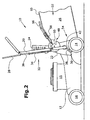
- the device 10 is in an inoperative position shown in the guide rail 20 relative to the housing 12th forward and thus also with the guide rail 20 on the Slot 44 and the pin 46 related Locking lever 22 is pivoted forward.
- Fig. 2 is represented by a pivoting of the guide rail 20th also the cover flap 24 in a swung, upwards directed position.
- not shown pin provided in a likewise not shown slot or also a slot on the cover flap 24 in such a way can engage that the cover flap 24 a movement of the Guide beam 20 follows.
- the slot or the slot is provided to the different pan circles of balancing components mounted on different axles can.
- Fig. 3 is the rear portion 16 of the housing 12 with the thereto provided or adjacent components in the in Fig. 2 shown inoperative position for better clarity shows enlarged.
- the collecting container 26 has a in Fig. 2 in broken Line illustrated frame 50, preferably by a Metal or plastic rod is formed.
- This frame 50 is coated with an outer shell 52, for example, from a textile or a sheet-like material can.
- a transfer opening not shown on, so that plant sections in the collecting container 26th can get into it.
- a handle member 56 is provided, which with the Outer shell 52 via loops 58 is in communication, so that the Collecting container 26 by engaging the handle member 56th can be raised or moved.
- the grip element 56 points in one of the transfer opening facing area a Holding device 54, which by referring to the Collecting container to the outside (preferably at least in essentially horizontal) protruding pins on both sides the collecting container 26 has.
- the attachment 48 has two support members 60 (of which again only the left-hand side is shown). Such Support member 60 is connected at one end to the housing 12 and towers beyond this in the other end. A top 62 of the Support member 60 is formed so as to be in from the Housing 12 away from the direction increases, so that they are a kind Ramp forms, and a plurality of recesses 64 and projections 66th has or is wavy.
- Fig. 4 the storage of the left side of the Locking lever 22 on the housing 12 and a Locking device 80 shown in exploded view.
- the locking lever 22 is as a substantially circular segment-shaped disc 68 executed, the one cut-out area 70, which in an im attached state the collection container 26 facing area bounded by a hook-like portion 72 of the disc 68 becomes.
- the hook-like portion 72 is based on the Disc center bounded on the inside by a curved surface 74, which together with the rest of the disc 68 is a tapered Section 76 limited.
- the disc 68 one based on the contour at least substantially centric opening 78 on which they according to the Representation in Fig.
- the locking lever 22 is connected to the housing 12 via a Axle 82 connected, at least substantially the rotation axis A corresponds.
- the opening 78 placed on the axle 82, so that the locking lever 22nd can pivot about the axis 82 and not by means represented usual means for example a mother or also a backup pin is secured.
- the locking device 80 has a stop means 84 on, which is a roughly semicircular main part 86 with a outwardly projecting edge 88, so that it in the Art a collar element is formed.
- a radially projecting lever member 90 is provided, the one end is firmly connected to the main part 86 and the other end is formed so that it is the outer shell 34 of the Pull-pressure cable 32 immovable, but swivel, record can.
- the stop means 84 is fixed to a shaft 92 connected in a fixed to the housing 12, For example, welded, storage tube 94 added is, so that the shaft 92 and thus the stop means 84 with the housing 12 is pivotally connected.
- a helical spring 95 mounted, the two end portions 96th having.
- One of the end regions 96 is through an opening 98 received in the storage tube 94 and the other end portion 96 is located on an only hinted projection of the Stop means 84 such that the shaft 92 and thus the Slings 84 relative to the device 10 to the rear or is loaded according to the illustration in a clockwise direction.
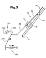
- FIG. 5 To clarify the functional interaction of the Guide Holms 20 and the securing device 28 with the Locking lever 22 and the stop means 84 and the Connection of said components with an engine brake 102nd of the device 10, reference is made to FIG.
- the engine brake 102 is on the housing 12 of the device 10 in the region of the drive 15 is provided and is shown in Fig. 5 only schematically.
- the engine brake 102 has a pivotally mounted Brake lever 104, the one end the position of a Braking device 106, for example, in the manner of or several brake shoes or brushes can be performed, determined and the other end is loaded by a spring 108.
- the Braking device 104 acts on the drive 15 or preferably on a pole or flywheel 110 of the drive 15.
- the spring 108th in turn acts on the brake lever 104, that the Braking device 106 in the direction of one of the flywheel 110th adjacent position is loaded, in which the drive 15 is not can be operated or a rotation of the mower blade or a Drive the wheels 14 is prevented.
- the soul 36 of the train-pressure cable 32 attacks also on the brake lever 104.
- the point of attack is here chosen so that one introduced by the soul 36 Gebschul the action of the spring 108 is opposite, so that the braking device 106 through the soul 36 of the Flywheel 110 can be lifted and an operation of the Drive 15 or a rotation of the mower blades or a drive the wheels 14 is allowed.
- the Holding device 54 tends, burdened by the weight of the Collecting container 26, to, in recesses 64 of the support elements 60 to arrive, so that a first backup of the collecting container 26 takes place. Also, the ramp-like design of the support elements 60 acts an unwanted slippage of the collecting container 26th opposite, since the support members 60 in the direction of Ejector opening 18 fall off. The stored collection container 26th tends due to its own weight, with his the Holding device 54 vertically opposite end portion in Direction of the device 12 to swing, causing a slipping additionally counteracted. In this position of the Guide Holms 20 acts on the brake device 30 on the Wheels 14 of the device 10 that this at least in essentially can not turn and the device 10 in this Inoperative position is prevented from rolling away.
- FIGS. 8 and 9 show the corresponding position of the Illustrate locking lever 22.
- the Guide bar 20 brought into the position shown in Fig. 1, FIGS. 8 and 9 show the corresponding position of the Illustrate locking lever 22.
- the Guide bar 20 brought into the position shown in Fig. 1, FIGS. 8 and 9 show the corresponding position of the Illustrate locking lever 22.
- the Guide bar 20 brought into the position shown in Fig. 1, FIGS. 8 and 9 show the corresponding position of the Illustrate locking lever 22.
- the Tapered configuration of the section 76 is the Holding device 54 during the pivoting of the Locking lever 22 in these along the contour of the Section 76 and the hook-like portion 72nd pulled in, this by the ramp-like design the support elements 60 is further favored.
- the Cover flap 24 pivots backwards and, if it is in this direction is spring-loaded, on the collecting container 26th on. If the guide rail 20 is folded backwards without a collecting container 26 placed on the receiving device 48 was, so the cover flap 24 pivots backwards until they on the housing 12 and thus the ejection opening 18 closes to prevent inadvertent access to the mowing blades to prevent. She gets over it by the spring load also held permanently in this position.
- the locking device 80th serves the guide rail 20 in his backward pivoted operating position against a to secure unintentional forward-pivoting or one Drive the device 10 to allow only if the Guide rail 20 is pivoted in his backwards Operating position is located and secured in this.
- the locking device acts 80 via the pull-push cable 32 with the safety device 28 and the engine brake 102 together.
- Fig. 8 the guide rail 20 in his completely after shown backward pivoted operating position.
- the Lifting means 84 is in the position that it occupies if the safety device 28 is not actuated or not is pivoted backwards.
- the first stop element 73 is received in the protruding edge 88 of the body 86, whereby the pivotal movement of the guide rail 20 is limited.
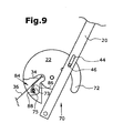
- FIG. 9 shows the position the stop means 84 shows when the safety device 28 is operated starting from the illustration in FIG. 8.
- One Pivoting the safety device 28 causes backward a movement of the soul 36 backwards. This movement causes, as described above, a pivoting of the Lifting means 84. However, this pivoting movement is in the in Figures 8 and 9 shown position of the locking lever 26 limited by the second stop member 75, on which the Edge 88 or the basic shape 86 of the securing means 84 to Plant comes.
- the soul 36 is through the Safety device 28 but further pulled backward, so that the brake lever 104 against the action of the spring 108th is moved.
- the engine brake 102 is deactivated or the braking device 106 lifted off the flywheel 110, so that the drive 15 can be operated and the mower blade or the wheels 14 can be driven.
- the first Stop element 73 is received by the edge 88 in such a way that a movement of the locking lever 22 when actuated Safety device 28 is prevented.
- the guide rail 20 is actuated safety device 28 in its operating position, creating a unintentional pivoting of the guide rail 20 forward counteracted and a certain or necessary distance between an operator and the powered device 10 is guaranteed.
- FIGS. 10 to 12 in FIG which a device is shown in a second embodiment.
- the device 10 and apart from the locking device 80 and the storage of the locking lever 22 all his essential components according to the previous presentation are trained are equally effective running or corresponding components reference numerals corresponding to Numeral assigned to the first embodiment, wherein each preceded by a 2.
- Fig. 10 shows a partly broken, schematic Representation of the device 210 viewed from above.
- On or in the Rear region 216 are two locking levers 222 provided substantially in accordance with the Locking lever 22 of the first embodiment are executed.
- the locking levers 222 are pivotable a shaft 292 placed in the rear region 216 is rotatably received by conventional bearings 2111.
- the Shaft 292 is forward by a helical spring 295 or counterclockwise. With the shaft 292 is a disk 2112 fixedly connected in the manner of a Pulley is executed.
- Left-side locking lever 222 is provided with a holder 2114 firmly connected, so that these together with the Locking lever 222 are pivoted on the shaft 292 can.
- the bracket 2114 has a relation to the device 210 on the shaft 292 inwardly extending tube 2116 on.
- the tube 2116 terminates adjacent to the disc 2112 and has its end portion 2118 a support extension 2120 on.
- the Wave 292 also works with one Locking device 280 together, which is a right-sided and a left-side stop means 284, wherein both stop means 284 on the shaft 292 to the Locking lever 222 are arranged externally adjacent.
- the Stop means 284 are fixedly connected to the shaft 292, so that they can pivot together with this.
- the stop means 284 are in the form of hook discs formed, with their outer contour according to the Representation in Figures 12 and 13 by their function is determined, as will be explained in more detail.
- FIGS. 11 and 12 are for Clarification of the dependence of the position of the Locking lever 222 and the securing means 284 of the Position of the guide rail 220 to tighten.
- the sheath 234 of the pull-push cable 232 is immovable, but preferably pivotable with the Attachment 2120 connected.
- the soul 236 of the train-pressure cable 232, extending beyond the bracket extension 2120 extends through a recess 2122 in the manner of a Groove recorded in the disk 2112 and is further through a not shown bore in the disc 2112 out and acts as shown in the first Embodiment of an engine brake 2102.
- the bore is in the direction of the engine brake 2102 a thickening in the manner provided that a movement of the Soul 236 is possible in the direction of the housing 212, the Thickening but when moving backwards at the Wall of the bore comes to the plant, so that another train at the soul 236, caused by a back-and-forth panning the securing device 228, to a back-and-forth pivoting the disc 2112 against the effect of Screw spring 295 can lead.
- Fig. 11 shows the guide rail 220 in a forward direction tilted position.
- the Locking lever 222 through its functional connection with the guide rail 220 is pivoted forward.
- the bracket extension 2120 in a forward pivoted position, so that he is in contrast to the in Fig. 10 shown extending forward position. That too Stop means 284 is pivoted forward because the shaft 292, on which it is rotatably mounted and with which it pivots, is loaded by the helical spring 295 forward.
- the safety device 228 is actuated, or perverted backwards, the soul, after all, will follow suit pulled backwards, but there is no or one only slight movement of the shaft 292 and it is caused by the Soul 236 no effect on the engine brake 2102 exerted.
- the guide rail 228 in its backward shown tilted position in which also the Locking lever 222 is pivoted to the rear.
- the Lifting means 284 is also in a backward shown tilted position, which it occupies, though the Secured device 228 pivoted backwards or is pressed.
- the Safety device 228 By pivoting the safety device 228 when pivoted backward guide rail 220, the Soul 236 pulled backward and thus moves the disc 2112, the shaft 295 and also the stop means 284 after backward. Since also the locking lever 222 in his is located in the rearward pivoted position, is the Bracket extension 2120 in the one shown in Fig. 10, according to backward extending position, arranged.
- the safety device 228 If the safety device 228 is actuated, the soul 236 pulled backwards and the shaft 292 rotates due the attacking of the soul 236 on the disc 2112 backwards or clockwise. Since the guide rail 220 in his located in reverse pivoted operating position is located the stop element 273 in such a position that the Stop means 284 so attack or strike him may be that there is another movement of the shaft 292 backwards in derogation. By a further backward-swinging the Securing device 228 will now continue to the soul 232 after dragged backwards, making them relative to the same fixed outer shell 234 is pulled backwards and she so can act on the engine brake 2102 to an operation of the To allow drive 215.
- the contour of the securing means 284 results accordingly the above description and the illustration in FIGS. 10 and 11 from the fact that it is both an attack on the Stop element 273 pivoted backward Guide bar 220 and a Vorbeischwenken the Stop element 273 on the stop means 284 during a After-forward pivoting of the guide rail 220 and one not actuated safety device 228 must allow.
- the stop means 284 has a hook-like Section 2124, the stop means 273 for locking of the guide spar 220 can overlap such that a forward-pivoting the same is prevented.
- stop element 273 arranged such is that a forward-pressing the guide rail 220 in his locked position generates a load that is characterized by the pivot axis formed by the shaft 292 extends to Shearing effects of the lifting gear Counteract 284, so that this cost-effective, be made for example of a plastic material can.
- the disc 2112 in a left-side region of the device 210 is arranged, since there also provided the engine brake 2102 is.
- the position of the disc 2112 adapted accordingly so that a favorable leadership and thus a unobstructed arrangement of the soul 236 is ensured.
- the soul 236 of the train-pressure cable 232 acts on a first disc and another, preferably also on the shaft 292 patch disc via another transmission means, for example one Cable pull on the engine brake 2102 acts to offset between the arrangement of the engine brake 2102 and the train-pressure cable 230 in a simple way to compensate or others to meet structural requirements.
- a previously described apparatus 10, 210 with a pivotable Guide rail 20, 220 offers the possibility of the device 10, 210 in forward pivoted guide rail 20, 220, for example for maintenance purposes to tilt backwards, with the Device over the guide rail 20, 220 on the ground supported.
- the guide rail 20, 220 can do this in his after front pivoted position, for example, by a simple Plug or pin connection or a bolt secured become. In this way, a comfortable access to the Bottom of the device 10, 210 allows, for example, to Cleaning or maintenance arranged from there To be able to carry out work units or the mowing knives.
Landscapes
- Life Sciences & Earth Sciences (AREA)
- Environmental Sciences (AREA)
- Harvester Elements (AREA)
- Agricultural Chemicals And Associated Chemicals (AREA)
- Catching Or Destruction (AREA)
Description
- Fig. 1
- eine Seitenansicht eines Geräts mit einem Führungsholm in einer Betriebsstellung,
- Fig. 2
- eine entsprechende Seitenansicht mit einem bezogen auf das Gerät nach vorn geschwenkten Führungsholm,
- Fig. 3
- einen vergrößerten Ausschnitt einer Verbindung zwischen dem Führungsholm und einem Gehäuse des Geräts, sowie einer Festlegeeinrichtung für einen Sammelbehälter,
- Fig. 4
- eine Explosionsdarstellung der Festlegeeinrichtung mit einer an dem Gerät vorgesehenen Sicherheitseinrichtung,
- Fig. 5
- eine schematische Darstellung des funktionalen Zusammenhangs zwischen dem Führungsholm, dem Verriegelungshebel, der Sicherheitseinrichtung und einer Motorbremse,
- Fig. 6
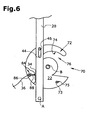
- den Führungsholm in einer bezogen auf das Gerät nach vorwärts verschwenkten Stellung, wobei sich ein Anschlagmittel in einer Position befindet, in der der Führungsholm nicht festgelegt ist,
- Fig. 7
- eine Darstellung entsprechend Fig. 6, wobei sich das Anschlagmittel in einer bezogen auf Fig. 6 verschwenkten Stellung befindet,
- Fig. 8
- den Führungsholm in einer nach rückwärts geschwenkten Stellung, wobei sich das Anschlagmittel in einer Stellung befindet, in der es den Führungsholm nicht festlegt,
- Fig. 9
- den Verriegelungshebel und den Führungsholm mit dem Anschlagmittel in einer ersten Stellung, in der der Führungsholm in seiner Betriebsstellung verriegelt ist,
- Fig. 10
- eine Ansicht eines Geräts in einer zweiten Ausführungsform mit einer Verriegelungseinrichtung von oben betrachtet,
- Fig. 11
- eine Seitenansicht des Geräts entsprechend Fig. 10 bei nach vorn geschwenktem Führungsholm und
- Fig. 12
- eine Seitenansicht entsprechend Fig. 11, wobei sich der Führungsholm in seiner Betriebsstellung befindet.
Claims (23)
- Gerät (10, 210) vorzugsweise zur Rasen-, Garten- bzw. Grundstückspflege mit einem Gehäuse (12, 212), einem beweglich mit dem Gehäuse (12, 212) verbindbaren Führungsholm (20, 220) sowie mit einem Antrieb (15, 215), wenigstens einer Arbeitseinheit und einer Sicherheitseinrichtung (28), gekennzeichnet durch eine Verriegelungseinrichtung (80, 280), die den Führungsholm (20, 220) in einer vorbestimmten Stellung festlegt, wenn die Sicherheitseinrichtung (28) einen Betrieb des Antriebs (15, 215) und/oder der Arbeitseinheit zuläßt, so daß die Verriegelung des Führungsholms abhängig von der Stellung der Sicherheitseinrichtung ist.
- Gerät nach Anspruch 1, dadurch gekennzeichnet, daß die Verriegelungseinrichtung (80, 280) direkt oder indirekt mit der Sicherheitseinrichtung (28) bzw. einer Motorbremse (102, 2102) zusammenwirken kann.
- Gerät nach einem oder mehreren der vorherigen Ansprüche, dadurch gekennzeichnet, daß die Verriegelungseinrichtung (80, 280) wenigstens ein vorzugsweise mit dem Gehäuse schwenkbar verbundenes Anschlagmittel (83, 284) aufweist, dessen Stellung durch wenigstens ein Zug-Druck-Kabel (32, 232), das vorzugsweise direkt oder indirekt mit der Sicherungseinrichtung verbunden ist, beeinflußbar ist.
- Gerät nach Anspruch 3, dadurch gekennzeichnet, daß das Zug-Druck-Kabel (32, 232) direkt oder indirekt mit einer Motorbremse (102, 2102) zusammenwirken kann.
- Gerät nach einem oder mehreren der Ansprüche 3 bis 4, dadurch gekennzeichnet, daß das Anschlagmittel (84, 284) vorzugsweise in Richtung einer geöffneten Stellung federbelastet ist.
- Gerät nach einem oder mehreren der Ansprüche 3 bis 5, dadurch gekennzeichnet, daß das Zug-Druck-Kabel (32, 232) über seine Seele (36, 236) oder über seine Außenhülle (34, 234) auf das Anschlagmittel (84, 284) wirkt.
- Gerät nach Anspruch 6, dadurch gekennzeichnet, daß das Zug-Druck-Kabel (32, 232) derart mit dem Anschlagmittel (84, 284) zusammenwirkt, daß es die Stellung der Motorbremse (102, 2120) nur dann verändern kann, wenn sich das Anschlagmittel (84, 284) in einer vorgegebenen Stellung, in der es den Führungsholm (20, 220) in einer vorzugsweise von dem Gehäuse (12, 212) weg geschwenkten Betriebsstellung sichert, befindet.
- Gerät nach einem oder mehreren der vorherigen Ansprüche, gekennzeichnet durch zumindest eine Festlegeeinrichtung, durch die wenigstens ein Anbauteil in Abhängigkeit von der Stellung des Führungsholms (20) an dem Gehäuse (12) sicherbar ist.
- Gerät nach Anspruch 8, dadurch gekennzeichnet, daß der Anbauteil ein Sammelbehälter (26) und/oder eine Abdeckklappe (24) und/oder eine Leiteinrichtung ist.
- Gerät nach einem oder mehreren der vorherigen Ansprüche, dadurch gekennzeichnet, daß der Führungsholm (20) mit dem Gerät (10) schwenkbar verbindbar ist.
- Gerät nach einem oder mehreren Ansprüche 8 bis 10, dadurch gekennzeichnet, daß die Festlegeeinrichtung wenigstens einen vorzugsweise mit dem Gehäuse (12, 212) schwenkbar verbindbaren Verriegelungshebel (22, 222) aufweist, der vorzugsweise mit an dem Anbauteil bzw. einem mit dem Anbauteil verbindbaren Bauteil an- oder eingreifen kann.
- Gerät nach Anspruch 11, dadurch gekennzeichnet, daß das Anschlagmittel (84, 284) mit wenigstens einem Anschlagelement (73, 75, 273), das vorzugsweise an dem Verriegelungshebel (22, 222) angeordnet ist, zusammenwirken kann.
- Gerät nach Anspruch 11 oder 12, dadurch gekennzeichnet, daß der Verriegelungshebel (22, 222) zumindest bereichsweise in der Art einer Scheibe ausgeführt ist.
- Gerät nach einem oder mehreren der vorherigen Ansprüche 11 bis 13, dadurch gekennzeichnet, daß der Verriegelungshebel (22, 222) einen hakenartigen Abschnitt (32) aufweist, der vorzugsweise an oder in eine(r) Halteeinrichtung (54) des Anbauteils an-/eingreift.
- Gerät nach einem oder mehreren der Ansprüche 11 bis 14, dadurch gekennzeichnet, daß der Führungsholm (20) und der Verriegelungshebel (22) voneinander radial beabstandete Schwenkachsen (A, B) aufweisen.
- Gerät nach einem oder mehreren der Ansprüche 11 bis 15, dadurch gekennzeichnet, daß der Verriegelungshebel (22, 222) und der Führungsholm (20, 220) direkt oder indirekt verbindbar sind, wobei vorzugsweise eine Ausnehmung und ein in diese eingreifender Bauteil an dem Verriegelungshebel (22, 222) bzw. an dem Führungsholm (20, 220) vorgesehen sind.
- Gerät nach Anspruch 16, dadurch gekennzeichnet, daß die Aussparung in der Art eines Langlochs (44) ausgeführt ist.
- Gerät nach einem oder mehreren der Ansprüche 8 bis 17, gekennzeichnet durch ein vorzugsweise rampenartiges Stützelement (60) das mit der Verriegelungseinrichtung zur Sicherung des Anbauteils zusammenwirken kann.
- Gerät nach einem oder mehreren der vorherigen Ansprüche, dadurch gekennzeichnet, daß ein Betrieb des Antriebs (15, 215) nicht möglich ist, wenn sich der Führungsholm (20, 220) nicht in einer bestimmten Stellung, die vorzugsweise seine Betriebsstellung ist, befindet.
- Gerät nach einem oder mehreren der Ansprüche 8 bis 19, dadurch gekennzeichnet, daß die Verriegelungseinrichtung oder der Führungsholm (20, 220) direkt oder indirekt derart mit wenigstens einem Rad (14, 214) des Geräts (10, 210) zusammenwirken kann, daß dieses zumindest im wesentlichen an einem Drehen gehindert werden.
- Gerät nach einem oder mehreren der vorherigen Ansprüche, dadurch gekennzeichnet, daß der Führungsholm (20, 220) in eine Stellung bringbar ist, in der sich das Gerät (10, 210) in einem nach rückwärts geschwenkten Zustand mittels des Führungsholms (20, 220) derart auf einem Untergrund abstützen kann, daß es sich in einer stabilen Gleichgewichtslage befindet.
- Gerät nach Anspruch 21, dadurch gekennzeichnet, daß es sich bei der Stellung um eine bezogen auf das Gehäuse (12) nach vorn geschwenkte Außer-Betriebs-Stellung des Führungsholms (20, 220) handelt.
- Gerät nach Anspruch 21 oder 22, dadurch gekennzeichnet, daß der Führungsholm (20, 220) zumindest in dieser Stellung festlegbar ist.
Applications Claiming Priority (2)
| Application Number | Priority Date | Filing Date | Title |
|---|---|---|---|
| DE10043240 | 2000-09-02 | ||
| DE10043240A DE10043240A1 (de) | 2000-09-02 | 2000-09-02 | Gerät zur Rasen-, Garten-bzw.Grundstückspflege |
Publications (2)
| Publication Number | Publication Date |
|---|---|
| EP1183934A1 EP1183934A1 (de) | 2002-03-06 |
| EP1183934B1 true EP1183934B1 (de) | 2005-06-15 |
Family
ID=7654727
Family Applications (1)
| Application Number | Title | Priority Date | Filing Date |
|---|---|---|---|
| EP01120123A Expired - Lifetime EP1183934B1 (de) | 2000-09-02 | 2001-08-22 | Gerät zur Rasen-, Garten- bzw. Grundstückspflege |
Country Status (3)
| Country | Link |
|---|---|
| EP (1) | EP1183934B1 (de) |
| AT (1) | ATE297653T1 (de) |
| DE (2) | DE10043240A1 (de) |
Families Citing this family (5)
| Publication number | Priority date | Publication date | Assignee | Title |
|---|---|---|---|---|
| DE10307658B3 (de) * | 2003-02-21 | 2004-09-30 | Werner Kress | Rasenmäher mit Sicherheitsschalteinrichtung |
| CN106818024A (zh) * | 2017-01-03 | 2017-06-13 | 天佑电器(苏州)有限公司 | 园林工具推杆机构及具有该机构的园林工具 |
| CN108848881A (zh) * | 2018-06-13 | 2018-11-23 | 岳西县万盈生态农业科技有限公司 | 一种手动割草机 |
| US11937544B2 (en) * | 2021-03-02 | 2024-03-26 | Honda Motor Co., Ltd. | Electric mower switch system |
| EP4573877A4 (de) * | 2022-09-27 | 2025-11-12 | Zhejiang Yat Electrical Appliance Co Ltd | Mäher und verfahren zur steuerung des starts und stopps des mähers |
Family Cites Families (9)
| Publication number | Priority date | Publication date | Assignee | Title |
|---|---|---|---|---|
| GB816145A (en) * | 1955-02-15 | 1959-07-08 | Sunbeam Corp | Lawn mower |
| FR2237566A1 (en) * | 1973-07-18 | 1975-02-14 | Bernard Moteurs | Lawn mower with motor driven blades - cutting speed is controlled by pivoting the mower guide handle |
| IT1067195B (it) * | 1976-07-27 | 1985-03-12 | Concord Meccanica Re Gi Srl | Manico regolabile per tagliaerba e simili apparecchi |
| US4753062A (en) * | 1987-06-11 | 1988-06-28 | Capro, Inc. | Lawn mower and safety control therefor |
| DE9005367U1 (de) * | 1990-05-11 | 1990-08-23 | Hessabi, Iradj, Dipl.-Ing., 4902 Bad Salzuflen | Ultraschallmähvorrichtung |
| JP3150553B2 (ja) * | 1994-12-22 | 2001-03-26 | リョービ株式会社 | ハンドル折りたたみ機構を有する芝刈機 |
| FR2768300B1 (fr) * | 1997-09-12 | 1999-11-26 | Wolf Outils | Tondeuse a gazon comportant un dispositif de securite prevenant contre l'acces a la lame de coupe en rotation |
| FR2780375B1 (fr) * | 1998-06-30 | 2000-09-08 | Dominique Legendre | Tondeuse ou machine analogue a guidon articule |
| DE19839203C2 (de) * | 1998-08-28 | 2000-10-26 | Stella Engineering Gmbh | Sicherheitsvorrichtung für handgeführte Arbeitsgeräte mit motorischem Antrieb |
-
2000
- 2000-09-02 DE DE10043240A patent/DE10043240A1/de not_active Withdrawn
-
2001
- 2001-08-22 DE DE50106506T patent/DE50106506D1/de not_active Expired - Lifetime
- 2001-08-22 EP EP01120123A patent/EP1183934B1/de not_active Expired - Lifetime
- 2001-08-22 AT AT01120123T patent/ATE297653T1/de not_active IP Right Cessation
Also Published As
| Publication number | Publication date |
|---|---|
| DE10043240A1 (de) | 2002-03-14 |
| EP1183934A1 (de) | 2002-03-06 |
| ATE297653T1 (de) | 2005-07-15 |
| DE50106506D1 (de) | 2005-07-21 |
Similar Documents
| Publication | Publication Date | Title |
|---|---|---|
| EP1295521B1 (de) | Arbeitsgerät und Gerät zur Rasen-,Garten- und Grundstückspflege | |
| DE69806851T2 (de) | Selbstfahrender Rasenmäher mit Grasfangbehälter | |
| EP0277343B1 (de) | Mähmaschine | |
| EP0797026B1 (de) | Reibradantrieb | |
| EP0073359B1 (de) | Verriegelungsvorrichtung für Mähmaschinen | |
| DE69823072T2 (de) | Rasenmäher mit Sicherheitsvorrichtung zur Verhinderung von Zugang zum rotierenden Schneidmesser | |
| DE69415708T2 (de) | Frontmäher mit einem zentralen Grassbehälter zwischen Vorder- und Hinterrädern | |
| DE60320097T2 (de) | Heuwerbungsmaschine | |
| DE3402065C1 (de) | Schutzeinrichtung zum Verhindern der Beruehrung mindestens eines sich drehenden Teiles | |
| EP0933016B1 (de) | Tragvorrichtung und Grundstückspflegefahrzeug | |
| DE69718206T2 (de) | Verriegelung von schwenkbaren rad | |
| EP1183931B1 (de) | Gerät zur Rasen-, Garten- bzw. Grundstückspflege | |
| DE10043240A1 (de) | Gerät zur Rasen-, Garten-bzw.Grundstückspflege | |
| DE3603902A1 (de) | Motorgetriebener rasenmaeher | |
| EP1183936B1 (de) | Gerät zur Rasen-, Garten- bzw Grundstückspflege | |
| DE2117667A1 (de) | Von einem Fahrzeug aufgenommene undangetriebene Rasenmähvorrichtung | |
| EP0689758B1 (de) | Bodenbearbeitungsgerät mit Totmannsicherung | |
| DE3222503A1 (de) | Stockraeumgeraet | |
| EP1564424B1 (de) | Gerät zur Rasen-, Garten- bzw. Grundstückspflege | |
| EP0648407B1 (de) | Heuwerbungsmaschine | |
| DE19532423C2 (de) | Landschaftspflegegerät | |
| DE3305382A1 (de) | Ladewagen mit anbau-seitenmaeh-raeumwerk oder raeumwerk | |
| DE202023100512U1 (de) | Push-Push-Verriegelung für mobiles Rasenbehandlungsgerät | |
| DE4407546A1 (de) | Vorrichtung zum Mähen | |
| DE8803171U1 (de) | Mähwerk |
Legal Events
| Date | Code | Title | Description |
|---|---|---|---|
| PUAI | Public reference made under article 153(3) epc to a published international application that has entered the european phase |
Free format text: ORIGINAL CODE: 0009012 |
|
| AK | Designated contracting states |
Kind code of ref document: A1 Designated state(s): AT BE CH CY DE DK ES FI FR GB GR IE IT LI LU MC NL PT SE TR |
|
| AX | Request for extension of the european patent |
Free format text: AL;LT;LV;MK;RO;SI |
|
| 17P | Request for examination filed |
Effective date: 20020906 |
|
| AKX | Designation fees paid |
Free format text: AT BE CH CY DE DK ES FI FR GB GR IE IT LI LU MC NL PT SE TR |
|
| 17Q | First examination report despatched |
Effective date: 20040427 |
|
| GRAP | Despatch of communication of intention to grant a patent |
Free format text: ORIGINAL CODE: EPIDOSNIGR1 |
|
| GRAS | Grant fee paid |
Free format text: ORIGINAL CODE: EPIDOSNIGR3 |
|
| GRAA | (expected) grant |
Free format text: ORIGINAL CODE: 0009210 |
|
| AK | Designated contracting states |
Kind code of ref document: B1 Designated state(s): AT BE CH CY DE DK ES FI FR GB GR IE IT LI LU MC NL PT SE TR |
|
| PG25 | Lapsed in a contracting state [announced via postgrant information from national office to epo] |
Ref country code: NL Free format text: LAPSE BECAUSE OF FAILURE TO SUBMIT A TRANSLATION OF THE DESCRIPTION OR TO PAY THE FEE WITHIN THE PRESCRIBED TIME-LIMIT Effective date: 20050615 Ref country code: FI Free format text: LAPSE BECAUSE OF FAILURE TO SUBMIT A TRANSLATION OF THE DESCRIPTION OR TO PAY THE FEE WITHIN THE PRESCRIBED TIME-LIMIT Effective date: 20050615 Ref country code: TR Free format text: LAPSE BECAUSE OF FAILURE TO SUBMIT A TRANSLATION OF THE DESCRIPTION OR TO PAY THE FEE WITHIN THE PRESCRIBED TIME-LIMIT Effective date: 20050615 Ref country code: IE Free format text: LAPSE BECAUSE OF FAILURE TO SUBMIT A TRANSLATION OF THE DESCRIPTION OR TO PAY THE FEE WITHIN THE PRESCRIBED TIME-LIMIT Effective date: 20050615 |
|
| REG | Reference to a national code |
Ref country code: GB Ref legal event code: FG4D Free format text: NOT ENGLISH Ref country code: CH Ref legal event code: EP |
|
| REF | Corresponds to: |
Ref document number: 50106506 Country of ref document: DE Date of ref document: 20050721 Kind code of ref document: P |
|
| REG | Reference to a national code |
Ref country code: IE Ref legal event code: FG4D Free format text: LANGUAGE OF EP DOCUMENT: GERMAN |
|
| PG25 | Lapsed in a contracting state [announced via postgrant information from national office to epo] |
Ref country code: LU Free format text: LAPSE BECAUSE OF NON-PAYMENT OF DUE FEES Effective date: 20050822 Ref country code: CY Free format text: LAPSE BECAUSE OF FAILURE TO SUBMIT A TRANSLATION OF THE DESCRIPTION OR TO PAY THE FEE WITHIN THE PRESCRIBED TIME-LIMIT Effective date: 20050822 Ref country code: AT Free format text: LAPSE BECAUSE OF NON-PAYMENT OF DUE FEES Effective date: 20050822 |
|
| PG25 | Lapsed in a contracting state [announced via postgrant information from national office to epo] |
Ref country code: CH Free format text: LAPSE BECAUSE OF NON-PAYMENT OF DUE FEES Effective date: 20050831 Ref country code: MC Free format text: LAPSE BECAUSE OF NON-PAYMENT OF DUE FEES Effective date: 20050831 Ref country code: BE Free format text: LAPSE BECAUSE OF NON-PAYMENT OF DUE FEES Effective date: 20050831 Ref country code: LI Free format text: LAPSE BECAUSE OF NON-PAYMENT OF DUE FEES Effective date: 20050831 |
|
| PG25 | Lapsed in a contracting state [announced via postgrant information from national office to epo] |
Ref country code: DK Free format text: LAPSE BECAUSE OF FAILURE TO SUBMIT A TRANSLATION OF THE DESCRIPTION OR TO PAY THE FEE WITHIN THE PRESCRIBED TIME-LIMIT Effective date: 20050915 Ref country code: SE Free format text: LAPSE BECAUSE OF FAILURE TO SUBMIT A TRANSLATION OF THE DESCRIPTION OR TO PAY THE FEE WITHIN THE PRESCRIBED TIME-LIMIT Effective date: 20050915 Ref country code: GR Free format text: LAPSE BECAUSE OF FAILURE TO SUBMIT A TRANSLATION OF THE DESCRIPTION OR TO PAY THE FEE WITHIN THE PRESCRIBED TIME-LIMIT Effective date: 20050915 |
|
| GBT | Gb: translation of ep patent filed (gb section 77(6)(a)/1977) |
Effective date: 20050831 |
|
| PG25 | Lapsed in a contracting state [announced via postgrant information from national office to epo] |
Ref country code: ES Free format text: LAPSE BECAUSE OF FAILURE TO SUBMIT A TRANSLATION OF THE DESCRIPTION OR TO PAY THE FEE WITHIN THE PRESCRIBED TIME-LIMIT Effective date: 20050926 |
|
| PG25 | Lapsed in a contracting state [announced via postgrant information from national office to epo] |
Ref country code: PT Free format text: LAPSE BECAUSE OF FAILURE TO SUBMIT A TRANSLATION OF THE DESCRIPTION OR TO PAY THE FEE WITHIN THE PRESCRIBED TIME-LIMIT Effective date: 20051124 |
|
| NLV1 | Nl: lapsed or annulled due to failure to fulfill the requirements of art. 29p and 29m of the patents act | ||
| REG | Reference to a national code |
Ref country code: IE Ref legal event code: FD4D |
|
| REG | Reference to a national code |
Ref country code: CH Ref legal event code: PL |
|
| ET | Fr: translation filed | ||
| PLBE | No opposition filed within time limit |
Free format text: ORIGINAL CODE: 0009261 |
|
| STAA | Information on the status of an ep patent application or granted ep patent |
Free format text: STATUS: NO OPPOSITION FILED WITHIN TIME LIMIT |
|
| 26N | No opposition filed |
Effective date: 20060316 |
|
| BERE | Be: lapsed |
Owner name: SABO-MASCHINENFABRIK G.M.B.H. Effective date: 20050831 |
|
| REG | Reference to a national code |
Ref country code: FR Ref legal event code: PLFP Year of fee payment: 16 |
|
| REG | Reference to a national code |
Ref country code: FR Ref legal event code: PLFP Year of fee payment: 17 |
|
| REG | Reference to a national code |
Ref country code: FR Ref legal event code: PLFP Year of fee payment: 18 |
|
| PGFP | Annual fee paid to national office [announced via postgrant information from national office to epo] |
Ref country code: GB Payment date: 20200827 Year of fee payment: 20 Ref country code: FR Payment date: 20200825 Year of fee payment: 20 Ref country code: DE Payment date: 20200721 Year of fee payment: 20 |
|
| PGFP | Annual fee paid to national office [announced via postgrant information from national office to epo] |
Ref country code: IT Payment date: 20200821 Year of fee payment: 20 |
|
| REG | Reference to a national code |
Ref country code: DE Ref legal event code: R071 Ref document number: 50106506 Country of ref document: DE |
|
| REG | Reference to a national code |
Ref country code: GB Ref legal event code: PE20 Expiry date: 20210821 |
|
| PG25 | Lapsed in a contracting state [announced via postgrant information from national office to epo] |
Ref country code: GB Free format text: LAPSE BECAUSE OF EXPIRATION OF PROTECTION Effective date: 20210821 |