EP1183908B1 - Hinterohr-hörgerät - Google Patents
Hinterohr-hörgerät Download PDFInfo
- Publication number
- EP1183908B1 EP1183908B1 EP99924638A EP99924638A EP1183908B1 EP 1183908 B1 EP1183908 B1 EP 1183908B1 EP 99924638 A EP99924638 A EP 99924638A EP 99924638 A EP99924638 A EP 99924638A EP 1183908 B1 EP1183908 B1 EP 1183908B1
- Authority
- EP
- European Patent Office
- Prior art keywords
- behind
- contact
- hearing device
- ear hearing
- hearing aid
- Prior art date
- Legal status (The legal status is an assumption and is not a legal conclusion. Google has not performed a legal analysis and makes no representation as to the accuracy of the status listed.)
- Expired - Lifetime
Links
- 239000004033 plastic Substances 0.000 claims description 5
- 229920003023 plastic Polymers 0.000 claims description 5
- 230000006870 function Effects 0.000 abstract description 5
- 230000005540 biological transmission Effects 0.000 description 5
- 230000008878 coupling Effects 0.000 description 4
- 238000010168 coupling process Methods 0.000 description 4
- 238000005859 coupling reaction Methods 0.000 description 4
- 238000005538 encapsulation Methods 0.000 description 4
- 239000006187 pill Substances 0.000 description 3
- MOVRNJGDXREIBM-UHFFFAOYSA-N aid-1 Chemical compound O=C1NC(=O)C(C)=CN1C1OC(COP(O)(=O)OC2C(OC(C2)N2C3=C(C(NC(N)=N3)=O)N=C2)COP(O)(=O)OC2C(OC(C2)N2C3=C(C(NC(N)=N3)=O)N=C2)COP(O)(=O)OC2C(OC(C2)N2C3=C(C(NC(N)=N3)=O)N=C2)COP(O)(=O)OC2C(OC(C2)N2C(NC(=O)C(C)=C2)=O)COP(O)(=O)OC2C(OC(C2)N2C3=C(C(NC(N)=N3)=O)N=C2)COP(O)(=O)OC2C(OC(C2)N2C3=C(C(NC(N)=N3)=O)N=C2)COP(O)(=O)OC2C(OC(C2)N2C3=C(C(NC(N)=N3)=O)N=C2)COP(O)(=O)OC2C(OC(C2)N2C(NC(=O)C(C)=C2)=O)COP(O)(=O)OC2C(OC(C2)N2C3=C(C(NC(N)=N3)=O)N=C2)COP(O)(=O)OC2C(OC(C2)N2C3=C(C(NC(N)=N3)=O)N=C2)COP(O)(=O)OC2C(OC(C2)N2C3=C(C(NC(N)=N3)=O)N=C2)COP(O)(=O)OC2C(OC(C2)N2C(NC(=O)C(C)=C2)=O)COP(O)(=O)OC2C(OC(C2)N2C3=C(C(NC(N)=N3)=O)N=C2)COP(O)(=O)OC2C(OC(C2)N2C3=C(C(NC(N)=N3)=O)N=C2)COP(O)(=O)OC2C(OC(C2)N2C3=C(C(NC(N)=N3)=O)N=C2)CO)C(O)C1 MOVRNJGDXREIBM-UHFFFAOYSA-N 0.000 description 2
- 238000010276 construction Methods 0.000 description 2
- 238000003780 insertion Methods 0.000 description 2
- 230000037431 insertion Effects 0.000 description 2
- 239000000463 material Substances 0.000 description 2
- 239000005871 repellent Substances 0.000 description 2
- 230000001629 suppression Effects 0.000 description 2
- -1 Polyethylene Polymers 0.000 description 1
- 239000004698 Polyethylene Substances 0.000 description 1
- 230000003321 amplification Effects 0.000 description 1
- 239000011248 coating agent Substances 0.000 description 1
- 238000000576 coating method Methods 0.000 description 1
- 230000001447 compensatory effect Effects 0.000 description 1
- 238000011109 contamination Methods 0.000 description 1
- 230000006735 deficit Effects 0.000 description 1
- 230000006866 deterioration Effects 0.000 description 1
- 230000003670 easy-to-clean Effects 0.000 description 1
- 230000000694 effects Effects 0.000 description 1
- 230000004927 fusion Effects 0.000 description 1
- 239000012528 membrane Substances 0.000 description 1
- 229910000595 mu-metal Inorganic materials 0.000 description 1
- 238000003199 nucleic acid amplification method Methods 0.000 description 1
- 210000000056 organ Anatomy 0.000 description 1
- 238000002559 palpation Methods 0.000 description 1
- 230000035515 penetration Effects 0.000 description 1
- 229920000573 polyethylene Polymers 0.000 description 1
- 230000002940 repellent Effects 0.000 description 1
- 238000007493 shaping process Methods 0.000 description 1
- 230000008054 signal transmission Effects 0.000 description 1
- 239000002689 soil Substances 0.000 description 1
- 210000004243 sweat Anatomy 0.000 description 1
- XLYOFNOQVPJJNP-UHFFFAOYSA-N water Substances O XLYOFNOQVPJJNP-UHFFFAOYSA-N 0.000 description 1
Images

Classifications
-
- H—ELECTRICITY
- H04—ELECTRIC COMMUNICATION TECHNIQUE
- H04R—LOUDSPEAKERS, MICROPHONES, GRAMOPHONE PICK-UPS OR LIKE ACOUSTIC ELECTROMECHANICAL TRANSDUCERS; DEAF-AID SETS; PUBLIC ADDRESS SYSTEMS
- H04R25/00—Deaf-aid sets, i.e. electro-acoustic or electro-mechanical hearing aids; Electric tinnitus maskers providing an auditory perception
- H04R25/60—Mounting or interconnection of hearing aid parts, e.g. inside tips, housings or to ossicles
-
- H—ELECTRICITY
- H04—ELECTRIC COMMUNICATION TECHNIQUE
- H04R—LOUDSPEAKERS, MICROPHONES, GRAMOPHONE PICK-UPS OR LIKE ACOUSTIC ELECTROMECHANICAL TRANSDUCERS; DEAF-AID SETS; PUBLIC ADDRESS SYSTEMS
- H04R25/00—Deaf-aid sets, i.e. electro-acoustic or electro-mechanical hearing aids; Electric tinnitus maskers providing an auditory perception
-
- H—ELECTRICITY
- H01—ELECTRIC ELEMENTS
- H01H—ELECTRIC SWITCHES; RELAYS; SELECTORS; EMERGENCY PROTECTIVE DEVICES
- H01H2300/00—Orthogonal indexing scheme relating to electric switches, relays, selectors or emergency protective devices covered by H01H
- H01H2300/004—Application hearing aid
-
- H—ELECTRICITY
- H04—ELECTRIC COMMUNICATION TECHNIQUE
- H04R—LOUDSPEAKERS, MICROPHONES, GRAMOPHONE PICK-UPS OR LIKE ACOUSTIC ELECTROMECHANICAL TRANSDUCERS; DEAF-AID SETS; PUBLIC ADDRESS SYSTEMS
- H04R2225/00—Details of deaf aids covered by H04R25/00, not provided for in any of its subgroups
- H04R2225/021—Behind the ear [BTE] hearing aids
-
- H—ELECTRICITY
- H04—ELECTRIC COMMUNICATION TECHNIQUE
- H04R—LOUDSPEAKERS, MICROPHONES, GRAMOPHONE PICK-UPS OR LIKE ACOUSTIC ELECTROMECHANICAL TRANSDUCERS; DEAF-AID SETS; PUBLIC ADDRESS SYSTEMS
- H04R2225/00—Details of deaf aids covered by H04R25/00, not provided for in any of its subgroups
- H04R2225/61—Aspects relating to mechanical or electronic switches or control elements, e.g. functioning
-
- H—ELECTRICITY
- H04—ELECTRIC COMMUNICATION TECHNIQUE
- H04R—LOUDSPEAKERS, MICROPHONES, GRAMOPHONE PICK-UPS OR LIKE ACOUSTIC ELECTROMECHANICAL TRANSDUCERS; DEAF-AID SETS; PUBLIC ADDRESS SYSTEMS
- H04R25/00—Deaf-aid sets, i.e. electro-acoustic or electro-mechanical hearing aids; Electric tinnitus maskers providing an auditory perception
- H04R25/60—Mounting or interconnection of hearing aid parts, e.g. inside tips, housings or to ossicles
- H04R25/602—Mounting or interconnection of hearing aid parts, e.g. inside tips, housings or to ossicles of batteries
-
- H—ELECTRICITY
- H04—ELECTRIC COMMUNICATION TECHNIQUE
- H04R—LOUDSPEAKERS, MICROPHONES, GRAMOPHONE PICK-UPS OR LIKE ACOUSTIC ELECTROMECHANICAL TRANSDUCERS; DEAF-AID SETS; PUBLIC ADDRESS SYSTEMS
- H04R25/00—Deaf-aid sets, i.e. electro-acoustic or electro-mechanical hearing aids; Electric tinnitus maskers providing an auditory perception
- H04R25/60—Mounting or interconnection of hearing aid parts, e.g. inside tips, housings or to ossicles
- H04R25/603—Mounting or interconnection of hearing aid parts, e.g. inside tips, housings or to ossicles of mechanical or electronic switches or control elements
-
- H—ELECTRICITY
- H04—ELECTRIC COMMUNICATION TECHNIQUE
- H04R—LOUDSPEAKERS, MICROPHONES, GRAMOPHONE PICK-UPS OR LIKE ACOUSTIC ELECTROMECHANICAL TRANSDUCERS; DEAF-AID SETS; PUBLIC ADDRESS SYSTEMS
- H04R25/00—Deaf-aid sets, i.e. electro-acoustic or electro-mechanical hearing aids; Electric tinnitus maskers providing an auditory perception
- H04R25/60—Mounting or interconnection of hearing aid parts, e.g. inside tips, housings or to ossicles
- H04R25/609—Mounting or interconnection of hearing aid parts, e.g. inside tips, housings or to ossicles of circuitry
-
- H—ELECTRICITY
- H04—ELECTRIC COMMUNICATION TECHNIQUE
- H04R—LOUDSPEAKERS, MICROPHONES, GRAMOPHONE PICK-UPS OR LIKE ACOUSTIC ELECTROMECHANICAL TRANSDUCERS; DEAF-AID SETS; PUBLIC ADDRESS SYSTEMS
- H04R25/00—Deaf-aid sets, i.e. electro-acoustic or electro-mechanical hearing aids; Electric tinnitus maskers providing an auditory perception
- H04R25/65—Housing parts, e.g. shells, tips or moulds, or their manufacture
Definitions
- the present invention relates to a behind-the-ear hearing aid according to the preamble of claim 1.
- Such hearing aids are known in the art, for example from the documents EP 0 349 835 A and US 4,634,815 A ,
- the present invention aims to remedy the disadvantages mentioned.
- the hearing aid according to the invention is characterized according to the characterizing part of claim 1.
- two categories of switching functions are combined on one and the same actuating member, namely, in the mentioned positions, preferably ON / OFF switching of the hearing aid and in the second actuating direction, for example adjustment of the amplification.
- the ease of use is notably increased, it is readily possible to distinguish the two different types of actuation on a designated operating switch.
- a single operating switch provided according to the invention requires less volume and, moreover, the hearing aid as a whole becomes simpler by virtue of electrical connections to switching devices only within the scope of the invention provided an actuator must be performed.
- one of the positions is used as a switch-on position of the hearing aid, the other as a switch-off position, and the actuator acts as a toggle switch when actuated in the second direction.
- the actuating member is tilt-mounted on a slide which is displaceable in a substantially linear manner and has a contact which can be brought into contact with a device-fixed switch contact by actuation in the second direction.
- This contact is preferably made of rubber-elastic plastic, preferably hat-shaped, as is known from computer keyboard mats or remote keyboards.
- the first operating direction of the operating member is located substantially in the direction of generatrices of the device body, preferably along curvature-outer side generatrices, based on the device body deflection, and it is the second direction of actuation perpendicular to the device body wall.
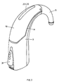
- Fig. 1 is shown in a partially simplified longitudinal section illustration of the inventive rear ear hearing aid as a whole, what initially the individual function blocks or functional parts to be described.
- the hearing aid 1 comprises a horn-shaped curved, tubular base body with a center axis A, which at the thinner, bent end, as an acoustic output, a connection piece 5 for a leading into the ear coupling pipe.
- the connecting piece 5 is replaceable on a pipe socket 9, which sits on a base housing 3, plugged or screwed.
- the inner channel 7 of the connecting piece 5 continues through the pipe socket 9 into a transmission channel 11 in the base housing 3.
- the transmission channel 11 in turn is coupled to an electrical / acoustic transducer assembly 15 in a compartment 13 of the base housing 3.
- the transmission channel 11 extends along the inner curvature of the base housing 3 such that the outside curvature side, a microphone assembly 17 finds room.
- a lid 19 is formed in this area and locked in the areas of the culmination point of the device by means of a plug-in axis 21.
- the cover 19 extends along generatrices M of the device body until, Fig. 1 ,
- the microphone assembly 17 is accessible upon removal of the hinged lid 19 and preferably only on a Flexprint tab (not shown) electrically contacted, folded over the transmission channel 11 and is located on a sound entry slot 23rd
- the insert 25 is acoustically “transparent” and has a plurality of passages between the environment U and a compensation volume V, the latter being left between the discrete microphone entry openings (not shown) and said insert.
- the insert 25 is preferably made of a sintered material, in particular of sintered material Polyethylene and thereby more preferably water repellent coated. It further forms a mesh fineness between 10 ⁇ m and 200 ⁇ m with an open porosity of preferably more than 70%.
- microphone assembly 17 and insert 25 are arranged in the slot 23 on the hearing aid 1, that they are exposed to possible hearing aid, as possible no air pressure of the environment U, by - as out Fig. 1 visible - are positioned in the region of the crest of the horn-shaped curved tubular body.
- the proposed intermediate volume V in the sense of a "common mode" suppression, that along the insert 25 differently coupled, same acoustic signals due the compensatory effect of the volume V tends to cancel.
- the insert 25 acts as a soil protection and is easy to clean thanks to their preferably water-repellent coating.
- a cylindrical flat battery or a suitably shaped battery 33 is inserted, such that the axis of the battery cylinder, with its end faces 33 u and 33 o , at least substantially, coaxial with the longitudinal axis A. of the main body lies.
- a first resilient contact 35 is provided at the base 30 of the battery compartment 29, centered in the axis A, a second 37 resiliently contacts the side surface of the battery 33.
- the battery compartment 29 can be closed by a cover 39 which is in the closed position in relation to the axis A and which is pivotally or bayonet-mounted on the base housing 3, at 41, or on the battery compartment 29.
- This transverse arrangement of the battery 33 on the hearing aid has significant advantages:
- the area closed by the lid 39 is relatively large, which, as will be explained later, can be used further.
- the battery compartment cover 39 is located at the lowest point of the device and the Deckelstossstellen to the base housing 3 are transverse to the axis A, penetration of sweat in the battery compartment is hardly critical.
- the contacts 37 and 35 are protected within the compartment, the cover 39 carries no electrical contacts. Further, because the substantially cylindrical interior of the main body 3 is utilized, there is practically no unused, lost space.
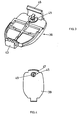
- Fig. 3 is, in perspective, a preferred embodiment of the battery cover 39 shown formed as a hinged lid.
- the Schnappscharnierteil 43 he is simply from the pivot bearing 41 according Fig. 1 unlatched or latched to it.
- it further comprises a locking lock 45, together with a resilient latch 46.
- Fig. 4 is the lid 39 according to Fig. 1 shown in external view.
- the locking lock 45 is externally operable only with a tool, such as a screwdriver, and has for this purpose, on a turntable 47, an engagement slot 49.
- the board 47 which is installed only when mounting the locking lock 45 on the hinged lid 39 is specifically colored, in two versions, eg red and blue, which this part is also used as an indication of whether the respective hearing aid is a device for left or right Ear is.
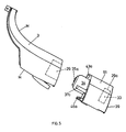
- the illustrated embodiment of the battery compartment 29, in particular the fact that the flat battery cylinder is coaxial with the axis A of the hearing aid, has a further, substantial advantage.
- Fig. 1 illustrated battery compartment, as in Fig. 5 represented, converted.
- the battery 33 is removed from the compartment and instead of the plug-in part 34 of a corresponding additional module 51 is inserted, electrically contacted to the battery contacts corresponding contact points 35a and 37a.
- the now acting as the actual battery compartment tray 29a with battery 33 is now provided on the additional module 51 and, accordingly, the lid 39, for example, removed from the base housing 3 and latched on the additional module or is engaged in a bayonet.
- a plurality of such modules 51 am in Fig. 1 illustrated basic module of the hearing aid are stacked.
- the respective fixation of the additional modules 51 is preferably carried out with a provided on the modules 51 Einrastpartie 43a, analogous to the hinge 43 on the hinged lid 39, and analogous to the snap part 46 formed on said hinged lid 39 snap part 46a or, in the bayonet lock, by appropriate insertion and twist locking.
- Fig. 6 is, simplified, the structure and storage of the mentioned arrangement 15 on the base housing 3 and in view according to Fig. 1 shown.
- the assembly 15 includes, encapsulated in a speaker housing 53, the speaker assembly (not shown) with a speaker diaphragm.
- the speaker assembly (not shown) with a speaker diaphragm.
- coupling openings the sound waves excited by the speaker diaphragm are coupled from the membrane-back space in the speaker housing 53 in the surrounding space U 53 of the speaker housing 53.
- the acoustic signals - as shown by the arrow S - to the in Fig. 1 apparent transmission channel 11 is coupled.
- the speaker housing 53 is supported on all sides in resilient, preferably in rubber-elastic bearings 57, substantially free swinging. Due to the bearings 57, the relatively large space U 53 is defined between loudspeaker housing outer wall and an encapsulation 59, which leads to a considerable increase in the bass tones.
- the membrane-rear resonance space is increased by the space U 53 many times. So that the space U 53 is acoustically fully effective, the enclosure 59 and its holder 61 are tightly connected.
- the storage volume for the speaker assembly is used optimally acoustically.
- the encapsulation 59 furthermore preferably acts as a magnetic shielding housing and is preferably made from ⁇ -metal for this purpose. It is cup-shaped and is formed on the holder 61, designed as a plastic carrier part, sealingly hooked. Between encapsulation 59, bracket 61 on the one hand and speaker housing 53 are mentioned resilient, preferably rubber-elastic, bearings 57 stretched.
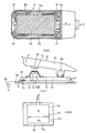
- Fig. 8 In principle, the explained acoustic coupling is shown.
- the diaphragm 54 of the loudspeaker in the housing 53 defines in said housing a first space R 1 which is coupled to the acoustic output of the hearing aid as shown at S and a second R 2 connected via one or more openings 55 to the one between encapsulation 59 and housing 53 formed space U 53 is coupled.
- Fig. 7 is a preferred embodiment of the actuating switch 31, shown in simplified and schematic.
- the actuation switch 31 comprises a toggle button 63 which is cantilevered on one side, at 65.
- the tilting bearing 65 is formed on a carriage 67, which - as shown by the double arrow F - with respect to the base housing 3 is mounted linearly displaceable. As shown schematically schematically with the spring contact 69, with respect to the base housing 3, and the bridging contact 70 on the carriage 67, the device is switched on and off by sliding the carriage back and forth via the pushbutton 63.
- a continuous groove 72 is incorporated, through which a housing-3 fixed contact pill 73 protrudes.
- resilient contact portion 75 which is preferably made as a keyboard element made of rubber-elastic, at least partially electrically conductive plastic, as known, for example, remote control keyboards.
- FIG Fig. 7 shown in dashed lines - the spring contact 69 connected to the device battery 33, the bridging contact 70 with the contact portion 75, and it acts so that the contact pill 73 as an electrical output of the switching device.
- the operation switch 31 acts both as an on / off slide switch and additionally, in an on position, as a toggle switch, which - for example, for rapid individual gain adjustment - in steps on the electronic unit 27 in accordance Fig. 1 is acted upon.
- the base housing 3 is formed by a curved, correspondingly shaped pipe part.
- this part 3 is formed in one piece, preferably made of plastic and is not as otherwise common in the construction of such hearing aids, along in Fig. 5 with M registered generatrices, separable in two shells.
- the assembly of the individual units in the basic housing 3 is given: They are simply inserted into the tube, which is much simpler than an assembly of open trays.
- Another advantage of a tubular, one-piece embodiment is its much greater stability over a split housing. As a result, a reduction of the housing wall thickness and thereby a reduction of the same is possible, or for a given external volume an increase in the usable internal volume.
- Fig. 1 With a view to Fig. 1 is apparent, in particular in the preferred one-part design of the base housing 3, that the individual units, in particular 11, 15, 27, 29 and / or 51, are assembled by axial, sequential insertion into the base housing 3. Shaping of the housing 3 with corresponding guides ensures a rapid, exact positioning, wherein the mutual electrical contacting between the electrically operated units solderless, done by means of resilient contacts. Thus, the units to be provided can be tested in advance and measured and without having to worry about an impairment after being assembled. This assembly can be easily automated.
- the overall housing with the base housing 3 and lid 19, optionally 39, is, at the joints provided with appropriate seals, easy sealable.
- the preferred embodiment of the electrical / acoustic transducer assembly 15 ensures optimum magnetic shielding of the Loudspeaker and an optimal acoustic seal with respect to structure-borne noise.
Landscapes
- Acoustics & Sound (AREA)
- General Health & Medical Sciences (AREA)
- Neurosurgery (AREA)
- Otolaryngology (AREA)
- Physics & Mathematics (AREA)
- Engineering & Computer Science (AREA)
- Signal Processing (AREA)
- Health & Medical Sciences (AREA)
- Battery Mounting, Suspending (AREA)
- Headphones And Earphones (AREA)
- Telephone Set Structure (AREA)
- Finger-Pressure Massage (AREA)
- Pharmaceuticals Containing Other Organic And Inorganic Compounds (AREA)
- Reverberation, Karaoke And Other Acoustics (AREA)
Applications Claiming Priority (1)
| Application Number | Priority Date | Filing Date | Title |
|---|---|---|---|
| PCT/CH1999/000261 WO1999043193A2 (de) | 1999-06-16 | 1999-06-16 | Hinterohr-hörgerät |
Publications (2)
| Publication Number | Publication Date |
|---|---|
| EP1183908A2 EP1183908A2 (de) | 2002-03-06 |
| EP1183908B1 true EP1183908B1 (de) | 2011-02-23 |
Family
ID=4551683
Family Applications (1)
| Application Number | Title | Priority Date | Filing Date |
|---|---|---|---|
| EP99924638A Expired - Lifetime EP1183908B1 (de) | 1999-06-16 | 1999-06-16 | Hinterohr-hörgerät |
Country Status (10)
| Country | Link |
|---|---|
| US (3) | US6625290B1 (enExample) |
| EP (1) | EP1183908B1 (enExample) |
| JP (1) | JP2002524888A (enExample) |
| CN (1) | CN1161001C (enExample) |
| AT (1) | ATE499807T1 (enExample) |
| AU (1) | AU774047B2 (enExample) |
| CA (2) | CA2634645C (enExample) |
| DE (1) | DE59915250D1 (enExample) |
| DK (1) | DK1183908T3 (enExample) |
| WO (1) | WO1999043193A2 (enExample) |
Cited By (1)
| Publication number | Priority date | Publication date | Assignee | Title |
|---|---|---|---|---|
| US10222973B2 (en) | 2014-05-30 | 2019-03-05 | Sonova Ag | Method for controlling a hearing device via touch gestures, a touch gesture controllable hearing device and a method for fitting a touch gesture controllable hearing device |
Families Citing this family (31)
| Publication number | Priority date | Publication date | Assignee | Title |
|---|---|---|---|---|
| EP1183909B1 (de) * | 1999-06-16 | 2011-02-23 | Phonak Ag | Hinterohr-hörgerät |
| CN1161001C (zh) | 1999-06-16 | 2004-08-04 | 福纳克有限公司 | 耳后助听器 |
| US7181035B2 (en) | 2000-11-22 | 2007-02-20 | Sonion Nederland B.V. | Acoustical receiver housing for hearing aids |
| US20050048996A1 (en) * | 2003-08-26 | 2005-03-03 | Cobo Rafael J. | Locking system and method for same |
| EP1463376B1 (de) * | 2004-04-13 | 2010-08-25 | Phonak Ag | Bedienelement für Hörgeräte und Hörhilfen |
| DE102004054927A1 (de) | 2004-11-13 | 2006-06-01 | Hansaton Akustik Gmbh | Hörgerät mit Lautstärkestellrad |
| WO2007011846A2 (en) * | 2005-07-18 | 2007-01-25 | Soundquest, Inc. | In-ear auditory device and methods of using same |
| US20070127757A2 (en) * | 2005-07-18 | 2007-06-07 | Soundquest, Inc. | Behind-The-Ear-Auditory Device |
| DE102006029958A1 (de) * | 2006-06-29 | 2008-01-03 | Siemens Audiologische Technik Gmbh | Modulares Hinter-dem-Ohr-Hörgerät |
| DE102007025976B3 (de) * | 2007-06-04 | 2008-11-27 | Siemens Medical Instruments Pte. Ltd. | Tragehaken mit Metallabschnitt für ein Hörgerät |
| USD584719S1 (en) * | 2007-06-22 | 2009-01-13 | Sennheiser Communications A/S | Wireless headset |
| DK2023663T3 (da) * | 2007-08-07 | 2011-05-30 | Bernafon Ag | BTE-høreapparat med udskifteligt dæksel |
| DE102007045460B3 (de) * | 2007-09-24 | 2009-06-04 | Siemens Medical Instruments Pte. Ltd. | Hörvorrichtung mit unterschiedlich gelagertem Bedienelement |
| US8121320B2 (en) * | 2008-01-11 | 2012-02-21 | Songbird Hearing, Inc. | Hearing aid |
| USD605769S1 (en) | 2008-06-26 | 2009-12-08 | Songbird Hearing, Inc. | Hearing aid part |
| USD605292S1 (en) | 2008-06-26 | 2009-12-01 | Songbird Hearing, Inc. | Hearing aid earpiece |
| NL2003672C2 (nl) | 2009-10-19 | 2011-04-20 | Exsilent Res Bv | Hoortoestel. |
| USD650080S1 (en) | 2009-11-03 | 2011-12-06 | Songbird Hearing, Inc. | Hearing aid part |
| US8331594B2 (en) * | 2010-01-08 | 2012-12-11 | Sonic Innovations, Inc. | Hearing aid device with interchangeable covers |
| USD657347S1 (en) * | 2010-12-30 | 2012-04-10 | Motorola Mobility, Inc. | Headset for a communication device |
| USD738851S1 (en) * | 2013-12-19 | 2015-09-15 | Kyocera Corporation | Portable terminal |
| US10021493B2 (en) | 2015-09-25 | 2018-07-10 | Starkey Laboratories, Inc. | Suspension assembly for hearing aid receiver |
| EP3267696A1 (en) * | 2016-07-08 | 2018-01-10 | Oticon Medical A/S | Hearing aid comprising a locking mechanism |
| JP6279779B1 (ja) * | 2017-02-13 | 2018-02-14 | リオン株式会社 | 補聴器 |
| USD838688S1 (en) * | 2017-05-07 | 2019-01-22 | Xiaoliang Liu | Wireless headset |
| AU2018203536B2 (en) * | 2017-05-23 | 2022-06-30 | Cochlear Limited | Hearing Aid Device Unit Along a Single Curved Axis |
| USD903634S1 (en) * | 2019-04-29 | 2020-12-01 | Shenzhen Quanmeng Technology Co., Ltd. | Wireless headset |
| USD903635S1 (en) * | 2020-07-09 | 2020-12-01 | Shenzhen Link Dream Electronics Co., Ltd | Earphone |
| USD944228S1 (en) * | 2021-03-16 | 2022-02-22 | Shenzhen Quanmeng Technology Co., Ltd. | Earphone |
| USD947812S1 (en) * | 2021-04-26 | 2022-04-05 | Shenzhenshi Annso Technology Co., Ltd | Wireless earphone |
| USD1025953S1 (en) * | 2022-06-08 | 2024-05-07 | Yealink (Xiamen) Network Technology Co., Ltd. | Audio headset |
Family Cites Families (16)
| Publication number | Priority date | Publication date | Assignee | Title |
|---|---|---|---|---|
| DE2346531A1 (de) * | 1973-09-15 | 1975-04-03 | Micro Technic Hueber & Co | Hoerhilfsgeraet fuer schwerhoerige oder hoerbehinderte |
| US4081782A (en) * | 1976-08-04 | 1978-03-28 | Bourns, Inc. | Combined rotary potentiometer and switch |
| CH662026A5 (de) * | 1984-02-21 | 1987-08-31 | Gfeller Ag | In-dem-ohr-hoergeraet. |
| US4617429A (en) * | 1985-02-04 | 1986-10-14 | Gaspare Bellafiore | Hearing aid |
| US4870688A (en) * | 1986-05-27 | 1989-09-26 | Barry Voroba | Mass production auditory canal hearing aid |
| US4791673A (en) * | 1986-12-04 | 1988-12-13 | Schreiber Simeon B | Bone conduction audio listening device and method |
| DE58906141D1 (de) * | 1988-07-04 | 1993-12-16 | Siemens Audiologische Technik | Hörgerät. |
| US5120922A (en) * | 1991-02-22 | 1992-06-09 | Augat Inc. | Momentary pushbutton slide switch |
| EP0589308B1 (de) * | 1992-09-23 | 1997-12-03 | Siemens Audiologische Technik GmbH | Hörgerät |
| US5463692A (en) * | 1994-07-11 | 1995-10-31 | Resistance Technology Inc. | Sandwich switch construction for a hearing aid |
| JP3431351B2 (ja) * | 1995-06-05 | 2003-07-28 | ペンタックス株式会社 | データシンボル読み取り装置 |
| US5606621A (en) * | 1995-06-14 | 1997-02-25 | Siemens Hearing Instruments, Inc. | Hybrid behind-the-ear and completely-in-canal hearing aid |
| GB2305067A (en) | 1995-09-02 | 1997-03-26 | A & M Hearing Ltd | Hearing aid having hinged housing |
| JP3911774B2 (ja) * | 1997-07-16 | 2007-05-09 | 松下電器産業株式会社 | プッシュ機構付スライドスイッチ及びその組立て方法 |
| US6009183A (en) * | 1998-06-30 | 1999-12-28 | Resound Corporation | Ambidextrous sound delivery tube system |
| CN1161001C (zh) * | 1999-06-16 | 2004-08-04 | 福纳克有限公司 | 耳后助听器 |
-
1999
- 1999-06-16 CN CNB998167312A patent/CN1161001C/zh not_active Expired - Fee Related
- 1999-06-16 DE DE59915250T patent/DE59915250D1/de not_active Expired - Lifetime
- 1999-06-16 DK DK99924638.2T patent/DK1183908T3/da active
- 1999-06-16 WO PCT/CH1999/000261 patent/WO1999043193A2/de not_active Ceased
- 1999-06-16 EP EP99924638A patent/EP1183908B1/de not_active Expired - Lifetime
- 1999-06-16 AU AU41283/99A patent/AU774047B2/en not_active Ceased
- 1999-06-16 CA CA2634645A patent/CA2634645C/en not_active Expired - Fee Related
- 1999-06-16 CA CA002377444A patent/CA2377444C/en not_active Expired - Fee Related
- 1999-06-16 AT AT99924638T patent/ATE499807T1/de active
- 1999-06-16 JP JP2000533005A patent/JP2002524888A/ja active Pending
- 1999-06-28 US US09/342,407 patent/US6625290B1/en not_active Expired - Lifetime
-
2003
- 2003-02-26 US US10/376,195 patent/US20030128857A1/en not_active Abandoned
-
2004
- 2004-09-29 US US10/953,626 patent/US7155023B2/en not_active Expired - Fee Related
Cited By (1)
| Publication number | Priority date | Publication date | Assignee | Title |
|---|---|---|---|---|
| US10222973B2 (en) | 2014-05-30 | 2019-03-05 | Sonova Ag | Method for controlling a hearing device via touch gestures, a touch gesture controllable hearing device and a method for fitting a touch gesture controllable hearing device |
Also Published As
| Publication number | Publication date |
|---|---|
| CA2634645C (en) | 2010-02-23 |
| CN1352868A (zh) | 2002-06-05 |
| DK1183908T3 (da) | 2011-06-14 |
| US7155023B2 (en) | 2006-12-26 |
| US20030128857A1 (en) | 2003-07-10 |
| ATE499807T1 (de) | 2011-03-15 |
| US6625290B1 (en) | 2003-09-23 |
| JP2002524888A (ja) | 2002-08-06 |
| US20050041826A1 (en) | 2005-02-24 |
| WO1999043193A2 (de) | 1999-09-02 |
| CA2634645A1 (en) | 1999-09-02 |
| DE59915250D1 (de) | 2011-04-07 |
| CA2377444C (en) | 2009-04-14 |
| WO1999043193A3 (de) | 2000-06-29 |
| AU4128399A (en) | 1999-09-15 |
| EP1183908A2 (de) | 2002-03-06 |
| AU774047B2 (en) | 2004-06-17 |
| CA2377444A1 (en) | 1999-09-02 |
| CN1161001C (zh) | 2004-08-04 |
Similar Documents
| Publication | Publication Date | Title |
|---|---|---|
| EP1183908B1 (de) | Hinterohr-hörgerät | |
| EP1183909B1 (de) | Hinterohr-hörgerät | |
| WO2000079835A1 (de) | Hinterohr-hörgerät | |
| WO2000079834A1 (de) | Hinterohr-hörgerät und aufsatzmodul für ein derartiges hörgerät | |
| EP1183907B1 (de) | Hinterohr-hörgerät | |
| EP0140078B1 (de) | Hörgerät mit einem hinter dem Ohr zu tragenden Gehäuse | |
| DE2939479C2 (enExample) | ||
| DE60128808T2 (de) | Ein mikrofonzusammenbau | |
| EP2070161B1 (de) | Installationsschaltgerät | |
| DE3505390C2 (de) | In-dem-Ohr-Hörgerät | |
| EP2540098B1 (de) | Konnektor für ric-bte hörgerät und ric-bte hörgerät | |
| EP0591791A1 (de) | Programmierbares Hörhilfegerät | |
| DE10343292B3 (de) | Hörgerät ohne separates Mikrofongehäuse | |
| EP0310840A1 (de) | Hörgerät mit Gehäuse | |
| EP2884771A1 (de) | HdO-Hörinstrument mit Gehäuse und Traghaken | |
| EP2144456A1 (de) | Hörhilfe mit verriegelbarem Batteriefach | |
| DE102008020926B4 (de) | Drucktaster für ein Hörgerät | |
| DE29607941U1 (de) | Hörgerät | |
| EP0466961B1 (de) | Hinter dem Ohr zu tragendes Hörhilfegerät | |
| EP0589308B1 (de) | Hörgerät | |
| CH668154A5 (en) | Hearing aid with electroacoustic transducer - fits behind ear and has facility for plugging in range of operational mode elements | |
| EP3419312B1 (de) | Hörgerät | |
| EP0609744A1 (de) | Handapparat eines schnurgebundenen Telefonapparates | |
| DE202016008901U1 (de) | Hörvorrichtung | |
| DE10039775B4 (de) | Lautsprechervorrichtung und Gerät |
Legal Events
| Date | Code | Title | Description |
|---|---|---|---|
| PUAI | Public reference made under article 153(3) epc to a published international application that has entered the european phase |
Free format text: ORIGINAL CODE: 0009012 |
|
| 17P | Request for examination filed |
Effective date: 20011120 |
|
| AK | Designated contracting states |
Kind code of ref document: A2 Designated state(s): AT BE CH CY DE DK ES FI FR GB GR IE IT LI LU MC NL PT SE |
|
| GRAP | Despatch of communication of intention to grant a patent |
Free format text: ORIGINAL CODE: EPIDOSNIGR1 |
|
| GRAS | Grant fee paid |
Free format text: ORIGINAL CODE: EPIDOSNIGR3 |
|
| GRAA | (expected) grant |
Free format text: ORIGINAL CODE: 0009210 |
|
| AK | Designated contracting states |
Kind code of ref document: B1 Designated state(s): AT BE CH CY DE DK ES FI FR GB GR IE IT LI LU MC NL PT SE |
|
| REG | Reference to a national code |
Ref country code: GB Ref legal event code: FG4D Free format text: NOT ENGLISH |
|
| REG | Reference to a national code |
Ref country code: CH Ref legal event code: NV Representative=s name: TROESCH SCHEIDEGGER WERNER AG Ref country code: CH Ref legal event code: EP |
|
| REG | Reference to a national code |
Ref country code: IE Ref legal event code: FG4D Free format text: LANGUAGE OF EP DOCUMENT: GERMAN |
|
| REF | Corresponds to: |
Ref document number: 59915250 Country of ref document: DE Date of ref document: 20110407 Kind code of ref document: P |
|
| REG | Reference to a national code |
Ref country code: DE Ref legal event code: R096 Ref document number: 59915250 Country of ref document: DE Effective date: 20110407 |
|
| REG | Reference to a national code |
Ref country code: DK Ref legal event code: T3 |
|
| REG | Reference to a national code |
Ref country code: NL Ref legal event code: VDEP Effective date: 20110223 |
|
| PG25 | Lapsed in a contracting state [announced via postgrant information from national office to epo] |
Ref country code: ES Free format text: LAPSE BECAUSE OF FAILURE TO SUBMIT A TRANSLATION OF THE DESCRIPTION OR TO PAY THE FEE WITHIN THE PRESCRIBED TIME-LIMIT Effective date: 20110603 Ref country code: GR Free format text: LAPSE BECAUSE OF FAILURE TO SUBMIT A TRANSLATION OF THE DESCRIPTION OR TO PAY THE FEE WITHIN THE PRESCRIBED TIME-LIMIT Effective date: 20110524 Ref country code: SE Free format text: LAPSE BECAUSE OF FAILURE TO SUBMIT A TRANSLATION OF THE DESCRIPTION OR TO PAY THE FEE WITHIN THE PRESCRIBED TIME-LIMIT Effective date: 20110223 Ref country code: PT Free format text: LAPSE BECAUSE OF FAILURE TO SUBMIT A TRANSLATION OF THE DESCRIPTION OR TO PAY THE FEE WITHIN THE PRESCRIBED TIME-LIMIT Effective date: 20110623 |
|
| PG25 | Lapsed in a contracting state [announced via postgrant information from national office to epo] |
Ref country code: CY Free format text: LAPSE BECAUSE OF FAILURE TO SUBMIT A TRANSLATION OF THE DESCRIPTION OR TO PAY THE FEE WITHIN THE PRESCRIBED TIME-LIMIT Effective date: 20110223 Ref country code: NL Free format text: LAPSE BECAUSE OF FAILURE TO SUBMIT A TRANSLATION OF THE DESCRIPTION OR TO PAY THE FEE WITHIN THE PRESCRIBED TIME-LIMIT Effective date: 20110223 Ref country code: FI Free format text: LAPSE BECAUSE OF FAILURE TO SUBMIT A TRANSLATION OF THE DESCRIPTION OR TO PAY THE FEE WITHIN THE PRESCRIBED TIME-LIMIT Effective date: 20110223 |
|
| REG | Reference to a national code |
Ref country code: IE Ref legal event code: FD4D |
|
| PG25 | Lapsed in a contracting state [announced via postgrant information from national office to epo] |
Ref country code: IE Free format text: LAPSE BECAUSE OF FAILURE TO SUBMIT A TRANSLATION OF THE DESCRIPTION OR TO PAY THE FEE WITHIN THE PRESCRIBED TIME-LIMIT Effective date: 20110223 |
|
| PLBE | No opposition filed within time limit |
Free format text: ORIGINAL CODE: 0009261 |
|
| STAA | Information on the status of an ep patent application or granted ep patent |
Free format text: STATUS: NO OPPOSITION FILED WITHIN TIME LIMIT |
|
| BERE | Be: lapsed |
Owner name: PHONAK A.G. Effective date: 20110630 |
|
| 26N | No opposition filed |
Effective date: 20111124 |
|
| REG | Reference to a national code |
Ref country code: DE Ref legal event code: R097 Ref document number: 59915250 Country of ref document: DE Effective date: 20111124 |
|
| PG25 | Lapsed in a contracting state [announced via postgrant information from national office to epo] |
Ref country code: BE Free format text: LAPSE BECAUSE OF NON-PAYMENT OF DUE FEES Effective date: 20110630 |
|
| PG25 | Lapsed in a contracting state [announced via postgrant information from national office to epo] |
Ref country code: IT Free format text: LAPSE BECAUSE OF FAILURE TO SUBMIT A TRANSLATION OF THE DESCRIPTION OR TO PAY THE FEE WITHIN THE PRESCRIBED TIME-LIMIT Effective date: 20110223 |
|
| REG | Reference to a national code |
Ref country code: AT Ref legal event code: MM01 Ref document number: 499807 Country of ref document: AT Kind code of ref document: T Effective date: 20110616 |
|
| PG25 | Lapsed in a contracting state [announced via postgrant information from national office to epo] |
Ref country code: AT Free format text: LAPSE BECAUSE OF NON-PAYMENT OF DUE FEES Effective date: 20110616 |
|
| PG25 | Lapsed in a contracting state [announced via postgrant information from national office to epo] |
Ref country code: MC Free format text: LAPSE BECAUSE OF NON-PAYMENT OF DUE FEES Effective date: 20110630 |
|
| PG25 | Lapsed in a contracting state [announced via postgrant information from national office to epo] |
Ref country code: LU Free format text: LAPSE BECAUSE OF NON-PAYMENT OF DUE FEES Effective date: 20110616 |
|
| REG | Reference to a national code |
Ref country code: FR Ref legal event code: PLFP Year of fee payment: 18 |
|
| REG | Reference to a national code |
Ref country code: FR Ref legal event code: PLFP Year of fee payment: 19 |
|
| PGFP | Annual fee paid to national office [announced via postgrant information from national office to epo] |
Ref country code: FR Payment date: 20170627 Year of fee payment: 19 Ref country code: CH Payment date: 20170627 Year of fee payment: 19 Ref country code: GB Payment date: 20170627 Year of fee payment: 19 Ref country code: DK Payment date: 20170626 Year of fee payment: 19 |
|
| PGFP | Annual fee paid to national office [announced via postgrant information from national office to epo] |
Ref country code: DE Payment date: 20170628 Year of fee payment: 19 |
|
| REG | Reference to a national code |
Ref country code: DE Ref legal event code: R119 Ref document number: 59915250 Country of ref document: DE |
|
| REG | Reference to a national code |
Ref country code: DK Ref legal event code: EBP Effective date: 20180630 |
|
| REG | Reference to a national code |
Ref country code: CH Ref legal event code: PL |
|
| GBPC | Gb: european patent ceased through non-payment of renewal fee |
Effective date: 20180616 |
|
| PG25 | Lapsed in a contracting state [announced via postgrant information from national office to epo] |
Ref country code: CH Free format text: LAPSE BECAUSE OF NON-PAYMENT OF DUE FEES Effective date: 20180630 Ref country code: GB Free format text: LAPSE BECAUSE OF NON-PAYMENT OF DUE FEES Effective date: 20180616 Ref country code: LI Free format text: LAPSE BECAUSE OF NON-PAYMENT OF DUE FEES Effective date: 20180630 Ref country code: FR Free format text: LAPSE BECAUSE OF NON-PAYMENT OF DUE FEES Effective date: 20180630 Ref country code: DE Free format text: LAPSE BECAUSE OF NON-PAYMENT OF DUE FEES Effective date: 20190101 |
|
| PG25 | Lapsed in a contracting state [announced via postgrant information from national office to epo] |
Ref country code: DK Free format text: LAPSE BECAUSE OF NON-PAYMENT OF DUE FEES Effective date: 20180630 |