EP1183908B1 - Behind-the-ear hearing aid - Google Patents
Behind-the-ear hearing aid Download PDFInfo
- Publication number
- EP1183908B1 EP1183908B1 EP99924638A EP99924638A EP1183908B1 EP 1183908 B1 EP1183908 B1 EP 1183908B1 EP 99924638 A EP99924638 A EP 99924638A EP 99924638 A EP99924638 A EP 99924638A EP 1183908 B1 EP1183908 B1 EP 1183908B1
- Authority
- EP
- European Patent Office
- Prior art keywords
- behind
- contact
- hearing device
- ear hearing
- hearing aid
- Prior art date
- Legal status (The legal status is an assumption and is not a legal conclusion. Google has not performed a legal analysis and makes no representation as to the accuracy of the status listed.)
- Expired - Lifetime
Links
Images

Classifications
-
- H—ELECTRICITY
- H04—ELECTRIC COMMUNICATION TECHNIQUE
- H04R—LOUDSPEAKERS, MICROPHONES, GRAMOPHONE PICK-UPS OR LIKE ACOUSTIC ELECTROMECHANICAL TRANSDUCERS; DEAF-AID SETS; PUBLIC ADDRESS SYSTEMS
- H04R25/00—Deaf-aid sets, i.e. electro-acoustic or electro-mechanical hearing aids; Electric tinnitus maskers providing an auditory perception
- H04R25/60—Mounting or interconnection of hearing aid parts, e.g. inside tips, housings or to ossicles
-
- H—ELECTRICITY
- H04—ELECTRIC COMMUNICATION TECHNIQUE
- H04R—LOUDSPEAKERS, MICROPHONES, GRAMOPHONE PICK-UPS OR LIKE ACOUSTIC ELECTROMECHANICAL TRANSDUCERS; DEAF-AID SETS; PUBLIC ADDRESS SYSTEMS
- H04R25/00—Deaf-aid sets, i.e. electro-acoustic or electro-mechanical hearing aids; Electric tinnitus maskers providing an auditory perception
-
- H—ELECTRICITY
- H01—ELECTRIC ELEMENTS
- H01H—ELECTRIC SWITCHES; RELAYS; SELECTORS; EMERGENCY PROTECTIVE DEVICES
- H01H2300/00—Orthogonal indexing scheme relating to electric switches, relays, selectors or emergency protective devices covered by H01H
- H01H2300/004—Application hearing aid
-
- H—ELECTRICITY
- H04—ELECTRIC COMMUNICATION TECHNIQUE
- H04R—LOUDSPEAKERS, MICROPHONES, GRAMOPHONE PICK-UPS OR LIKE ACOUSTIC ELECTROMECHANICAL TRANSDUCERS; DEAF-AID SETS; PUBLIC ADDRESS SYSTEMS
- H04R2225/00—Details of deaf aids covered by H04R25/00, not provided for in any of its subgroups
- H04R2225/021—Behind the ear [BTE] hearing aids
-
- H—ELECTRICITY
- H04—ELECTRIC COMMUNICATION TECHNIQUE
- H04R—LOUDSPEAKERS, MICROPHONES, GRAMOPHONE PICK-UPS OR LIKE ACOUSTIC ELECTROMECHANICAL TRANSDUCERS; DEAF-AID SETS; PUBLIC ADDRESS SYSTEMS
- H04R2225/00—Details of deaf aids covered by H04R25/00, not provided for in any of its subgroups
- H04R2225/61—Aspects relating to mechanical or electronic switches or control elements, e.g. functioning
-
- H—ELECTRICITY
- H04—ELECTRIC COMMUNICATION TECHNIQUE
- H04R—LOUDSPEAKERS, MICROPHONES, GRAMOPHONE PICK-UPS OR LIKE ACOUSTIC ELECTROMECHANICAL TRANSDUCERS; DEAF-AID SETS; PUBLIC ADDRESS SYSTEMS
- H04R25/00—Deaf-aid sets, i.e. electro-acoustic or electro-mechanical hearing aids; Electric tinnitus maskers providing an auditory perception
- H04R25/60—Mounting or interconnection of hearing aid parts, e.g. inside tips, housings or to ossicles
- H04R25/602—Mounting or interconnection of hearing aid parts, e.g. inside tips, housings or to ossicles of batteries
-
- H—ELECTRICITY
- H04—ELECTRIC COMMUNICATION TECHNIQUE
- H04R—LOUDSPEAKERS, MICROPHONES, GRAMOPHONE PICK-UPS OR LIKE ACOUSTIC ELECTROMECHANICAL TRANSDUCERS; DEAF-AID SETS; PUBLIC ADDRESS SYSTEMS
- H04R25/00—Deaf-aid sets, i.e. electro-acoustic or electro-mechanical hearing aids; Electric tinnitus maskers providing an auditory perception
- H04R25/60—Mounting or interconnection of hearing aid parts, e.g. inside tips, housings or to ossicles
- H04R25/603—Mounting or interconnection of hearing aid parts, e.g. inside tips, housings or to ossicles of mechanical or electronic switches or control elements
-
- H—ELECTRICITY
- H04—ELECTRIC COMMUNICATION TECHNIQUE
- H04R—LOUDSPEAKERS, MICROPHONES, GRAMOPHONE PICK-UPS OR LIKE ACOUSTIC ELECTROMECHANICAL TRANSDUCERS; DEAF-AID SETS; PUBLIC ADDRESS SYSTEMS
- H04R25/00—Deaf-aid sets, i.e. electro-acoustic or electro-mechanical hearing aids; Electric tinnitus maskers providing an auditory perception
- H04R25/60—Mounting or interconnection of hearing aid parts, e.g. inside tips, housings or to ossicles
- H04R25/609—Mounting or interconnection of hearing aid parts, e.g. inside tips, housings or to ossicles of circuitry
-
- H—ELECTRICITY
- H04—ELECTRIC COMMUNICATION TECHNIQUE
- H04R—LOUDSPEAKERS, MICROPHONES, GRAMOPHONE PICK-UPS OR LIKE ACOUSTIC ELECTROMECHANICAL TRANSDUCERS; DEAF-AID SETS; PUBLIC ADDRESS SYSTEMS
- H04R25/00—Deaf-aid sets, i.e. electro-acoustic or electro-mechanical hearing aids; Electric tinnitus maskers providing an auditory perception
- H04R25/65—Housing parts, e.g. shells, tips or moulds, or their manufacture
Definitions
- the present invention relates to a behind-the-ear hearing aid according to the preamble of claim 1.
- Such hearing aids are known in the art, for example from the documents EP 0 349 835 A and US 4,634,815 A ,
- the present invention aims to remedy the disadvantages mentioned.
- the hearing aid according to the invention is characterized according to the characterizing part of claim 1.
- two categories of switching functions are combined on one and the same actuating member, namely, in the mentioned positions, preferably ON / OFF switching of the hearing aid and in the second actuating direction, for example adjustment of the amplification.
- the ease of use is notably increased, it is readily possible to distinguish the two different types of actuation on a designated operating switch.
- a single operating switch provided according to the invention requires less volume and, moreover, the hearing aid as a whole becomes simpler by virtue of electrical connections to switching devices only within the scope of the invention provided an actuator must be performed.
- one of the positions is used as a switch-on position of the hearing aid, the other as a switch-off position, and the actuator acts as a toggle switch when actuated in the second direction.
- the actuating member is tilt-mounted on a slide which is displaceable in a substantially linear manner and has a contact which can be brought into contact with a device-fixed switch contact by actuation in the second direction.
- This contact is preferably made of rubber-elastic plastic, preferably hat-shaped, as is known from computer keyboard mats or remote keyboards.
- the first operating direction of the operating member is located substantially in the direction of generatrices of the device body, preferably along curvature-outer side generatrices, based on the device body deflection, and it is the second direction of actuation perpendicular to the device body wall.
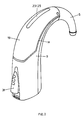
- Fig. 1 is shown in a partially simplified longitudinal section illustration of the inventive rear ear hearing aid as a whole, what initially the individual function blocks or functional parts to be described.
- the hearing aid 1 comprises a horn-shaped curved, tubular base body with a center axis A, which at the thinner, bent end, as an acoustic output, a connection piece 5 for a leading into the ear coupling pipe.
- the connecting piece 5 is replaceable on a pipe socket 9, which sits on a base housing 3, plugged or screwed.
- the inner channel 7 of the connecting piece 5 continues through the pipe socket 9 into a transmission channel 11 in the base housing 3.
- the transmission channel 11 in turn is coupled to an electrical / acoustic transducer assembly 15 in a compartment 13 of the base housing 3.
- the transmission channel 11 extends along the inner curvature of the base housing 3 such that the outside curvature side, a microphone assembly 17 finds room.
- a lid 19 is formed in this area and locked in the areas of the culmination point of the device by means of a plug-in axis 21.
- the cover 19 extends along generatrices M of the device body until, Fig. 1 ,
- the microphone assembly 17 is accessible upon removal of the hinged lid 19 and preferably only on a Flexprint tab (not shown) electrically contacted, folded over the transmission channel 11 and is located on a sound entry slot 23rd
- the insert 25 is acoustically “transparent” and has a plurality of passages between the environment U and a compensation volume V, the latter being left between the discrete microphone entry openings (not shown) and said insert.
- the insert 25 is preferably made of a sintered material, in particular of sintered material Polyethylene and thereby more preferably water repellent coated. It further forms a mesh fineness between 10 ⁇ m and 200 ⁇ m with an open porosity of preferably more than 70%.
- microphone assembly 17 and insert 25 are arranged in the slot 23 on the hearing aid 1, that they are exposed to possible hearing aid, as possible no air pressure of the environment U, by - as out Fig. 1 visible - are positioned in the region of the crest of the horn-shaped curved tubular body.
- the proposed intermediate volume V in the sense of a "common mode" suppression, that along the insert 25 differently coupled, same acoustic signals due the compensatory effect of the volume V tends to cancel.
- the insert 25 acts as a soil protection and is easy to clean thanks to their preferably water-repellent coating.
- a cylindrical flat battery or a suitably shaped battery 33 is inserted, such that the axis of the battery cylinder, with its end faces 33 u and 33 o , at least substantially, coaxial with the longitudinal axis A. of the main body lies.
- a first resilient contact 35 is provided at the base 30 of the battery compartment 29, centered in the axis A, a second 37 resiliently contacts the side surface of the battery 33.
- the battery compartment 29 can be closed by a cover 39 which is in the closed position in relation to the axis A and which is pivotally or bayonet-mounted on the base housing 3, at 41, or on the battery compartment 29.
- This transverse arrangement of the battery 33 on the hearing aid has significant advantages:
- the area closed by the lid 39 is relatively large, which, as will be explained later, can be used further.
- the battery compartment cover 39 is located at the lowest point of the device and the Deckelstossstellen to the base housing 3 are transverse to the axis A, penetration of sweat in the battery compartment is hardly critical.
- the contacts 37 and 35 are protected within the compartment, the cover 39 carries no electrical contacts. Further, because the substantially cylindrical interior of the main body 3 is utilized, there is practically no unused, lost space.
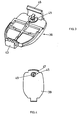
- Fig. 3 is, in perspective, a preferred embodiment of the battery cover 39 shown formed as a hinged lid.
- the Schnappscharnierteil 43 he is simply from the pivot bearing 41 according Fig. 1 unlatched or latched to it.
- it further comprises a locking lock 45, together with a resilient latch 46.
- Fig. 4 is the lid 39 according to Fig. 1 shown in external view.
- the locking lock 45 is externally operable only with a tool, such as a screwdriver, and has for this purpose, on a turntable 47, an engagement slot 49.
- the board 47 which is installed only when mounting the locking lock 45 on the hinged lid 39 is specifically colored, in two versions, eg red and blue, which this part is also used as an indication of whether the respective hearing aid is a device for left or right Ear is.
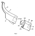
- the illustrated embodiment of the battery compartment 29, in particular the fact that the flat battery cylinder is coaxial with the axis A of the hearing aid, has a further, substantial advantage.
- Fig. 1 illustrated battery compartment, as in Fig. 5 represented, converted.
- the battery 33 is removed from the compartment and instead of the plug-in part 34 of a corresponding additional module 51 is inserted, electrically contacted to the battery contacts corresponding contact points 35a and 37a.
- the now acting as the actual battery compartment tray 29a with battery 33 is now provided on the additional module 51 and, accordingly, the lid 39, for example, removed from the base housing 3 and latched on the additional module or is engaged in a bayonet.
- a plurality of such modules 51 am in Fig. 1 illustrated basic module of the hearing aid are stacked.
- the respective fixation of the additional modules 51 is preferably carried out with a provided on the modules 51 Einrastpartie 43a, analogous to the hinge 43 on the hinged lid 39, and analogous to the snap part 46 formed on said hinged lid 39 snap part 46a or, in the bayonet lock, by appropriate insertion and twist locking.
- Fig. 6 is, simplified, the structure and storage of the mentioned arrangement 15 on the base housing 3 and in view according to Fig. 1 shown.
- the assembly 15 includes, encapsulated in a speaker housing 53, the speaker assembly (not shown) with a speaker diaphragm.
- the speaker assembly (not shown) with a speaker diaphragm.
- coupling openings the sound waves excited by the speaker diaphragm are coupled from the membrane-back space in the speaker housing 53 in the surrounding space U 53 of the speaker housing 53.
- the acoustic signals - as shown by the arrow S - to the in Fig. 1 apparent transmission channel 11 is coupled.
- the speaker housing 53 is supported on all sides in resilient, preferably in rubber-elastic bearings 57, substantially free swinging. Due to the bearings 57, the relatively large space U 53 is defined between loudspeaker housing outer wall and an encapsulation 59, which leads to a considerable increase in the bass tones.
- the membrane-rear resonance space is increased by the space U 53 many times. So that the space U 53 is acoustically fully effective, the enclosure 59 and its holder 61 are tightly connected.
- the storage volume for the speaker assembly is used optimally acoustically.
- the encapsulation 59 furthermore preferably acts as a magnetic shielding housing and is preferably made from ⁇ -metal for this purpose. It is cup-shaped and is formed on the holder 61, designed as a plastic carrier part, sealingly hooked. Between encapsulation 59, bracket 61 on the one hand and speaker housing 53 are mentioned resilient, preferably rubber-elastic, bearings 57 stretched.
- Fig. 8 In principle, the explained acoustic coupling is shown.
- the diaphragm 54 of the loudspeaker in the housing 53 defines in said housing a first space R 1 which is coupled to the acoustic output of the hearing aid as shown at S and a second R 2 connected via one or more openings 55 to the one between encapsulation 59 and housing 53 formed space U 53 is coupled.
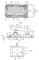
- Fig. 7 is a preferred embodiment of the actuating switch 31, shown in simplified and schematic.
- the actuation switch 31 comprises a toggle button 63 which is cantilevered on one side, at 65.
- the tilting bearing 65 is formed on a carriage 67, which - as shown by the double arrow F - with respect to the base housing 3 is mounted linearly displaceable. As shown schematically schematically with the spring contact 69, with respect to the base housing 3, and the bridging contact 70 on the carriage 67, the device is switched on and off by sliding the carriage back and forth via the pushbutton 63.
- a continuous groove 72 is incorporated, through which a housing-3 fixed contact pill 73 protrudes.
- resilient contact portion 75 which is preferably made as a keyboard element made of rubber-elastic, at least partially electrically conductive plastic, as known, for example, remote control keyboards.
- FIG Fig. 7 shown in dashed lines - the spring contact 69 connected to the device battery 33, the bridging contact 70 with the contact portion 75, and it acts so that the contact pill 73 as an electrical output of the switching device.
- the operation switch 31 acts both as an on / off slide switch and additionally, in an on position, as a toggle switch, which - for example, for rapid individual gain adjustment - in steps on the electronic unit 27 in accordance Fig. 1 is acted upon.
- the base housing 3 is formed by a curved, correspondingly shaped pipe part.
- this part 3 is formed in one piece, preferably made of plastic and is not as otherwise common in the construction of such hearing aids, along in Fig. 5 with M registered generatrices, separable in two shells.
- the assembly of the individual units in the basic housing 3 is given: They are simply inserted into the tube, which is much simpler than an assembly of open trays.
- Another advantage of a tubular, one-piece embodiment is its much greater stability over a split housing. As a result, a reduction of the housing wall thickness and thereby a reduction of the same is possible, or for a given external volume an increase in the usable internal volume.
- Fig. 1 With a view to Fig. 1 is apparent, in particular in the preferred one-part design of the base housing 3, that the individual units, in particular 11, 15, 27, 29 and / or 51, are assembled by axial, sequential insertion into the base housing 3. Shaping of the housing 3 with corresponding guides ensures a rapid, exact positioning, wherein the mutual electrical contacting between the electrically operated units solderless, done by means of resilient contacts. Thus, the units to be provided can be tested in advance and measured and without having to worry about an impairment after being assembled. This assembly can be easily automated.
- the overall housing with the base housing 3 and lid 19, optionally 39, is, at the joints provided with appropriate seals, easy sealable.
- the preferred embodiment of the electrical / acoustic transducer assembly 15 ensures optimum magnetic shielding of the Loudspeaker and an optimal acoustic seal with respect to structure-borne noise.
Abstract
Description
Die vorliegende Erfindung betrifft ein Hinterohr-Hörgerät nach dem Oberbegriff von Anspruch 1.The present invention relates to a behind-the-ear hearing aid according to the preamble of
Bei derartigen Hörgeräten ist es üblich, einen Ein-/AusSchalter vorzusehen und, davon getrennt, ein weiteres Betätigungsorgan, beispielsweise zur Einstellung der Verstärkung. Dies führt insbesondere bei Bedienung des applizierten Hörgerätes zu mühsamem Ertasten des jeweils benötigten Betätigungsorgans, ganz abgesehen davon, dass für die vorgesehenen Betätigungsorgane namhaft Bauvolumina verbraucht werden und das Vorsehen der erwähnten Organe zu einer namhaften Komplizierung des Hörgerätes mit den vorzusehenden elektrischen Verbindungen führt, somit auch zu einer erhöhten Störanfälligkeit.In such hearing aids, it is customary to provide an on / off switch and, separately, another actuator, for example, to adjust the gain. This leads in particular when operating the applied hearing aid to cumbersome palpation of the respective required actuator, quite apart from the fact that for the intended actuators namig construction volumes are consumed and the provision of the mentioned organs leads to a considerable complication of the hearing with the electrical connections to be provided, thus also to an increased susceptibility to interference.
Derartige Hörgeräte sind im Stand der Technik bekannt, beispielsweise aus den Dokumenten
Die vorliegende Erfindung bezweckt, die erwähnten Nachteile zu beheben. Zu diesen Zweck zeichnet sich das erfindungsgemässe Hörgerät nach dem Kennzeichen von Anspruch 1 aus.The present invention aims to remedy the disadvantages mentioned. For this purpose, the hearing aid according to the invention is characterized according to the characterizing part of
Mithin werden erfindungsgemäss an ein und demselben Betätigungsorgan zwei Kategorien von Schaltfunktionen kombiniert, nämlich, in den erwähnten Positionen, bevorzugt EIN-/AUSSchaltung des Hörgerätes und in zweiter Betätigungsrichtung beispielsweise Verstellung der Verstärkung. Damit wird einerseits die Bedienungsfreundlichkeit namhaft erhöht, es ist ohne weiteres möglich, am einen vorgesehenen Betätigungsschalter die beiden unterschiedlichen Betätigungsarten fühlend zu unterscheiden. Weiter benötigt ein einziger erfindungsgemäss vorgesehener Betätigungsschalter baulich weniger Volumen, und zudem wird das Hörgerät als Ganzes einfacher, indem elektrische Verbindungen zu Schaltorganen nur in den Bereich des erfindungsge-mäss vorgesehenen einen Betätigungsorgans geführt werden müssen.Thus, according to the invention, two categories of switching functions are combined on one and the same actuating member, namely, in the mentioned positions, preferably ON / OFF switching of the hearing aid and in the second actuating direction, for example adjustment of the amplification. Thus, on the one hand, the ease of use is notably increased, it is readily possible to distinguish the two different types of actuation on a designated operating switch. Furthermore, a single operating switch provided according to the invention requires less volume and, moreover, the hearing aid as a whole becomes simpler by virtue of electrical connections to switching devices only within the scope of the invention provided an actuator must be performed.
Durch Vorsehen lediglich eines mechanischen betätigbaren Organs wird auch die Störanfälligkeit reduziert und, insbesondere bei Auftreten von Störungen, die Revision wesentlich einfacher.By providing only a mechanically operable member and the susceptibility is reduced and, especially in the presence of interference, the revision much easier.
Wie erwähnt, wird in einer bevorzugten Ausführungsform die eine der Positionen als Einschaltposition des Hörgerätes, die andere als Ausschaltposition eingesetzt, und es wirkt das Betätigungsorgan bei Betätigung in zweiter Richtung als Toggelschalter. In einer weiteren bevorzugten Realisationsform ist das Betätigungsorgan an einem im wesentlichen linear verschieblichen Schieber kippgelagert und weist einen, durch Betätigung in zweiter Richtung, mit einem gerätefesten Schaltkontakt in Kontakt bringbaren Kontakt auf. Dieser Kontakt ist dabei bevorzugterweise aus gummielastischem Kunststoff gefertigt, vorzugsweise hütchenförmig, wie dies von Computertastaturmatten oder Fernbedienungstastaturen bekannt ist. Weiter bevorzugt liegt die erste Betätigungsrichtung des Bedienungsorgans im wesentlichen in Richtung von Mantellinien des Gerätekörpers, vorzugsweise entlang Krümmungs-aussenseitigen Mantellinien, bezogen auf die Gerätekörperbiegung, und es ist die zweite Betätigungsrichtung senkrecht zur Gerätekörperwandung.As mentioned, in one preferred embodiment, one of the positions is used as a switch-on position of the hearing aid, the other as a switch-off position, and the actuator acts as a toggle switch when actuated in the second direction. In a further preferred embodiment, the actuating member is tilt-mounted on a slide which is displaceable in a substantially linear manner and has a contact which can be brought into contact with a device-fixed switch contact by actuation in the second direction. This contact is preferably made of rubber-elastic plastic, preferably hat-shaped, as is known from computer keyboard mats or remote keyboards. More preferably, the first operating direction of the operating member is located substantially in the direction of generatrices of the device body, preferably along curvature-outer side generatrices, based on the device body deflection, and it is the second direction of actuation perpendicular to the device body wall.
Das erfindungsgemässe Hinterohr-Hörgerät wird anschliessend anhand von Figuren erläutert, welche eine heute bevorzugte Ausführungsform des Hinterohr-Hörgerätes zeigen. In den Figuren zeigen:
- Fig. 1
- vereinfacht, in Längsschnitt-Darstellung, ein erfin- dungsgemässes Hinterohr-Hörgerät;
- Fig. 2
- in perspektivischer Darstellung, das erfindungsgemässe Hörgerät;
- Fig. 3
- in perspektivischer Darstellung, die bevorzugte Aus- bildung eines Batteriefachdeckels am erfindungsgemä- ssen Hörgerät;
- Fig. 4
- die Aufsicht auf den Deckel gemäss
Fig. 3 mit Partien zur Links-/Rechts-Ohr-Codierung; - Fig. 5
- einerseits das Grundgehäuse des erfindungsgemässen Ge- rätes, anderseits ein bevorzugt vorgesehenes bzw. vor- sehbares Zusatzmodul, in perspektivischer Darstellung;
- Fig. 6
- in einer vergrösserten Darstellung, die elek- trisch/akustische Wandlerbaueinheit am erfindungsgemä- ssen Hörgerät gemäss
Fig. 1 ; - Fig. 7
- vereinfacht und schematisiert, ein am erfindungsgemäs- sen Gerät erfindungsgemäss vorgesehenes Betätigungsor- gan, und
- Fig. 8
- schematisch, die Einheit gemäss
Fig. 6 zur Erläuterung der akustischen Kopplungen.
- Fig. 1
- simplified, in longitudinal section illustration, a rear ear hearing aid according to the invention;
- Fig. 2
- in a perspective view, the hearing aid according to the invention;
- Fig. 3
- in a perspective view, the preferred embodiment of a battery compartment cover on the hearing aid according to the invention;
- Fig. 4
- the supervision on the cover according to
Fig. 3 with games for left / right ear coding; - Fig. 5
- on the one hand, the basic housing of the device according to the invention, on the other hand a preferably provided or foreseeable additional module, in a perspective representation;
- Fig. 6
- in an enlarged view, the electrical / acoustic transducer assembly according to the invention hearing aid according
Fig. 1 ; - Fig. 7
- simplified and schematized, an actuator provided according to the invention in accordance with the invention, and
- Fig. 8
- schematically, the unit according to
Fig. 6 to explain the acoustic couplings.
In
Der Innenkanal 7 des Anschlussstutzens 5 setzt sich durch den Rohrstutzen 9 fort in einen Übertragungskanal 11 im Grundgehäuse 3. Der Übertragungskanal 11 seinerseits ist an eine elektrisch/akustische Wandleranordnung 15 in einem Abteil 13 des Grundgehäuses 3 angekoppelt.The
Wie aus
Bei geschlossenem Deckel 19 liegen mindestens zwei vorgesehene Mikronphonöffnungen der Mikrophonbaueinheit 17 einer Einlage 25 in einem Schlitz 23 des Deckels 19 gegenüber. Die Einlage 25 ist akustisch "transparent" und weist eine Vielzahl Durchtritte zwischen der Umgebung U und einem Ausgleichsvolumen V auf, welch letzteres zwischen den (nicht dargestellten) diskreten Mikrophon-Eintrittsöffnungen und besagter Einlage freigelassen ist. Bevorzugterweise ist die Einlage 25 hierzu aus einem gesinterten Material gefertigt, wie insbesondere aus gesintertem Polyethylen und dabei weiter bevorzugt wasserabstossend beschichtet. Es bildet weiter eine Gitterfeinheit zwischen 10 µm und 200 µm mit einer Offenporigkeit bevorzugt von über 70 %. Im weiteren sind Mikrophonbaueinheit 17 und Einlage 25 im Schlitz 23 so am Hörgerät 1 angeordnet, dass sie, bei getragenem Hörgerät, möglichst keinem Luftstaudruck der Umgebung U ausgesetzt sind, indem sie - wie aus
Im weiteren wirkt die Einlage 25 als Verschmutzungsschutz und ist dank ihrer bevorzugt wasserabstossenden Beschichtung leicht reinigbar.In addition, the
Ein weiterer Vorteil der Einlage 25 mit ihrer Vielzahl von Durchtritten ist - eng gekoppelt an den Aspekt der oben erwähnten "common mode"-Unterdrückung - dass sich eine allfällige Verschmutzung auf beide Mikrophone gleich auswirkt und dadurch keine Verschlechterung der Richtwirkung (Richtcharakteristik) entsteht, was bei konventionellen Richtmikrophonen mit zwei und mehr diskreten Öffnungen ein zentrales Problem darstellt.Another advantage of the
Bezüglich dieser Einlage 25 und ihrer Wirkungen wird auch auf die
In das in das Grundgehäuse 3 endständig eingelegte Batteriefach 29 wird eine zylinderförmige Flachbatterie bzw. ein entsprechend geformter Akku 33 eingelegt, derart, dass die Achse des Batterie-Zylinders, mit seinen Stirnflächen 33u und 33o, mindestens im wesentlichen, koaxial zur Längsachse A des Grundkörpers liegt.In the
An der Basis 30 des Batteriefaches 29, zentriert in der Achse A, ist ein erster federnder Kontakt 35 vorgesehen, ein zweiter 37 tritt federnd mit der Seitenfläche der Batterie 33 in Kontakt. Das Batteriefach 29 ist mit einem in geschlossener Position zur Achse A querstehenden Deckel 39 verschliessbar, welcher am Grundgehäuse 3, bei 41, schwenk- oder bajonettgelagert ist oder am Batteriefach 29.At the
Dieses querliegende Anordnen der Batterie 33 am Hörgerät weist wesentliche Vorteile auf: Die durch den Deckel 39 verschlossene Fläche ist relativ gross, was - wie noch auszuführen sein wird - weiter genutzt werden kann. Weil weiter der Batteriefach-Deckel 39 am tiefsten Ort des Gerätes angeordnet ist und die Deckelstossstellen zum Grundgehäuse 3 quer zur Achse A liegen, ist ein Eindringen von Schweiss in das Batteriefach kaum kritisch. Im weiteren sind bei dieser Batteriefach-Ausbildung die Kontakte 37 und 35 innerhalb des Faches geschützt, der Deckel 39 trägt keine elektrischen Kontakte. Weil weiter der im wesentlichen zylindrische Innenraum des Grundkörpers 3 ausgenützt wird, ergibt sich praktisch kein nicht genutzter, verlorener Raum.This transverse arrangement of the
In
In
Wie erwähnt wurde, hat die dargestellte Ausführungsform des Batteriefachs 29, insbesondere die Tatsache, dass der Batterie-Flachzylinder koaxial zur Achse A des Hörgerätes liegt, einen weiteren, wesentlichen Vorteil. Das in
Es ist oft erwünscht, diese Grundkonfiguration mit Zusatzoptionen auszurüsten, beispielsweise mit einer Schnittstelleneinheit für drahtlose Signalübertragung, einer Programmiersteckereinheit, einem weiteren Audioeingang, einem grösseren Akkumulatorfach, einer mechanischen Betätigungseinheit etc. Hierzu wird das in
Im Hinblick auf den Einsatz solcher Zusatzmodule ist es durchaus möglich, im Fach 29 weitere Kontakte vorzusehen.With regard to the use of such additional modules, it is quite possible to provide in
Das nun als eigentliches Batteriefach wirkende Fach 29a mit Batterie 33 ist nun am Zusatzmodul 51 vorgesehen und, entsprechend, der Deckel 39, der z.B. vom Grundgehäuse 3 entfernt und am Zusatzmodul eingeklinkt oder bajonettartig eingerastet wird. Gegebenenfalls können mehrere derartige Module 51 am in
Damit ist es möglich, das Hörgerät auf höchst einfache Art und Weise modular den Wünschen entsprechend auszubauen, Batterie bzw. Akkumulator 33 bleiben immer ohne weiteres von aussen zugänglich.This makes it possible to expand the hearing aid in a very simple manner according to the wishes, battery or
In
Das Lautsprechergehäuse 53 ist allseits in federnden, vorzugsweise in gummielastischen Lagerungen 57, im wesentlichen frei schwingend gehaltert. Durch die Lagerungen 57 wird zwischen Lautsprechergehäuse-Aussenwand und einer Kapselung 59 der relativ grosse Raum U53 definiert, welcher zu einer namhaften Anhebung der Tieftöne führt. Der membranrückseitige Resonanzraum wird durch den Raum U53 um ein Vielfaches vergrössert. Damit der Raum U53 akustisch vollumfänglich wirksam ist, sind die Kapselung 59 und ihre Halterung 61 dicht verbunden.The
Damit wird das Lagerungsvolumen für die Lautsprecheranordnung akustisch optimal genutzt. Die Kapselung 59 wirkt weiter bevorzugterweise als magnetisches Schirmungsgehäuse und ist hierzu bevorzugt aus µ-Metall gefertigt. Sie ist becherförmig ausgebildet und ist an der Halterung 61, als Kunststoffträgerteil ausgebildet, dichtend eingehakt. Zwischen Kapselung 59, Halterung 61 einerseits und Lautsprechergehäuse 53 sind die erwähnten federnden, vorzugsweise gummielastischen, Lagerungen 57 gespannt.Thus, the storage volume for the speaker assembly is used optimally acoustically. The
In
In
Das Kipplager 65 ist an einem Schlitten 67 angeformt, welcher - wie mit dem Doppelpfeil F dargestellt - bezüglich des Grundgehäuses 3 linear verschieblich gelagert ist. Wie schematisch mit dem Federkontakt 69, bezüglich des Grundgehäuses 3 fix, und dem Überbrückungskontakt 70 am Schlitten 67 dargestellt, wird durch hin und her Schieben des Schlittens über Taster 63 das Gerät ein- und ausgeschaltet.The tilting
Im Schlitten 67 ist eine durchgehende Nut 72 eingearbeitet, durch welche eine Gehäuse-3-feste Kontaktpille 73 durchragt. Diese ist überdeckt durch eine am Schlitten 67 angeordnete federnde Kontaktpartie 75, welche bevorzugterweise als Tastaturelement aus gummielastischem, mindestens teilweise elektrisch leitendem Kunststoff gefertigt ist, wie bekannt beispielsweise von Fernbedienungstastaturen. Bei kippender Betätigung des Kipptasters 63 - wie mit dem Doppelpfeil K dargestellt - tritt die Kontaktpartie 75 mit der Kontaktpille 73 in Kontakt und erstellt zwischen diesen Elementen eine elektrische Verbindung. Obwohl sich für den Fachmann eine Vielzahl möglicher elektrischer Verbindungen unter Einschluss der Schaltstrecke S1, betätigt durch die Schlittenbewegung F, und der Schaltstrecke S2, betätigt durch die Kippbewegung K des Kipptasters 63, ergibt, ist bevorzugterweise - wie in
Damit wirkt der Betätigungsschalter 31 sowohl als Ein-/Aus-Schiebeschalter und zusätzlich, in Ein-Position, als Toggelschalter, womit - beispielsweise zur raschen individuellen Verstärkungseinstellung - in Schritten auf die Elektronikeinheit 27 gemäss
Mit dem Betätigungsschalter 31 werden mithin zwei Funktionen kombiniert, Schiebeschalter und Toggelschalter, eine Funktionsverschmelzung, die insbesondere für das erfindungsgemässe Hinterohrgerät höchst vorteilhaft ist. Die Bedienungsunterschiedlichkeit sichert, dass keine Funktionsverwechslung stattfindet, was bei Vorsehen zweier Schalter für die erwähnten beiden Funktionen wesentlich kritischer ist.Thus, two functions are combined with the
Wie sich insbesondere aus
Mit Blick auf
Die bevorzugte Ausführung der elektrisch/akustischen Wandleranordnung 15 sichert eine optimale magnetische Abschirmung der Lautsprecher und eine optimale akustische Abdichtung bezüglich Körperschall.The preferred embodiment of the electrical /
Claims (5)
- A behind-the-ear hearing device with a hook-shaped curved device body, substantially extending along a likewise curved longitudinal device axis (A), in which an acoustic/electric transducer (17), an electric/acoustic transducer (15) and an electronic unit (27) are integrated, further with a manual control member provided at the device body, characterised in that the manual control member (31) is moveable effective for electrical switching in a first actuating direction (F) into at least a first and second position, and in at least one of the positions is moveable effective for switching in a further actuating direction (K).
- The behind-the-ear hearing device of claim 1, characterised in that at least one of the positions is the on position of the hearing device and another position is the off position, and in that the manual control member (31) acts as a toggle switch when actuated in the second direction (K).
- The behind-the-ear hearing device of claim 1 or 2, characterised in that the manual control member (31) is tiltably mounted (65) on a substantially linearly displaceable slider (67) and features a contact (75) which by actuation in the second direction (K) can be brought into contact with a switching contact (73) fixed on the hearing device.
- The behind-the-ear hearing device of claim 3, characterised in that the contact (75) which can be brought into contact with the switching contact fixed on the hearing device is made of rubber-elastic plastic, preferably in the shape of a small hat.
- The behind-the-ear hearing device of one of the claims 1 to 4, characterised in that the first actuating direction (F) substantially extends in the direction of surface lines (M) of the device body, preferably along surface lines with an outward curvature, the second actuating direction (K) being perpendicular to the wall of the device body.
Applications Claiming Priority (1)
| Application Number | Priority Date | Filing Date | Title |
|---|---|---|---|
| PCT/CH1999/000261 WO1999043193A2 (en) | 1999-06-16 | 1999-06-16 | Behind-the-ear hearing aid |
Publications (2)
| Publication Number | Publication Date |
|---|---|
| EP1183908A2 EP1183908A2 (en) | 2002-03-06 |
| EP1183908B1 true EP1183908B1 (en) | 2011-02-23 |
Family
ID=4551683
Family Applications (1)
| Application Number | Title | Priority Date | Filing Date |
|---|---|---|---|
| EP99924638A Expired - Lifetime EP1183908B1 (en) | 1999-06-16 | 1999-06-16 | Behind-the-ear hearing aid |
Country Status (10)
| Country | Link |
|---|---|
| US (3) | US6625290B1 (en) |
| EP (1) | EP1183908B1 (en) |
| JP (1) | JP2002524888A (en) |
| CN (1) | CN1161001C (en) |
| AT (1) | ATE499807T1 (en) |
| AU (1) | AU774047B2 (en) |
| CA (2) | CA2377444C (en) |
| DE (1) | DE59915250D1 (en) |
| DK (1) | DK1183908T3 (en) |
| WO (1) | WO1999043193A2 (en) |
Cited By (1)
| Publication number | Priority date | Publication date | Assignee | Title |
|---|---|---|---|---|
| US10222973B2 (en) | 2014-05-30 | 2019-03-05 | Sonova Ag | Method for controlling a hearing device via touch gestures, a touch gesture controllable hearing device and a method for fitting a touch gesture controllable hearing device |
Families Citing this family (25)
| Publication number | Priority date | Publication date | Assignee | Title |
|---|---|---|---|---|
| DE59915250D1 (en) | 1999-06-16 | 2011-04-07 | Phonak Ag | BEHIND EAR HEARING AID |
| JP2002537665A (en) * | 1999-06-16 | 2002-11-05 | フォーナック アーゲー | Hearing aid mounted behind the ear and method of assembling the same |
| US7181035B2 (en) | 2000-11-22 | 2007-02-20 | Sonion Nederland B.V. | Acoustical receiver housing for hearing aids |
| US20050048996A1 (en) * | 2003-08-26 | 2005-03-03 | Cobo Rafael J. | Locking system and method for same |
| DE502004011569D1 (en) * | 2004-04-13 | 2010-10-07 | Phonak Ag | Operating element for hearing aids and hearing aids |
| DE102004054927A1 (en) * | 2004-11-13 | 2006-06-01 | Hansaton Akustik Gmbh | Hearing aid with volume control wheel |
| WO2007011846A2 (en) * | 2005-07-18 | 2007-01-25 | Soundquest, Inc. | In-ear auditory device and methods of using same |
| US20070127757A2 (en) * | 2005-07-18 | 2007-06-07 | Soundquest, Inc. | Behind-The-Ear-Auditory Device |
| DE102006029958A1 (en) * | 2006-06-29 | 2008-01-03 | Siemens Audiologische Technik Gmbh | Modular behind-the-ear hearing aid |
| DE102007025976B3 (en) * | 2007-06-04 | 2008-11-27 | Siemens Medical Instruments Pte. Ltd. | Carrying hook with metal section for a hearing aid |
| DE602007012685D1 (en) * | 2007-08-07 | 2011-04-07 | Bernafon Ag | Behind-the-ear hearing aid with exchangeable housing plate |
| DE102007045460B3 (en) * | 2007-09-24 | 2009-06-04 | Siemens Medical Instruments Pte. Ltd. | Hearing device with differently mounted control |
| US8121320B2 (en) * | 2008-01-11 | 2012-02-21 | Songbird Hearing, Inc. | Hearing aid |
| NL2003672C2 (en) | 2009-10-19 | 2011-04-20 | Exsilent Res Bv | HEARING DEVICE. |
| US8331594B2 (en) * | 2010-01-08 | 2012-12-11 | Sonic Innovations, Inc. | Hearing aid device with interchangeable covers |
| USD738851S1 (en) * | 2013-12-19 | 2015-09-15 | Kyocera Corporation | Portable terminal |
| US10021493B2 (en) | 2015-09-25 | 2018-07-10 | Starkey Laboratories, Inc. | Suspension assembly for hearing aid receiver |
| EP3267696A1 (en) * | 2016-07-08 | 2018-01-10 | Oticon Medical A/S | Hearing aid comprising a locking mechanism |
| JP6279779B1 (en) * | 2017-02-13 | 2018-02-14 | リオン株式会社 | hearing aid |
| USD838688S1 (en) * | 2017-05-07 | 2019-01-22 | Xiaoliang Liu | Wireless headset |
| AU2018203536B2 (en) * | 2017-05-23 | 2022-06-30 | Oticon Medical A/S | Hearing Aid Device Unit Along a Single Curved Axis |
| USD903634S1 (en) * | 2019-04-29 | 2020-12-01 | Shenzhen Quanmeng Technology Co., Ltd. | Wireless headset |
| USD903635S1 (en) * | 2020-07-09 | 2020-12-01 | Shenzhen Link Dream Electronics Co., Ltd | Earphone |
| USD944228S1 (en) * | 2021-03-16 | 2022-02-22 | Shenzhen Quanmeng Technology Co., Ltd. | Earphone |
| USD947812S1 (en) * | 2021-04-26 | 2022-04-05 | Shenzhenshi Annso Technology Co., Ltd | Wireless earphone |
Family Cites Families (16)
| Publication number | Priority date | Publication date | Assignee | Title |
|---|---|---|---|---|
| DE2346531A1 (en) * | 1973-09-15 | 1975-04-03 | Micro Technic Hueber & Co | Hearing aid with directional microphone - has device converting microphone lobe characteristic into spherical characteristic |
| US4081782A (en) * | 1976-08-04 | 1978-03-28 | Bourns, Inc. | Combined rotary potentiometer and switch |
| CH662026A5 (en) * | 1984-02-21 | 1987-08-31 | Gfeller Ag | IN-THE-EAR HOER DEVICE. |
| US4617429A (en) * | 1985-02-04 | 1986-10-14 | Gaspare Bellafiore | Hearing aid |
| US4870688A (en) * | 1986-05-27 | 1989-09-26 | Barry Voroba | Mass production auditory canal hearing aid |
| US4791673A (en) * | 1986-12-04 | 1988-12-13 | Schreiber Simeon B | Bone conduction audio listening device and method |
| EP0349835B1 (en) * | 1988-07-04 | 1993-11-10 | Siemens Audiologische Technik GmbH | Hearing aid |
| US5120922A (en) * | 1991-02-22 | 1992-06-09 | Augat Inc. | Momentary pushbutton slide switch |
| DE59307773D1 (en) * | 1992-09-23 | 1998-01-15 | Siemens Audiologische Technik | Hearing aid |
| US5463692A (en) * | 1994-07-11 | 1995-10-31 | Resistance Technology Inc. | Sandwich switch construction for a hearing aid |
| JP3431351B2 (en) * | 1995-06-05 | 2003-07-28 | ペンタックス株式会社 | Data symbol reading device |
| US5606621A (en) * | 1995-06-14 | 1997-02-25 | Siemens Hearing Instruments, Inc. | Hybrid behind-the-ear and completely-in-canal hearing aid |
| GB2305067A (en) | 1995-09-02 | 1997-03-26 | A & M Hearing Ltd | Hearing aid having hinged housing |
| JP3911774B2 (en) * | 1997-07-16 | 2007-05-09 | 松下電器産業株式会社 | Slide switch with push mechanism and assembly method thereof |
| US6009183A (en) * | 1998-06-30 | 1999-12-28 | Resound Corporation | Ambidextrous sound delivery tube system |
| DE59915250D1 (en) * | 1999-06-16 | 2011-04-07 | Phonak Ag | BEHIND EAR HEARING AID |
-
1999
- 1999-06-16 DE DE59915250T patent/DE59915250D1/en not_active Expired - Lifetime
- 1999-06-16 CN CNB998167312A patent/CN1161001C/en not_active Expired - Fee Related
- 1999-06-16 WO PCT/CH1999/000261 patent/WO1999043193A2/en active IP Right Grant
- 1999-06-16 EP EP99924638A patent/EP1183908B1/en not_active Expired - Lifetime
- 1999-06-16 CA CA002377444A patent/CA2377444C/en not_active Expired - Fee Related
- 1999-06-16 AU AU41283/99A patent/AU774047B2/en not_active Ceased
- 1999-06-16 AT AT99924638T patent/ATE499807T1/en active
- 1999-06-16 CA CA2634645A patent/CA2634645C/en not_active Expired - Fee Related
- 1999-06-16 DK DK99924638.2T patent/DK1183908T3/en active
- 1999-06-16 JP JP2000533005A patent/JP2002524888A/en active Pending
- 1999-06-28 US US09/342,407 patent/US6625290B1/en not_active Expired - Lifetime
-
2003
- 2003-02-26 US US10/376,195 patent/US20030128857A1/en not_active Abandoned
-
2004
- 2004-09-29 US US10/953,626 patent/US7155023B2/en not_active Expired - Fee Related
Cited By (1)
| Publication number | Priority date | Publication date | Assignee | Title |
|---|---|---|---|---|
| US10222973B2 (en) | 2014-05-30 | 2019-03-05 | Sonova Ag | Method for controlling a hearing device via touch gestures, a touch gesture controllable hearing device and a method for fitting a touch gesture controllable hearing device |
Also Published As
| Publication number | Publication date |
|---|---|
| EP1183908A2 (en) | 2002-03-06 |
| WO1999043193A2 (en) | 1999-09-02 |
| AU4128399A (en) | 1999-09-15 |
| CA2634645A1 (en) | 1999-09-02 |
| AU774047B2 (en) | 2004-06-17 |
| WO1999043193A3 (en) | 2000-06-29 |
| DE59915250D1 (en) | 2011-04-07 |
| CA2377444A1 (en) | 1999-09-02 |
| JP2002524888A (en) | 2002-08-06 |
| US6625290B1 (en) | 2003-09-23 |
| US20050041826A1 (en) | 2005-02-24 |
| DK1183908T3 (en) | 2011-06-14 |
| US7155023B2 (en) | 2006-12-26 |
| CN1161001C (en) | 2004-08-04 |
| ATE499807T1 (en) | 2011-03-15 |
| CN1352868A (en) | 2002-06-05 |
| CA2377444C (en) | 2009-04-14 |
| CA2634645C (en) | 2010-02-23 |
| US20030128857A1 (en) | 2003-07-10 |
Similar Documents
| Publication | Publication Date | Title |
|---|---|---|
| EP1183908B1 (en) | Behind-the-ear hearing aid | |
| EP1183909B1 (en) | Behind-the-ear hearing aid | |
| WO2000079835A1 (en) | Hearing-aid, worn behind the ear | |
| WO2000079834A1 (en) | Hearing aid worn behind the ear and plug-in module for a hearing aid of this type | |
| EP1183907B1 (en) | Hearing-aid, worn behind the ear | |
| EP0140078B1 (en) | Hearing aid having a housing to be worn behind the ear | |
| DE2939479C2 (en) | ||
| DE60128808T2 (en) | A MICROPHONE ASSEMBLY | |
| EP2070161B1 (en) | Installation switching device | |
| DE3505390C2 (en) | In-the-ear hearing aid | |
| EP2540098B1 (en) | Connector for a ric-bte hearing instrument and ric-bte hearing instrument | |
| EP0129788B1 (en) | Hearing aid | |
| EP0136643A2 (en) | Hearing aid | |
| DE10343292B3 (en) | Hearing aid e.g. for hearing impaired people, without separate microphone housing, has hearing aid housing and a microphone housing which are formed from a one-piece with housing having cover for acoustic isolation | |
| EP2112672A2 (en) | Pushbutton for a hearing aid | |
| EP3197180B1 (en) | Hearing aid | |
| EP2144456A1 (en) | Hearing aid with lockable battery chamber | |
| DE4121311C1 (en) | ||
| EP0466961B1 (en) | Hearing aid apparatus to be worn behind the ear | |
| EP0589308B1 (en) | Hearing aid | |
| CH668154A5 (en) | Hearing aid with electroacoustic transducer - fits behind ear and has facility for plugging in range of operational mode elements | |
| DE102017210448B3 (en) | hearing Aid | |
| EP0609744A1 (en) | Handset for corded telephone apparatus | |
| EP2375783B1 (en) | Hearing device with audio shoe | |
| DE10039775B4 (en) | Loudspeaker device and device |
Legal Events
| Date | Code | Title | Description |
|---|---|---|---|
| PUAI | Public reference made under article 153(3) epc to a published international application that has entered the european phase |
Free format text: ORIGINAL CODE: 0009012 |
|
| 17P | Request for examination filed |
Effective date: 20011120 |
|
| AK | Designated contracting states |
Kind code of ref document: A2 Designated state(s): AT BE CH CY DE DK ES FI FR GB GR IE IT LI LU MC NL PT SE |
|
| GRAP | Despatch of communication of intention to grant a patent |
Free format text: ORIGINAL CODE: EPIDOSNIGR1 |
|
| GRAS | Grant fee paid |
Free format text: ORIGINAL CODE: EPIDOSNIGR3 |
|
| GRAA | (expected) grant |
Free format text: ORIGINAL CODE: 0009210 |
|
| AK | Designated contracting states |
Kind code of ref document: B1 Designated state(s): AT BE CH CY DE DK ES FI FR GB GR IE IT LI LU MC NL PT SE |
|
| REG | Reference to a national code |
Ref country code: GB Ref legal event code: FG4D Free format text: NOT ENGLISH |
|
| REG | Reference to a national code |
Ref country code: CH Ref legal event code: NV Representative=s name: TROESCH SCHEIDEGGER WERNER AG Ref country code: CH Ref legal event code: EP |
|
| REG | Reference to a national code |
Ref country code: IE Ref legal event code: FG4D Free format text: LANGUAGE OF EP DOCUMENT: GERMAN |
|
| REF | Corresponds to: |
Ref document number: 59915250 Country of ref document: DE Date of ref document: 20110407 Kind code of ref document: P |
|
| REG | Reference to a national code |
Ref country code: DE Ref legal event code: R096 Ref document number: 59915250 Country of ref document: DE Effective date: 20110407 |
|
| REG | Reference to a national code |
Ref country code: DK Ref legal event code: T3 |
|
| REG | Reference to a national code |
Ref country code: NL Ref legal event code: VDEP Effective date: 20110223 |
|
| PG25 | Lapsed in a contracting state [announced via postgrant information from national office to epo] |
Ref country code: ES Free format text: LAPSE BECAUSE OF FAILURE TO SUBMIT A TRANSLATION OF THE DESCRIPTION OR TO PAY THE FEE WITHIN THE PRESCRIBED TIME-LIMIT Effective date: 20110603 Ref country code: GR Free format text: LAPSE BECAUSE OF FAILURE TO SUBMIT A TRANSLATION OF THE DESCRIPTION OR TO PAY THE FEE WITHIN THE PRESCRIBED TIME-LIMIT Effective date: 20110524 Ref country code: SE Free format text: LAPSE BECAUSE OF FAILURE TO SUBMIT A TRANSLATION OF THE DESCRIPTION OR TO PAY THE FEE WITHIN THE PRESCRIBED TIME-LIMIT Effective date: 20110223 Ref country code: PT Free format text: LAPSE BECAUSE OF FAILURE TO SUBMIT A TRANSLATION OF THE DESCRIPTION OR TO PAY THE FEE WITHIN THE PRESCRIBED TIME-LIMIT Effective date: 20110623 |
|
| PG25 | Lapsed in a contracting state [announced via postgrant information from national office to epo] |
Ref country code: CY Free format text: LAPSE BECAUSE OF FAILURE TO SUBMIT A TRANSLATION OF THE DESCRIPTION OR TO PAY THE FEE WITHIN THE PRESCRIBED TIME-LIMIT Effective date: 20110223 Ref country code: NL Free format text: LAPSE BECAUSE OF FAILURE TO SUBMIT A TRANSLATION OF THE DESCRIPTION OR TO PAY THE FEE WITHIN THE PRESCRIBED TIME-LIMIT Effective date: 20110223 Ref country code: FI Free format text: LAPSE BECAUSE OF FAILURE TO SUBMIT A TRANSLATION OF THE DESCRIPTION OR TO PAY THE FEE WITHIN THE PRESCRIBED TIME-LIMIT Effective date: 20110223 |
|
| REG | Reference to a national code |
Ref country code: IE Ref legal event code: FD4D |
|
| PG25 | Lapsed in a contracting state [announced via postgrant information from national office to epo] |
Ref country code: IE Free format text: LAPSE BECAUSE OF FAILURE TO SUBMIT A TRANSLATION OF THE DESCRIPTION OR TO PAY THE FEE WITHIN THE PRESCRIBED TIME-LIMIT Effective date: 20110223 |
|
| PLBE | No opposition filed within time limit |
Free format text: ORIGINAL CODE: 0009261 |
|
| STAA | Information on the status of an ep patent application or granted ep patent |
Free format text: STATUS: NO OPPOSITION FILED WITHIN TIME LIMIT |
|
| BERE | Be: lapsed |
Owner name: PHONAK A.G. Effective date: 20110630 |
|
| 26N | No opposition filed |
Effective date: 20111124 |
|
| REG | Reference to a national code |
Ref country code: DE Ref legal event code: R097 Ref document number: 59915250 Country of ref document: DE Effective date: 20111124 |
|
| PG25 | Lapsed in a contracting state [announced via postgrant information from national office to epo] |
Ref country code: BE Free format text: LAPSE BECAUSE OF NON-PAYMENT OF DUE FEES Effective date: 20110630 |
|
| PG25 | Lapsed in a contracting state [announced via postgrant information from national office to epo] |
Ref country code: IT Free format text: LAPSE BECAUSE OF FAILURE TO SUBMIT A TRANSLATION OF THE DESCRIPTION OR TO PAY THE FEE WITHIN THE PRESCRIBED TIME-LIMIT Effective date: 20110223 |
|
| REG | Reference to a national code |
Ref country code: AT Ref legal event code: MM01 Ref document number: 499807 Country of ref document: AT Kind code of ref document: T Effective date: 20110616 |
|
| PG25 | Lapsed in a contracting state [announced via postgrant information from national office to epo] |
Ref country code: AT Free format text: LAPSE BECAUSE OF NON-PAYMENT OF DUE FEES Effective date: 20110616 |
|
| PG25 | Lapsed in a contracting state [announced via postgrant information from national office to epo] |
Ref country code: MC Free format text: LAPSE BECAUSE OF NON-PAYMENT OF DUE FEES Effective date: 20110630 |
|
| PG25 | Lapsed in a contracting state [announced via postgrant information from national office to epo] |
Ref country code: LU Free format text: LAPSE BECAUSE OF NON-PAYMENT OF DUE FEES Effective date: 20110616 |
|
| REG | Reference to a national code |
Ref country code: FR Ref legal event code: PLFP Year of fee payment: 18 |
|
| REG | Reference to a national code |
Ref country code: FR Ref legal event code: PLFP Year of fee payment: 19 |
|
| PGFP | Annual fee paid to national office [announced via postgrant information from national office to epo] |
Ref country code: FR Payment date: 20170627 Year of fee payment: 19 Ref country code: CH Payment date: 20170627 Year of fee payment: 19 Ref country code: GB Payment date: 20170627 Year of fee payment: 19 Ref country code: DK Payment date: 20170626 Year of fee payment: 19 |
|
| PGFP | Annual fee paid to national office [announced via postgrant information from national office to epo] |
Ref country code: DE Payment date: 20170628 Year of fee payment: 19 |
|
| REG | Reference to a national code |
Ref country code: DE Ref legal event code: R119 Ref document number: 59915250 Country of ref document: DE |
|
| REG | Reference to a national code |
Ref country code: DK Ref legal event code: EBP Effective date: 20180630 |
|
| REG | Reference to a national code |
Ref country code: CH Ref legal event code: PL |
|
| GBPC | Gb: european patent ceased through non-payment of renewal fee |
Effective date: 20180616 |
|
| PG25 | Lapsed in a contracting state [announced via postgrant information from national office to epo] |
Ref country code: CH Free format text: LAPSE BECAUSE OF NON-PAYMENT OF DUE FEES Effective date: 20180630 Ref country code: GB Free format text: LAPSE BECAUSE OF NON-PAYMENT OF DUE FEES Effective date: 20180616 Ref country code: LI Free format text: LAPSE BECAUSE OF NON-PAYMENT OF DUE FEES Effective date: 20180630 Ref country code: FR Free format text: LAPSE BECAUSE OF NON-PAYMENT OF DUE FEES Effective date: 20180630 Ref country code: DE Free format text: LAPSE BECAUSE OF NON-PAYMENT OF DUE FEES Effective date: 20190101 |
|
| PG25 | Lapsed in a contracting state [announced via postgrant information from national office to epo] |
Ref country code: DK Free format text: LAPSE BECAUSE OF NON-PAYMENT OF DUE FEES Effective date: 20180630 |