EP1183525B1 - Verfahren zur detektion des von einer probe kommenden lichtes - Google Patents
Verfahren zur detektion des von einer probe kommenden lichtes Download PDFInfo
- Publication number
- EP1183525B1 EP1183525B1 EP01919284A EP01919284A EP1183525B1 EP 1183525 B1 EP1183525 B1 EP 1183525B1 EP 01919284 A EP01919284 A EP 01919284A EP 01919284 A EP01919284 A EP 01919284A EP 1183525 B1 EP1183525 B1 EP 1183525B1
- Authority
- EP
- European Patent Office
- Prior art keywords
- sample
- fcs
- image
- scanning
- control unit
- Prior art date
- Legal status (The legal status is an assumption and is not a legal conclusion. Google has not performed a legal analysis and makes no representation as to the accuracy of the status listed.)
- Revoked
Links
- 238000000034 method Methods 0.000 title claims description 19
- 238000004458 analytical method Methods 0.000 claims abstract description 13
- 230000004001 molecular interaction Effects 0.000 claims abstract description 5
- 238000002060 fluorescence correlation spectroscopy Methods 0.000 claims description 39
- 238000001514 detection method Methods 0.000 claims description 13
- 238000011156 evaluation Methods 0.000 claims description 11
- 238000005259 measurement Methods 0.000 claims description 11
- 230000008569 process Effects 0.000 claims description 7
- 238000004621 scanning probe microscopy Methods 0.000 claims description 2
- 238000006073 displacement reaction Methods 0.000 claims 2
- 238000005286 illumination Methods 0.000 claims 1
- 238000003384 imaging method Methods 0.000 abstract description 6
- 238000000386 microscopy Methods 0.000 description 3
- 230000008901 benefit Effects 0.000 description 2
- 238000010276 construction Methods 0.000 description 2
- 238000005100 correlation spectroscopy Methods 0.000 description 2
- 238000009792 diffusion process Methods 0.000 description 2
- 238000009826 distribution Methods 0.000 description 2
- 238000011835 investigation Methods 0.000 description 2
- 101000737578 Arabidopsis thaliana Bifunctional cystathionine gamma-lyase/cysteine synthase Proteins 0.000 description 1
- 101000952234 Homo sapiens Sphingolipid delta(4)-desaturase DES1 Proteins 0.000 description 1
- 102100037416 Sphingolipid delta(4)-desaturase DES1 Human genes 0.000 description 1
- 239000003086 colorant Substances 0.000 description 1
- 230000005284 excitation Effects 0.000 description 1
- 238000002073 fluorescence micrograph Methods 0.000 description 1
- 238000000799 fluorescence microscopy Methods 0.000 description 1
- 230000006870 function Effects 0.000 description 1
- 238000001119 image correlation spectroscopy Methods 0.000 description 1
- 230000003993 interaction Effects 0.000 description 1
- 230000004807 localization Effects 0.000 description 1
- 102000006240 membrane receptors Human genes 0.000 description 1
- 108020004084 membrane receptors Proteins 0.000 description 1
- 230000004048 modification Effects 0.000 description 1
- 238000012986 modification Methods 0.000 description 1
- 239000013307 optical fiber Substances 0.000 description 1
- 239000002245 particle Substances 0.000 description 1
- 230000010287 polarization Effects 0.000 description 1
- 230000005855 radiation Effects 0.000 description 1
- 230000009467 reduction Effects 0.000 description 1
- 238000000926 separation method Methods 0.000 description 1
- 230000003595 spectral effect Effects 0.000 description 1
- 230000009897 systematic effect Effects 0.000 description 1
Images

Classifications
-
- G—PHYSICS
- G01—MEASURING; TESTING
- G01N—INVESTIGATING OR ANALYSING MATERIALS BY DETERMINING THEIR CHEMICAL OR PHYSICAL PROPERTIES
- G01N21/00—Investigating or analysing materials by the use of optical means, i.e. using sub-millimetre waves, infrared, visible or ultraviolet light
- G01N21/62—Systems in which the material investigated is excited whereby it emits light or causes a change in wavelength of the incident light
- G01N21/63—Systems in which the material investigated is excited whereby it emits light or causes a change in wavelength of the incident light optically excited
- G01N21/64—Fluorescence; Phosphorescence
- G01N21/645—Specially adapted constructive features of fluorimeters
- G01N21/6456—Spatial resolved fluorescence measurements; Imaging
- G01N21/6458—Fluorescence microscopy
-
- G—PHYSICS
- G02—OPTICS
- G02B—OPTICAL ELEMENTS, SYSTEMS OR APPARATUS
- G02B21/00—Microscopes
- G02B21/0004—Microscopes specially adapted for specific applications
- G02B21/002—Scanning microscopes
- G02B21/0024—Confocal scanning microscopes (CSOMs) or confocal "macroscopes"; Accessories which are not restricted to use with CSOMs, e.g. sample holders
- G02B21/0052—Optical details of the image generation
- G02B21/0076—Optical details of the image generation arrangements using fluorescence or luminescence
-
- G—PHYSICS
- G02—OPTICS
- G02B—OPTICAL ELEMENTS, SYSTEMS OR APPARATUS
- G02B21/00—Microscopes
- G02B21/0004—Microscopes specially adapted for specific applications
- G02B21/002—Scanning microscopes
- G02B21/0024—Confocal scanning microscopes (CSOMs) or confocal "macroscopes"; Accessories which are not restricted to use with CSOMs, e.g. sample holders
- G02B21/008—Details of detection or image processing, including general computer control
-
- G—PHYSICS
- G02—OPTICS
- G02B—OPTICAL ELEMENTS, SYSTEMS OR APPARATUS
- G02B21/00—Microscopes
- G02B21/16—Microscopes adapted for ultraviolet illumination ; Fluorescence microscopes
-
- G—PHYSICS
- G01—MEASURING; TESTING
- G01N—INVESTIGATING OR ANALYSING MATERIALS BY DETERMINING THEIR CHEMICAL OR PHYSICAL PROPERTIES
- G01N21/00—Investigating or analysing materials by the use of optical means, i.e. using sub-millimetre waves, infrared, visible or ultraviolet light
- G01N21/62—Systems in which the material investigated is excited whereby it emits light or causes a change in wavelength of the incident light
- G01N21/63—Systems in which the material investigated is excited whereby it emits light or causes a change in wavelength of the incident light optically excited
- G01N21/64—Fluorescence; Phosphorescence
- G01N2021/6417—Spectrofluorimetric devices
Definitions
- Fluorescence Correlation Spectroscopy with its realization in a microscope setup (FCM) is particularly useful for the investigation of biomolecular interactions, where the investigations take place in very small concentration ranges smaller than 1 ⁇ mol and in volumes smaller than 10 -14 I 1 .
- the measuring location plays only a minor role.
- the knowledge or the choice of the measuring location is of crucial importance.
- This knowledge about the measuring location has hitherto been achieved by means of classical transmitted-light or Gained incident light microscopy. For this purpose, for example, switching was made between the FCS detection unit and a classical fluorescence microscope arrangement.
- the application of classical microscopy has several disadvantages. On the one hand, the samples are exposed to a high radiation load, on the other hand, the optimal measuring location in the three-dimensional coordinate system can not be located with the required precision of less than 1 micron.
- WO 9416313 describes a "laser correlation microscope" with a single laser and a single selector, wherein different sample elements are individually controlled via a table controller.
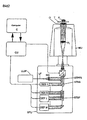
- Figure 1 shows a first advantageous arrangement.
- a microscope unit MU (in this case an inverted microscope for observing a sample P located on a table T that can be adjusted in the x, y and z directions via an objective O and a tube lens TL) is used to illuminate light with the aid of a scanning unit SU from a laser light source LLS with one or more wavelengths directly or through an optical fiber LF via a collimating optics KO and a primary beam splitter STPS focused in a sample.
- the Scannner S allows the deflection of the light beam in the x- and y-direction, the detection of unler Kunststoffaji sample layers can be done by the vertical adjustment of the sample table T or the objective O.
- the light coming from the sample again passes through the scanner S and is assigned to the detection channels DES1 ...
- a beam switching unit BS for example, a full-wave or partially transmissive mirror
- light LLF from a laser light source having one or more wavelengths is focused into the sample by means of an FCS unit FU via a primary beam splitter STPF.
- the light sources LLS and LLF may also be identical and coupled via suitable deflection and switching elements in the units SU and FU.
- the fluorescent light coming from the sample is passed through secondary beam splitters STSF 1... N into one or more FCS detection channels DEF 1... N and converted into electrical signals for evaluation and transmitted to the control unit CU.
- the signals are used for FCS analysis.
- these can be auto or cross correlation analyzes.
- diffusion times, particle numbers, lifetimes, proportions of components are determined at the current sample location.
- the data acquisition is controlled for both detection units by the same control unit CU and a computer C with a suitable program.
- the control of the sample table T, the vertical lens adjustment of the lens O and the beam switching unit BS is performed by this computer-controlled control unit.
- the recorded FCS image can be linked, for example as an additional color, with channel-wise differently colored LSM images by memory-related assignment.
- FCS / LSM difference or quotient images It is also possible to form and display FCS / LSM difference or quotient images or other combinations.
- the modification of the laser scanning microscope according to the invention and the operative connection with the FCS device unit is effected by suitable programs in the computer by means of a device control unit common to all components.
- Scan unit, FCS unit, microscope unit and sample position system are mechanically, optically and electronically matched and coupled.
- pixels can be marked and placed in the measuring position for the FCS unit and measured.
- the selection of the points of interest may be done automatically according to predetermined criteria (e.g., halftone, texture detection of the image) or by the user after individual evaluation of the image taken with the scanning unit.
- predetermined criteria e.g., halftone, texture detection of the image
- the proposed construction makes it possible to select microscopically small measuring sites in the sample to be investigated using the FCS method.
- Figure 2 shows a further advantageous arrangement.
- a common laser unit LLSF and a common primary beam splitter STPFS are provided on / in a common unit SFU.
- the detectors DEF and DES can be identical.
- the measuring and evaluation mode can be selected by means of the control unit CU.
- the advantageous arrangement results from the common localization of the LSM and the FCS detection channels in one unit. Similar to the structure described in FIG. 1, laser light of one or more wavelengths is focused into the sample by means of collimating optics and the primary beam splitter by a scanning unit.
- a particular advantage of this construction is that the measuring location for the FCS measurement can also be selected with the aid of the scanners.
- this makes it possible to advantageously extend the FCS analysis method to an imaging method (Scanning FCM: S-FCSM). Reflected light and fluorescent light is captured by the lens, in turn traverses the scanners and is redirected by one or more secondary beams into one or more LSM detection channels or FCS detection channels. In this case, a separation according to spectral properties or polarization properties can take place.
- the detected light induces electrical signals which are routed to the control unit with a computer connected to a suitable program and used there for FCS analysis or for image reconstruction.
- the laser scanning microscope is here modified so that it contains components and evaluation methods that allow to perform FCS measurements. Scanning components and FCS components are combined in accordance with the invention in such a way that a jet discharge or jet switching, as shown in FIG. 1, can be dispensed with.
- the advantage of this arrangement is that no sample movements are required to perform the FCS analyzes at the previously selected points, since the measuring location can be adjusted by means of the scanners and by vertical adjustment of the objective.
- the operative connection of the operating modes takes place either by the scanner being stopped directly during the scanning process and by an FCS evaluation being tracked at the sample points set thereby or after the scanning process Adjusting the mirrors or adjusting the table while the scanner is stationary will cause an FCS evaluation at certain points
- S-FCM scanning fluorescence correlation microscope
Landscapes
- Physics & Mathematics (AREA)
- Chemical & Material Sciences (AREA)
- Analytical Chemistry (AREA)
- General Physics & Mathematics (AREA)
- Optics & Photonics (AREA)
- Health & Medical Sciences (AREA)
- Computer Vision & Pattern Recognition (AREA)
- General Engineering & Computer Science (AREA)
- Engineering & Computer Science (AREA)
- Nuclear Medicine, Radiotherapy & Molecular Imaging (AREA)
- Life Sciences & Earth Sciences (AREA)
- Biochemistry (AREA)
- General Health & Medical Sciences (AREA)
- Immunology (AREA)
- Pathology (AREA)
- Investigating, Analyzing Materials By Fluorescence Or Luminescence (AREA)
- Microscoopes, Condenser (AREA)
Abstract
Description
- Die Fluoreszenz-Korrelations-Spektroskopie (FCS) mit ihrer Realisierung in einem Mikroskopaufbau (FCM) bewährt sich insbesondere dort zur Untersuchung biomolekularer Wechselwirkungen, wo die Untersuchungen in sehr geringen Konzentrationsbereichen kleiner 1µMol und in Meßvolumina kleiner 10-14 I stattfinden1. Solange die zu untersuchenden Proben homogen sind, spielt der Meßort nur eine untergeordnete Rolle. Im Falle von strukturierten Proben wie zum Beispiel biologischen Zellen, ist die Kenntnis bzw, die Auswahl des Meßortes aber von entscheidender Bedeutung. Diese Kenntnis über den MeßOrt wurde bisher über klassische Durchlicht-bzw. Auflicht-Mikroskopie gewonnen. Dazu wurde z.B. zwischen der FCS-Detektionseinheit und einer klassischen Fluoreszenzmikroskopanordnung umgeschaltet. Die Anwendung der klassischen Mikroskopie hat mehrere Nachteile. Einerseits werden dabei die Proben einer hohen Strahlungsbelastung ausgesetzt, andererseits kann der optimale Meßort im dreidimensionalen Koordinatensystem nicht mit der erforderlichen Präzision von weniger 1 µm lokalisiert werden.
- WO 9416313 beschreibt ein "Laser-Korrelations-Mikroskop" mit Einzellaser und Einzeldelektor, wobei über eine Tischsteuerung unterschiedliche Probenpukte einzeln angesteuert werden.
- US5079169 beschreibt eine Synchronisterung einer videokamera mit Laserpulsen zur Durchführung von Fluoreszenz-Lebensdauermessungen
- In Petersen et al: "Quantitation of membrane receptor distributions...."(Biophysical Journal, Sept. 1993, USA, Bd.65,Nr. 3,S.1135-1146) wird eine Korrelation von mittels eines LSM erzeugten Fluoreszenzbildem zueinander zur Rauschunteredrückung beschrieben.
- Wiseman et al " Dynamic image correlation spectroscopy..."SPIE Proceedings ISSN0277-786X, San Jose CA 23.-24.Jan2000 beschreiben die Korrelationsspektroskopie und die Kreuzkorrelationsspetroskopie.
- Hong Qian et al "Analysis of Confocal Laser-Microscpe...", Applied Optics Bd, 30, Nr. 10, April 1991, S.1 185-1195 beschreiben in gesonderten Abschnitten konfokale Scanningmikroskope und FCS Messungen.
- Diaspro et al" Three-dimensional fluorescence microscopy..."Proceedings of the first joint BMES 1999, vol.2, XP001005601 beschreiben ein LSM mit Zweiphotonenanregung.
- Die in den Patentansprüchen sowie anhand der bildlichen Darstellungen unten beschriebenen Verfahren ermöglichen vorteilhaft die Erweiterung der FCS Methode zu einem bildgebenden Verfahren (S-FCM). Damit können Aussagen zur räumlichen Verteilung der zu untersuchenden molekularen Wechselwirkungen gewonnen werden.
- In Bild 1 ist eine erste vorteilhafte Anordnung dargestellt.
- Mit einer Mikroskopeinheit MU (hier ein inverses Mikroskop zur Beobachtung einer auf einem in x-, y- und z-Richtung verstellbaren Tisch T befindlichen Probe P über ein unterhalb der Probe angeordnetes Objektiv O und eine Tubuslinse TL) wird mit Hilfe einer Scaneinheit SU Licht aus einer Laserlichtquelle LLS mit einer oder mehreren Wellenlängen direkt oder durch eine Lichtleitfaser LF über eine Kollimationsoptik KO sowie einem primären Strahlteiler STPS in eine Probe fokusiert. Der Scannner S erlaubt das Ablenken des Lichtstrahles in x- und y-Richtung, die Erfassung unlerschiedlicher Probenschichten kann durch die vertikale Verstellung des Probentisches T oder des Objektives O erfolgen. Das von der Probe kommende Licht durchläuft wieder den Scannner S und wird mittels der sekundären Strahlteiler STSS 1...N den Detektionskanälen DES1...N zugeordnet und in elektrische Signale zur Auswertung über eine Kontrolleinheit CU in einem Computer C umgewandelt. Die gemessenen Signale werden zur Gewinnung von Bildinformationen genutzt. Mit Hilfe einer Strahlumschaltungseinheit BS, beispielsweise eines ein- und ausschwenkbaren Vollspiegels oder teildurchlässigen Spiegels wird Licht LLF aus einer Laserlichtquelle mit einer oder mehreren Wellenlängen mit Hilfe einer FCS-Einheit FU über einen primären Strahlteiler STPF in die Probe fokusiert.
- Die Lichtquellen LLS und LLF können auch identisch sein und über geeignete Umlenk- und Schaltelemente in die Einheiten SU bzw. FU eingekoppelt werden.
- Das von der Probe kommende Fluoreszenzlicht wird durch sekundäre Strahlteiler STSF 1...N in einen oder mehrere FCS-Detektionskanäle DEF 1... N geleitet und zur Auswertung in elektrische Signale umgewandelt und der Kontrolleinheit CU übermittelt. Die Signale werden zur FCS-Analyse verwendet.
- Je nach Anzahl der installierten Detektionskanäle kann es sich um Auto-oder Kreuzkorrelationsanalysen handeln.
- Hierbei werden am aktuellen Probenort beispielsweise Diffusionszeiten, Teilchenzahlen, Lebensdauern, Anteile von Komponenten ermittelt.
- Die Datenaquise wird für beide Detektionseinheiten von der gleichen Kontrolleinheit CU und einem Computer C mit geeignetem Programm gesteuert. Ebenso erfolgt die Steuerung des Probentisches T, der vertikalen Objektiveinstellung des Objektives O und der Strahlumschaltungseinheit BS durch diese computergesteuerte Kontrolleinheit. Durch die integration einer FCS-Detektionseinheit in ein konfokales Laser-Scanning-Microskop-System ergibt sich somit die Möglichkeit, auch FCS-Analyseergebnisse von Messungen an verschiedene Probenorten zu einem bildhaften Ergebnis zu kombinieren. Dadurch ergibt sich eine vorteilhafte Anordnung, die geeignet ist, FCS-Meßorte probenschonend mit hoher Genauigkeit festzulegen und andererseits auch FCS-Analysenergebnisse von Messungen an verschiedenen Orten zur Bildgebung zu verwenden.
- Beispielsweise ist es vorteilhaft möglich, über unterschiedliche Farbgebung eine farbige flächenhafte oder räumliche Darstellung der Diffusionzeiten oder anderer Analysenergebnisse in Abhängigkeit vom meßort zu erzeugen.
- Weiterhin kann durch speichermäßige Zuordnung das aufgenommene FCS Bild beispielsweise als Zusatzfarbe bildlich mit kanalweise andersfarbigen LSM-Bildem verknüpft werden.
- Es können auch FCS/LSM Differenz- oder Quotientenbilder oder anderweitige Kombinationen gebildet und dargestellt werden.
- Die erfindungsgemäße Modifikation des Laser-Scanning-Mikroskopes und die wirkungsmäßige Verbindung mit der FCS-Geräteeinheit erfolgt durch geeignete Programme im Computer mittels einer für alle Komponenten gemeinsamen Gerätesteuereinheit. Scaneinheit, FCS-Einheit, Mikroskopeinheit und Probenpositionssystem sind mechanisch, optisch und elektronisch aufeinander abgestimmt und verkoppelt.
- Nach dem Scannen der Probe können Bildpunkte markiert und in die Meßposition für die FCS-Einheit gebracht und vermessen werden.
- Die Auswahl der interessierenden Punkte kann automatisch nach vorgegebenen Kriterien (z.B. Raster, Strukturerfassung des Bildes) oder durch den Benutzer nach individueller Bewertung des mit der Scaneinheit aufgenommenen Bildes erfolgen.
- Der vorgeschlagene Aufbau ermöglich die gezielte Auswahl mikroskopisch kleiner Meßorte in der mit der FCS-Methode zu untersuchenden Probe. Außerdem ist es möglich, aus einer systematischen Folge von FCS-Messungen die räumliche Variation der FCS-Analysenergebnisse bildhaft zu erfassen, darzustellen und dem LSM-Bild zuzuordnen.
- In Bild 2 ist eine weitere vorteilhafte Anordnung dargestellt.
- Hier ist an/in einer gemeinsamen Einheit SFU eine gemeinsame Lasereinheit LLSF vorgesehen sowie ein gemeinsamer Primärstrahlteiler STPFS. Dargestellt sind separate Strahlteiter und Detektoren DEF, STSF und DES, STSS für die LSM- und FCS-Detektion. Vorteilhaft können die Detektoren DEF und DES baugleich sein. Der Meß- und Auswertemodus kann mittels der Kontrolleinheit CU gewählt werden.
- Die vorteilhafte Anordnung ergibt sich durch die gemeinsame Lokalisation der LSM- und der FCS-Detektionskanälen in einer Einheit. Ähnlich dem Aufbau, der in Bild 1 beschrieben wurde, wird Laserlicht einer oder mehrerer Wellenlängen mit Hilfe einer Kollimationsoptik und des primären Srahlteilers durch eine Scaneinheit in die Probe fokusiert. Ein besonderer Vorteil dieses Aufbaus ist, daß auch der Meßort für die FCS-Messung mit Hilfe der Scanner gewählt werden kann. Insbesondere ist es dadurch möglich, die FCS-Analysenmethode zu einem bildgebenden Verfahren (Scanning FCM: S-FCSM) vorteilhaft zu erweitern. Reflektiertes Licht und Fluoreszenzlicht wird vom Objektiv aufgefangen, durchläuft wiederum die Scanner und wird von einem oder mehreren sekundären Strahlteilem in einen oder mehrere LSM-Detektionskanäle oder FCS-Detektionskanäle umgeleitet. Dabei kann eine Trennung nach spektralen Eigenschaften oder Polarisationseigenschaften erfolgen. Das detektierte Licht induziert elektrische Signale die zur Kontrolleinheit mit angeschlossenem Computer nebst geeignetem Programm geleitet und dort zur FCS-Analyse bzw. zur Bild-rekonstruktion verwendet werden.
- Das Laser-Scanning-Mikroskop ist hier so modifiziert, daß es Komponenten und Auswerteverfahren enthält, die es erlauben, auch FCS-Messungen durchzuführen. Scankomponenten und FCS-Komponenten sind erfindungsgemäß so kombiniert, daß eine Strahlteitung bzw. Strahlumschaltung, wie sie im Bild 1 dargestellt wurde, entfallen kann. Der Vorteil dieser Anordnung besteht darin, daß zur Durchführung der FCS-Analysen an den vorher ausgewählten Punkten keine Probenbewegungen mehr erforderlich sind, da der Meßort mit Hilfe der Scanner und durch vertikale Verstellung des Objektivs eingesteilt werden kann.
- Die wirkungsmäßige Verbindung der Betriebsmodi erfolgt, indem entweder direkt während des Scanvorganges der Scanner angehalten wird und an dem hierdurch eingestellten Probenpunkte eine FCS-Auswertung verfolgt oder nach dem Scanvorgang durch Einstellen der Spiegel oder Verstellen des Tisches bei stehenden Scannerspiegein an bestimmten Punkten eine FCS Auswertung erfolgt
- Durch die Anordnung gemaß Bild 2 sind FCS-Messungen mit hoher Positioniergenauigkeit in kürzerer Folge möglich. Dieser vorgeschlagene Aufbau stellt ein scannendes Fluoreszenz-Korrelations-Mikroskop (S-FCM) dar, welches erfindungsgemäß sowohl strukturelle als auch biochemische Informationen bildhaft darstellen kann.
Claims (6)
- Verfahren zur Detektion von Fluoreszenzlicht mit wenigstens einer bildgebenden Mikroskopeinheit beruhend auf dem Prinzip der Laser- Scanning -Mikroskopie und wenigstens einer Gerätekomponente zur Analyse molekularer Wechselwirkungen in kleinen Volumina mittels der Fluoreszenz- Korrelations-Spektroskopie, gekennzeichnet dadurch, daß
Meßorte für die Analyse molekularer Wechselwirkung mit Hilfe des bildgebenden Verfahrens mindestens zweidimensional bestimmt und ausgewählt werden
sowohl die bildgebende Mikroskopeinheit als auch die Gerätekomponente mit einer gemeinsamen Steuereinheit betrieben werden,
die Analysenergebnisse dem Bild der bildgebenden Mikroskopeinheit zugeordnet
und über die Steuereinheit und einen Computer mindestens die Analysenergebnisse der Gerätekomponente bildhaft dargestellt werden,
wobei die Probe punktweise mindestens zweidimensional mit Beleuchtungslicht abgescannt und das von der Probe kommende Licht über mindestens einen ersten
und während des Scanvorganges und / oder nach dem Scanvorgang für mindestens einen Probenpunkt eine FCS - Auswertung erfolgt - Verfahren nach Anspruch 1, wobei die Auswahl des Probenortes für die FCS-Messung mit Hilfe eines verfahrbaren Probentisches und/oder vertikaler Verstellung des Objektives manuel und/ oder automatisch erfolgt
- Verfahren nach einem der Ansprüche 1-2, wobei die Auswahl des Probenortes für die FCS-Messung manuel und/ oder automatisch mit Hilfe von mindestens einem Scanner erfolgt.
- Verfahren nach Anspruch 1 , wobei für mindestens einen Probenpunkt eine Abspeicherung und speichermäßige Zuordnung sowohl des beim Scannen detektierten Wertes als auch mindestens eines bei der FCS-Auswertung detektierten Wertes erfolgt.
- Verfahren nach Anspruch 1 oder 4 wobei die obenstehenden Verfahrensschritte für mehrere automatisch und/ oder manuell vorgewählte Probenpunkte erfolgen.
- Verfahren nach einem der Ansprüche 1,4 oder 5, dadurch gekennzeichnet, daß entweder direkt während des Scanvorganges der Scanner angehalten wird und an dem hierdurch eingestellten Probenpunkt eine FCS- Auswertung erfolgt oder nach dem Scanvorgang durch Einstellen der Spiegel oder Verstellen des Tisches bei stehenden Scannerspiegeln eine FCS Auswertung erfolgt .
Applications Claiming Priority (3)
| Application Number | Priority Date | Filing Date | Title |
|---|---|---|---|
| DE10008594 | 2000-02-22 | ||
| DE10008594.6A DE10008594B4 (de) | 2000-02-22 | 2000-02-22 | Einrichtung und Verfahren zur ortsaufgelösten Fluoreszenz-Korrelations-Spektroskopie |
| PCT/EP2001/001663 WO2001063259A1 (de) | 2000-02-22 | 2001-02-15 | Verfahren und anordnung zur detektion des von einer probe kommenden lichtes |
Publications (2)
| Publication Number | Publication Date |
|---|---|
| EP1183525A1 EP1183525A1 (de) | 2002-03-06 |
| EP1183525B1 true EP1183525B1 (de) | 2006-09-20 |
Family
ID=7632205
Family Applications (1)
| Application Number | Title | Priority Date | Filing Date |
|---|---|---|---|
| EP01919284A Revoked EP1183525B1 (de) | 2000-02-22 | 2001-02-15 | Verfahren zur detektion des von einer probe kommenden lichtes |
Country Status (6)
| Country | Link |
|---|---|
| US (1) | US7456026B2 (de) |
| EP (1) | EP1183525B1 (de) |
| JP (1) | JP2003524180A (de) |
| DE (2) | DE10008594B4 (de) |
| HK (1) | HK1046167B (de) |
| WO (1) | WO2001063259A1 (de) |
Families Citing this family (15)
| Publication number | Priority date | Publication date | Assignee | Title |
|---|---|---|---|---|
| DE10222359B4 (de) * | 2002-05-21 | 2005-01-05 | Max Planck-Gesellschaft zur Förderung der Wissenschaften e.V. | Verfahren zur spektral differenzierenden, bildgebenden Messung von Fluoreszenzlicht |
| CN1662810A (zh) * | 2002-06-21 | 2005-08-31 | 奥林巴斯株式会社 | 生物分子分析装置 |
| JP2004347562A (ja) * | 2003-05-26 | 2004-12-09 | Olympus Corp | 測定装置 |
| JP2004361086A (ja) * | 2003-05-30 | 2004-12-24 | Olympus Corp | 生体分子解析装置 |
| DE10327531B4 (de) * | 2003-06-17 | 2006-11-30 | Leica Microsystems Cms Gmbh | Verfahren zur Messung von Fluoreszenzkorrelationen in Gegenwart von langsamen Signalschwankungen |
| DE10327987A1 (de) * | 2003-06-21 | 2005-01-20 | MAX-PLANCK-Gesellschaft zur Förderung der Wissenschaften e.V. | Konfokales optisches System |
| EP1760454A4 (de) | 2004-06-24 | 2008-09-03 | Olympus Corp | Photometrische fluoreszenzvorrichtung |
| DE102004034961A1 (de) * | 2004-07-16 | 2006-02-02 | Carl Zeiss Jena Gmbh | Lichtrastermikroskop mit linienförmiger Abtastung und Verwendung |
| DE102004034987A1 (de) * | 2004-07-16 | 2006-02-02 | Carl Zeiss Jena Gmbh | Lichtrastermikroskop und Verwendung |
| JP4425098B2 (ja) * | 2004-09-06 | 2010-03-03 | 浜松ホトニクス株式会社 | 蛍光顕微鏡および蛍光相関分光解析装置 |
| WO2006049180A1 (ja) * | 2004-11-01 | 2006-05-11 | Olympus Corporation | 発光測定装置及び発光測定方法 |
| WO2006087727A1 (en) * | 2005-02-15 | 2006-08-24 | Tata Institute Of Fundamental Research | Fluorescence correlation microscopy with real-time alignment readout |
| DE102005009188A1 (de) * | 2005-03-01 | 2006-09-07 | Carl Zeiss Jena Gmbh | Punktscannendes Laser-Scanning-Mikroskop sowie Verfahren zur Einstellung eines Mikroskopes |
| DE102006034905B4 (de) * | 2006-07-28 | 2015-07-30 | Carl Zeiss Microscopy Gmbh | Anordnung zur Signalverarbeitung am Ausgang eines Mehrkanaldetektors |
| JPWO2009104719A1 (ja) * | 2008-02-22 | 2011-06-23 | 株式会社ニコン | レーザ走査顕微鏡 |
Family Cites Families (7)
| Publication number | Priority date | Publication date | Assignee | Title |
|---|---|---|---|---|
| US5079169A (en) * | 1990-05-22 | 1992-01-07 | The Regents Of The Stanford Leland Junior University | Method for optically manipulating polymer filaments |
| EP0679251B1 (de) | 1993-01-18 | 1998-04-08 | Evotec BioSystems GmbH | Verfahren und vorrichtung zur bewertung der fitness von biopolymeren |
| DE19533092A1 (de) * | 1995-09-07 | 1997-03-13 | Basf Ag | Vorrichtung zur parallelisierten Zweiphotonen-Fluoreszenz-Korrelations-Spektroskopie (TPA-FCS) und deren Verwendung zum Wirkstoff-Screening |
| DE19702914C2 (de) * | 1997-01-28 | 1998-12-24 | Max Planck Gesellschaft | Verfahren und Anordnung zum Bestimmen vorgegebener Eigenschaften von Zielpartikeln eines Probenmediums |
| DE19649605A1 (de) * | 1996-11-29 | 1998-06-04 | Deutsches Krebsforsch | Fluoreszenzkorrelationsspektroskopiemodul für ein Mikroskop |
| DE19757740C2 (de) * | 1997-12-23 | 2000-04-13 | Evotec Biosystems Ag | Verfahren zum Nachweis von Assoziations-, Dissoziations-, Verknüpfungs- oder Spaltreaktionen sowie Konformationsänderungen mittels Koinzidenzanalyse |
| DE19840489A1 (de) * | 1998-09-04 | 2000-03-09 | Basf Ag | Wirkstoffzubereitungen sowie ein Verfahren zu deren Herstellung |
-
2000
- 2000-02-22 DE DE10008594.6A patent/DE10008594B4/de not_active Expired - Fee Related
-
2001
- 2001-02-15 JP JP2001562176A patent/JP2003524180A/ja active Pending
- 2001-02-15 DE DE50111035T patent/DE50111035D1/de not_active Expired - Lifetime
- 2001-02-15 EP EP01919284A patent/EP1183525B1/de not_active Revoked
- 2001-02-15 HK HK02106587.4A patent/HK1046167B/zh not_active IP Right Cessation
- 2001-02-15 US US10/009,287 patent/US7456026B2/en not_active Expired - Lifetime
- 2001-02-15 WO PCT/EP2001/001663 patent/WO2001063259A1/de not_active Ceased
Also Published As
| Publication number | Publication date |
|---|---|
| US7456026B2 (en) | 2008-11-25 |
| HK1046167A1 (en) | 2002-12-27 |
| HK1046167B (zh) | 2007-07-06 |
| US20050271549A1 (en) | 2005-12-08 |
| DE10008594B4 (de) | 2018-09-20 |
| DE10008594A1 (de) | 2001-08-23 |
| EP1183525A1 (de) | 2002-03-06 |
| WO2001063259A1 (de) | 2001-08-30 |
| JP2003524180A (ja) | 2003-08-12 |
| DE50111035D1 (de) | 2006-11-02 |
Similar Documents
| Publication | Publication Date | Title |
|---|---|---|
| EP1248132B1 (de) | Verfahren und Anordnung zur tiefenaufgelösten optischen Erfassung einer Probe | |
| EP2350726B1 (de) | Kombinationsmikroskopie | |
| EP3899629B1 (de) | Verfahren und vorrichtung zum punktförmigen beleuchten einer probe in einem mikroskop | |
| DE69806496T2 (de) | Gerät und verfahren zur mikroskopie unter verwendung räumlich modulierten lichtes | |
| EP0977069B2 (de) | Verfahren und Anordnung zur konfokalen Mikroskopie | |
| EP1307774B1 (de) | Anordnung zur erhöhung der tiefendiskriminierung optisch abbildender systeme | |
| DE10008594B4 (de) | Einrichtung und Verfahren zur ortsaufgelösten Fluoreszenz-Korrelations-Spektroskopie | |
| DE10038526B4 (de) | Verfahren und Anordnung zur Erfassung des wellenlängenabhängigen Verhaltens einer beleuchteten Probe | |
| EP2807515B1 (de) | Mikroskop und verfahren für die hochauflösende 3-d fluoreszenzmikroskopie | |
| WO2008125605A2 (de) | Verfahren und anordnung zur optischen abbildung mit tiefendiskriminierung | |
| DE10151216A1 (de) | Verfahren zur optischen Erfassung von charakteristischen Größen einer beleuchteten Probe | |
| EP2825908A1 (de) | Hochauflösende scanning-mikroskopie | |
| DE102011086018A1 (de) | Verfahren und Anordnung zur Autofokussierung eines Mikroskops | |
| DE10063276A1 (de) | Scanmikroskop | |
| EP4359770B1 (de) | Verfahren und vorrichtung zur erfassung von helligkeitsinformationen einer probe | |
| DE10155002A1 (de) | Verfahren und Anordnung zur tiefenaufgelösten optischen Erfassung einer Probe | |
| DE10118463A1 (de) | Verfahren und Anordnung zur tiefenaufgelösten optischen Erfassung einer Probe | |
| EP0805996A1 (de) | Verfahren und vorrichtung zum aufnehmen eines objektes | |
| EP3992688A1 (de) | Vorrichtung und verfahren zur erfassung von bilddaten | |
| WO2011018181A1 (de) | Mikroskop zur messung von totalreflexions-fluoreszenz | |
| DE10317669B4 (de) | Verfahren zur Separierung von Detektionskanälen eines mikroskopischen Systems | |
| WO2006003178A1 (de) | Rastermikroskop und verfahren zur untersuchung von biologischen proben mit einem rastermikroskop | |
| EP1209504B1 (de) | Verfahren und eine Anordnung zur Abtastung mikroskopischer Objekte mit einer Scaneinrichtung | |
| DE102017105719A1 (de) | Multi-Pinhole-Lichtrastermikroskop und -mikroskopieverfahren | |
| DE10329756B4 (de) | Rastermikroskop mit einer Vorrichtung zur Fluoreszenz-Korrelations-Spektroskopie |
Legal Events
| Date | Code | Title | Description |
|---|---|---|---|
| PUAI | Public reference made under article 153(3) epc to a published international application that has entered the european phase |
Free format text: ORIGINAL CODE: 0009012 |
|
| 17P | Request for examination filed |
Effective date: 20011002 |
|
| AK | Designated contracting states |
Kind code of ref document: A1 Designated state(s): AT BE CH CY DE DK ES FI FR GB GR IE IT LI LU MC NL PT SE TR |
|
| 17Q | First examination report despatched |
Effective date: 20040317 |
|
| RBV | Designated contracting states (corrected) |
Designated state(s): CH DE FR GB LI SE |
|
| GRAP | Despatch of communication of intention to grant a patent |
Free format text: ORIGINAL CODE: EPIDOSNIGR1 |
|
| RTI1 | Title (correction) |
Free format text: METHOD FOR DETECTING THE LIGHT COMING FROM A SAMPLE |
|
| GRAS | Grant fee paid |
Free format text: ORIGINAL CODE: EPIDOSNIGR3 |
|
| GRAA | (expected) grant |
Free format text: ORIGINAL CODE: 0009210 |
|
| AK | Designated contracting states |
Kind code of ref document: B1 Designated state(s): CH DE FR GB LI SE |
|
| REG | Reference to a national code |
Ref country code: GB Ref legal event code: FG4D Free format text: NOT ENGLISH |
|
| REG | Reference to a national code |
Ref country code: CH Ref legal event code: EP |
|
| REG | Reference to a national code |
Ref country code: CH Ref legal event code: NV Representative=s name: BOVARD AG PATENTANWAELTE |
|
| GBT | Gb: translation of ep patent filed (gb section 77(6)(a)/1977) |
Effective date: 20061010 |
|
| REF | Corresponds to: |
Ref document number: 50111035 Country of ref document: DE Date of ref document: 20061102 Kind code of ref document: P |
|
| PG25 | Lapsed in a contracting state [announced via postgrant information from national office to epo] |
Ref country code: SE Free format text: LAPSE BECAUSE OF FAILURE TO SUBMIT A TRANSLATION OF THE DESCRIPTION OR TO PAY THE FEE WITHIN THE PRESCRIBED TIME-LIMIT Effective date: 20061220 |
|
| ET | Fr: translation filed | ||
| REG | Reference to a national code |
Ref country code: HK Ref legal event code: GR Ref document number: 1046167 Country of ref document: HK |
|
| PLBI | Opposition filed |
Free format text: ORIGINAL CODE: 0009260 |
|
| PLAX | Notice of opposition and request to file observation + time limit sent |
Free format text: ORIGINAL CODE: EPIDOSNOBS2 |
|
| 26 | Opposition filed |
Opponent name: LEICA MICROSYSTEMS GMBH LEICA MICROSYSTEMS CMS GMB Effective date: 20070615 |
|
| PLAF | Information modified related to communication of a notice of opposition and request to file observations + time limit |
Free format text: ORIGINAL CODE: EPIDOSCOBS2 |
|
| PLAF | Information modified related to communication of a notice of opposition and request to file observations + time limit |
Free format text: ORIGINAL CODE: EPIDOSCOBS2 |
|
| PLBB | Reply of patent proprietor to notice(s) of opposition received |
Free format text: ORIGINAL CODE: EPIDOSNOBS3 |
|
| RDAF | Communication despatched that patent is revoked |
Free format text: ORIGINAL CODE: EPIDOSNREV1 |
|
| APBM | Appeal reference recorded |
Free format text: ORIGINAL CODE: EPIDOSNREFNO |
|
| APBP | Date of receipt of notice of appeal recorded |
Free format text: ORIGINAL CODE: EPIDOSNNOA2O |
|
| APAH | Appeal reference modified |
Free format text: ORIGINAL CODE: EPIDOSCREFNO |
|
| APBQ | Date of receipt of statement of grounds of appeal recorded |
Free format text: ORIGINAL CODE: EPIDOSNNOA3O |
|
| PLAB | Opposition data, opponent's data or that of the opponent's representative modified |
Free format text: ORIGINAL CODE: 0009299OPPO |
|
| R26 | Opposition filed (corrected) |
Opponent name: LEICA MICROSYSTEMS GMBH LEICA MICROSYSTEMS CMS GMB Effective date: 20070615 |
|
| REG | Reference to a national code |
Ref country code: CH Ref legal event code: PFA Owner name: CARL ZEISS JENA GMBH Free format text: CARL ZEISS JENA GMBH#CARL-ZEISS-PROMENADE 10#07745 JENA (DE) -TRANSFER TO- CARL ZEISS JENA GMBH#CARL-ZEISS-PROMENADE 10#07745 JENA (DE) |
|
| PGFP | Annual fee paid to national office [announced via postgrant information from national office to epo] |
Ref country code: FR Payment date: 20110302 Year of fee payment: 11 Ref country code: DE Payment date: 20110218 Year of fee payment: 11 Ref country code: CH Payment date: 20110222 Year of fee payment: 11 |
|
| PGFP | Annual fee paid to national office [announced via postgrant information from national office to epo] |
Ref country code: GB Payment date: 20110217 Year of fee payment: 11 |
|
| REG | Reference to a national code |
Ref country code: DE Ref legal event code: R064 Ref document number: 50111035 Country of ref document: DE Ref country code: DE Ref legal event code: R103 Ref document number: 50111035 Country of ref document: DE |
|
| APBU | Appeal procedure closed |
Free format text: ORIGINAL CODE: EPIDOSNNOA9O |
|
| PLAB | Opposition data, opponent's data or that of the opponent's representative modified |
Free format text: ORIGINAL CODE: 0009299OPPO |
|
| R26 | Opposition filed (corrected) |
Opponent name: LEICA MICROSYSTEMS GMBH Effective date: 20070615 |
|
| RDAG | Patent revoked |
Free format text: ORIGINAL CODE: 0009271 |
|
| STAA | Information on the status of an ep patent application or granted ep patent |
Free format text: STATUS: PATENT REVOKED |
|
| REG | Reference to a national code |
Ref country code: CH Ref legal event code: PL |
|
| 27W | Patent revoked |
Effective date: 20110908 |
|
| GBPR | Gb: patent revoked under art. 102 of the ep convention designating the uk as contracting state |
Effective date: 20110908 |
|
| REG | Reference to a national code |
Ref country code: DE Ref legal event code: R107 Ref document number: 50111035 Country of ref document: DE Effective date: 20120412 |
|
| PG25 | Lapsed in a contracting state [announced via postgrant information from national office to epo] |
Ref country code: LI Free format text: LAPSE BECAUSE OF THE APPLICANT RENOUNCES Effective date: 20060920 Ref country code: CH Free format text: LAPSE BECAUSE OF THE APPLICANT RENOUNCES Effective date: 20060920 |