EP1181994A1 - Vorrichtung zur Herstellung ringförming gewellter Metallrohre - Google Patents
Vorrichtung zur Herstellung ringförming gewellter Metallrohre Download PDFInfo
- Publication number
- EP1181994A1 EP1181994A1 EP00402299A EP00402299A EP1181994A1 EP 1181994 A1 EP1181994 A1 EP 1181994A1 EP 00402299 A EP00402299 A EP 00402299A EP 00402299 A EP00402299 A EP 00402299A EP 1181994 A1 EP1181994 A1 EP 1181994A1
- Authority
- EP
- European Patent Office
- Prior art keywords
- teeth
- tube
- pressure roller
- smooth tube
- smooth
- Prior art date
- Legal status (The legal status is an assumption and is not a legal conclusion. Google has not performed a legal analysis and makes no representation as to the accuracy of the status listed.)
- Granted
Links
Images


Classifications
-
- B—PERFORMING OPERATIONS; TRANSPORTING
- B21—MECHANICAL METAL-WORKING WITHOUT ESSENTIALLY REMOVING MATERIAL; PUNCHING METAL
- B21D—WORKING OR PROCESSING OF SHEET METAL OR METAL TUBES, RODS OR PROFILES WITHOUT ESSENTIALLY REMOVING MATERIAL; PUNCHING METAL
- B21D15/00—Corrugating tubes
- B21D15/04—Corrugating tubes transversely, e.g. helically
- B21D15/06—Corrugating tubes transversely, e.g. helically annularly
-
- B—PERFORMING OPERATIONS; TRANSPORTING
- B21—MECHANICAL METAL-WORKING WITHOUT ESSENTIALLY REMOVING MATERIAL; PUNCHING METAL
- B21C—MANUFACTURE OF METAL SHEETS, WIRE, RODS, TUBES, PROFILES OR LIKE SEMI-MANUFACTURED PRODUCTS OTHERWISE THAN BY ROLLING; AUXILIARY OPERATIONS USED IN CONNECTION WITH METAL-WORKING WITHOUT ESSENTIALLY REMOVING MATERIAL
- B21C37/00—Manufacture of metal sheets, rods, wire, tubes, profiles or like semi-manufactured products, not otherwise provided for; Manufacture of tubes of special shape
- B21C37/06—Manufacture of metal sheets, rods, wire, tubes, profiles or like semi-manufactured products, not otherwise provided for; Manufacture of tubes of special shape of tubes or metal hoses; Combined procedures for making tubes, e.g. for making multi-wall tubes
- B21C37/15—Making tubes of special shape; Making tube fittings
- B21C37/20—Making helical or similar guides in or on tubes without removing material, e.g. by drawing same over mandrels, by pushing same through dies ; Making tubes with angled walls, ribbed tubes or tubes with decorated walls
- B21C37/205—Making helical or similar guides in or on tubes without removing material, e.g. by drawing same over mandrels, by pushing same through dies ; Making tubes with angled walls, ribbed tubes or tubes with decorated walls with annular guides
Definitions
- the invention relates to a device for producing ring-shaped corrugated metal pipes according to the preamble of claim 1.
- From CH-A-275 509 is a device for producing corrugated pipes with a um the workpiece rotating pressure roller is known, in which the corrugation by teeth the pressure roller (gear) is molded, and the pressure roller by one Longitudinal axis of the tube is rotatably supported and its axis of rotation during the generation of the corrugation even in a perpendicular to the pipe longitudinal axis Plane revolves around the pipe fed to the pressure roller, which in turn passes through its Feed rotates the pressure roller.
- three pressure rollers are preferred, who attack the pipe offset by 120 °.
- the tooth tips on the outer circumference the teeth of the pressure rollers are concavely adapted to the tube diameter formed so that the pressure rollers a self-contained deformation tool form.
- the present invention has for its object to produce metal tubes with an annular corrugation, the ratio of corrugation depth W, to corrugation pitch W s is greater than 0.3.
- the wave depth W t is to be understood as the radial distance between a wave crest and the wave trough.
- the wave pitch W s is the distance between two wave crests. The extremely deep corrugation should be generated without further measures, ie during the corrugation process.
- FIGS. 1 to 7 Exemplary embodiments explained in more detail.
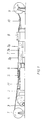
- Figure 1 is a side view of a system for producing a coaxial High-frequency cable shown with a ring-shaped corrugated outer conductor.
- the inner conductor 2 which is insulated with a foam layer, is removed from a supply coil 1 deducted continuously.
- a metal band M preferably a copper band is made of removed from a reel 3 and cleaned in a cleaning system 4.
- the Metal strip M is then in a forming device 5, which does not consist of several designated form steps exists to a surrounding the insulated inner conductor 2 Slotted tube shaped.
- the longitudinal slot is welded in a welding device 6.
- the inside diameter of the welded pipe is slightly larger than the outside diameter of the insulated inner conductor 2, so that the insulating layer is not caused by the welding heat is affected.
- a collet trigger 7 the welded pipe as well the insulated inner conductor 2 is transported through the system in the direction of the arrows.
- the Collet trigger 7 has a plurality of pairs of jaws 7a, which is the welded Grip the pipe in a pincer shape.
- the pairs of jaws 7a are on an endless chain 7b attached, which is driven in a manner not shown by an electric motor.
- the corrugated device 8 is seen behind the collet trigger 7 in the direction of flow arranged in which a corrugated metal tube is produced from the smooth metal tube, whose troughs sit closely on the insulating layer and press it in a little. On in this way a coaxial radio frequency cable is obtained in which the gap between the insulating layer and the outer conductor is sealed.
- the insulated inner conductor 2 provided with the corrugated metal tube is finally opened a cable drum 9 wound up.
- a dancer arrangement 10 regulates the Pulling speed of the cable drum 9.
- a corrugated outer conductor can be used in a manner not shown Plastic outer jacket are extruded.
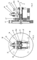
- the corrugated device 8 is described in more detail with reference to FIGS. 2 to 5.
- a guide bushing 12 is fastened in a rotationally drivable manner.
- the inner one Diameter of the guide bush 12 is approximately equal to the outer diameter of the welded smooth tube G.
- the guide bush 12 has a recess 12a, in which engages the pressure roller 13 functioning as a corrugated tool.
- the pressure roller 13 is in a bearing block 14 is freely rotatable.
- the bearing block 14 is by means of a Adjustment spindle 15, which is guided in a threaded bush 16, in the radial direction adjustable.
- the threaded bushing 16 is firmly connected to the shaft head 11 Head plate 17 rotatably mounted. With a counterweight is designated, which for ensures a smooth run of the corrugated device 8.
- the depth of the corrugation to be introduced into the smooth tube G is determined by the Threaded spindle 15 set.
- the Pressure roller 13 When the shaft head 11 is driven in rotation, the Pressure roller 13 the smooth tube G and forms the corrugation. Since the smooth tube G by the collet trigger 7 a feed is given, the pressure roller 13 is so driven that it rotates about its axis of rotation. This causes the last curl to appear generating tooth of the pressure roller 13 from the trough and the subsequent tooth penetrates into the advanced smooth tube G. In this way, with the Pipe longitudinal axis rotating and driven about its own axis of rotation pressure roller 13 continuously produces a tube with an annular corrugation.
- FIGs 4 and 5 is a corrugated device with two opposite one another Pressure rollers 13 shown. In this way, at the same rotational speed of the Wellerkopfes 11 can be achieved twice the production speed.
- FIG. 6 is intended to illustrate the principle of the new corrugation process.
- the pressure roller 13 is with respect to their axis of rotation so approximated the central axis of the smooth tube G that the Immerse teeth Z in the wall of smooth tube G and when rotating the Create pressure roller 13 around the central axis of the smooth tube G an annular corrugation.
- the pressure roller is turned in the direction of the arrow, so that after the completion of a wave valley, the next tooth Z into the smooth tube wall dips.
- the number of teeth Z is limited to 7-11, because only this A ratio of corrugation depth to corrugation slope of more than 0.3 can be achieved.
- the tip diameter of the pressure roller between at 2.3 is up to 3.5 times the shaft pitch or the shaft distance. Too small Tip circle diameter leads to a mechanically unstable pressure roller 13, whereas a too large a tip diameter does not allow the generation of a deep corrugation. Under the diameter of the tooth Z should be the tip circle diameter be understood
- the heads of the teeth Z are flat, as can be seen from FIGS. 3 and 5.
- the width of the teeth Z is more than the diameter of the corrugated tube in the Area of the wave valley. This creates a particularly smooth surface in the area of the Tidal wave reached.
- the fact that the teeth Z are hardened and polished especially in the area of the tooth head. This allows the Reduce wear on both teeth Z and the pipe.
- the flanks of the teeth Z run parallel to one another. This ensures that the Teeth Z do not touch the wave flanks when leaving the trough and thus leave no unwanted impressions.
- the height of the teeth is greater than the corrugation depth. This can be seen particularly in FIG. 7. There the ratio of tooth height Z t to corrugation depth W t is greater than 1.2.
Landscapes
- Engineering & Computer Science (AREA)
- Mechanical Engineering (AREA)
- Manufacturing Of Electric Cables (AREA)
- Shaping Metal By Deep-Drawing, Or The Like (AREA)
- Rigid Pipes And Flexible Pipes (AREA)
- Flexible Shafts (AREA)
- Shaping Of Tube Ends By Bending Or Straightening (AREA)
- Wire Processing (AREA)
- Forging (AREA)
Abstract
Description
Claims (7)
- Vorrichtung zur Herstellung ringförmig gewellter Metallrohre, insbesondere des Außenleiters koaxialer Hochfrequenzkabel, mittels mindestens einer um ein Glattrohr umlaufenden Druckrolle, wobei die Wellen durch Zähne der Druckrolle in das Glattrohr eingeformt werden, die um eine zur Rohrlängsachse rechtwinklige Achse drehbar gelagert ist und deren Drehachse während der Erzeugung der Wellen selbst in einer zur Rohrlängsachse senkrecht stehenden Ebene um das der Druckrolle zugeführte Glattrohr umläuft, welches seinerseits durch seinen Vorschub die Druckrolle dreht, gekennzeichnet durch folgende Merkmale:a) die Zahnköpfe sind eben ausgestaltetb) das Rohr ist vor und hinter dem Eingreifen der Druckrolle (13) eng in einer Führungsbuchse (12) geführt.c) die Anzahl der Zähne (Z) beträgt zwischen 7 und 11, vorzugsweise zwischen 8 und 10.
- Vorrichtung nach Anspruch 1, dadurch gekennzeichnet, daß die Breite (b) der Zähne (Z) gleich oder größer ist als der Durchmesser des Rohres im Wellental ist.
- Vorrichtung nach Anspruch 1 oder 2, dadurch gekennzeichnet, daß die Flanken der Zähne (Z) nahezu parallel zueinander verlaufen.
- Vorrichtung nach einem der Ansprüche 1 bis 3, dadurch gekennzeichnet, daß zwei oder drei Druckrollen (13) gleichmäßig über den Umfang verteilt an dem Glattrohr (G) angreifen.
- Vorrichtung nach einem der Ansprüche 1 bis 4, dadurch gekennzeichnet, daß die Zähne (Z) zumindest im Bereich des Zahnkopfes gehärtet und/oder poliert sind.
- Vorrichtung nach einem der Ansprüche 1 bis 4, dadurch gekennzeichnet daß in die Zahnköpfe Hartmetallteile eingesetzt sind.
- Vorrichtung nach einem der Ansprüche 1 bis 6, dadurch gekennzeichnet, daß der Kopfkreisdurchmesser der Druckrolle (13) bzw. Druckrollen (13) zwischen dem 2,3 bis 3,5fachen der Wellsteigung bzw. dem Wellenabstand liegt.
Priority Applications (11)
| Application Number | Priority Date | Filing Date | Title |
|---|---|---|---|
| EP00402299A EP1181994B1 (de) | 2000-08-17 | 2000-08-17 | Vorrichtung zur Herstellung ringförming gewellter Metallrohre |
| DK00402299T DK1181994T3 (da) | 2000-08-17 | 2000-08-17 | Anordning til fremstilling af ringformede bølgerør |
| DE50003453T DE50003453D1 (de) | 2000-08-17 | 2000-08-17 | Vorrichtung zur Herstellung ringförming gewellter Metallrohre |
| AT00402299T ATE248037T1 (de) | 2000-08-17 | 2000-08-17 | Vorrichtung zur herstellung ringförming gewellter metallrohre |
| ES00402299T ES2200800T3 (es) | 2000-08-17 | 2000-08-17 | Dispositivo para la fabricacion de tubos metalicos con ondulaciones anulares. |
| AU55890/01A AU778357B2 (en) | 2000-08-17 | 2001-07-20 | Device for the manufacture of annular corrugated metal tubes |
| CN01125514.5A CN1222376C (zh) | 2000-08-17 | 2001-08-07 | 用于制造环状波形金属管的装置 |
| CA2355172A CA2355172C (en) | 2000-08-17 | 2001-08-15 | Apparatus for producing annularly corrugated metal tubes |
| BR0103426-0A BR0103426A (pt) | 2000-08-17 | 2001-08-15 | Dispositivo para a produção de tubos de metal, ondulados em forma de anel |
| JP2001247026A JP2002102941A (ja) | 2000-08-17 | 2001-08-16 | 環状波形金属管を製造するための装置 |
| US09/930,309 US6550300B2 (en) | 2000-08-17 | 2001-08-16 | Apparatus for producing annularly corrugated metal tubes |
Applications Claiming Priority (1)
| Application Number | Priority Date | Filing Date | Title |
|---|---|---|---|
| EP00402299A EP1181994B1 (de) | 2000-08-17 | 2000-08-17 | Vorrichtung zur Herstellung ringförming gewellter Metallrohre |
Publications (2)
| Publication Number | Publication Date |
|---|---|
| EP1181994A1 true EP1181994A1 (de) | 2002-02-27 |
| EP1181994B1 EP1181994B1 (de) | 2003-08-27 |
Family
ID=8173816
Family Applications (1)
| Application Number | Title | Priority Date | Filing Date |
|---|---|---|---|
| EP00402299A Expired - Lifetime EP1181994B1 (de) | 2000-08-17 | 2000-08-17 | Vorrichtung zur Herstellung ringförming gewellter Metallrohre |
Country Status (11)
| Country | Link |
|---|---|
| US (1) | US6550300B2 (de) |
| EP (1) | EP1181994B1 (de) |
| JP (1) | JP2002102941A (de) |
| CN (1) | CN1222376C (de) |
| AT (1) | ATE248037T1 (de) |
| AU (1) | AU778357B2 (de) |
| BR (1) | BR0103426A (de) |
| CA (1) | CA2355172C (de) |
| DE (1) | DE50003453D1 (de) |
| DK (1) | DK1181994T3 (de) |
| ES (1) | ES2200800T3 (de) |
Cited By (2)
| Publication number | Priority date | Publication date | Assignee | Title |
|---|---|---|---|---|
| EP2243567A1 (de) * | 2009-04-21 | 2010-10-27 | Nexans | Vorrichtung zur Herstellung von quer zu ihrer Längsrichtung gewellten Rohren |
| CN102248051A (zh) * | 2010-08-02 | 2011-11-23 | 江苏俊知技术有限公司 | 一种波纹管外导体轧制装置 |
Families Citing this family (12)
| Publication number | Priority date | Publication date | Assignee | Title |
|---|---|---|---|---|
| DE10146807A1 (de) * | 2001-09-22 | 2003-04-10 | Nexans | Verfahren zur Herstellung längsnahtgeschweisster schraubenlinienförmig gewellter Metallrohre |
| CA2575279A1 (en) * | 2006-01-30 | 2007-07-30 | Link-Pipe Inc | Apparatus and method for sleeve or sheet corrugation |
| CA2699318C (en) * | 2007-10-01 | 2016-06-28 | Inventio Ag | Deep-drawing device |
| CN101513655B (zh) * | 2008-02-22 | 2011-02-09 | 上海迈信威机电科技有限公司 | 轧纹机的轧纹头的升降装置 |
| US8333099B2 (en) * | 2009-12-21 | 2012-12-18 | Han-Ching Huang | Method for making a tube of a telescopic device |
| CN101961829B (zh) * | 2010-10-10 | 2012-05-16 | 浙江明泰标准件有限公司 | 需要倒角且多槽的螺栓成型工艺 |
| CN102274902B (zh) * | 2011-06-17 | 2013-07-17 | 秦皇岛福格科技有限公司 | 波纹管成型机旋转托盘机构 |
| EP2752256B1 (de) * | 2013-01-07 | 2016-06-15 | Nexans | Vorrichtung zum Wellen eines Rohres |
| CN111438222B (zh) * | 2020-03-19 | 2021-08-20 | 玉环明智科技有限公司 | 一种不连续螺旋管自动成型工装 |
| CN112238172B (zh) * | 2020-09-28 | 2022-12-23 | 广州润球通讯科技有限公司 | 一种用于光缆护套生产的钢带轧纹装置 |
| CN116871375B (zh) * | 2023-09-06 | 2023-11-28 | 杭州万全金属软管有限公司 | 一种不锈钢波纹管加工装置 |
| CN119035994A (zh) * | 2024-09-30 | 2024-11-29 | 海龙(张家港)实业有限公司 | 一种钛合金波纹管的制备方法及成型设备 |
Citations (4)
| Publication number | Priority date | Publication date | Assignee | Title |
|---|---|---|---|---|
| DE458947C (de) * | 1928-04-23 | Friedrich Wempe | Verfahren zur Herstellung von gewellten Rohren fuer Waermeaustauscheinrichtungen | |
| DE2106177A1 (de) * | 1970-05-01 | 1971-11-18 | Northern Electric Co | Rillenprägevorrichtung für Rohre |
| US3780556A (en) * | 1971-09-27 | 1973-12-25 | Andrew Corp | Tube corrugating apparatus and method |
| US6073473A (en) * | 1997-03-12 | 2000-06-13 | Alcatel | Device for corrugating tubes |
Family Cites Families (2)
| Publication number | Priority date | Publication date | Assignee | Title |
|---|---|---|---|---|
| GB1326320A (en) * | 1971-05-10 | 1973-08-08 | Felten & Guilleaume Kabelwerk | Apparatus for corrugating tubes |
| DE4137275A1 (de) * | 1991-11-13 | 1993-05-19 | Kabelmetal Electro Gmbh | Verfahren zur kontinuierlichen herstellung schraubenlinien- oder ringfoermig gewellter metallrohre |
-
2000
- 2000-08-17 EP EP00402299A patent/EP1181994B1/de not_active Expired - Lifetime
- 2000-08-17 ES ES00402299T patent/ES2200800T3/es not_active Expired - Lifetime
- 2000-08-17 DK DK00402299T patent/DK1181994T3/da active
- 2000-08-17 DE DE50003453T patent/DE50003453D1/de not_active Expired - Lifetime
- 2000-08-17 AT AT00402299T patent/ATE248037T1/de active
-
2001
- 2001-07-20 AU AU55890/01A patent/AU778357B2/en not_active Ceased
- 2001-08-07 CN CN01125514.5A patent/CN1222376C/zh not_active Expired - Fee Related
- 2001-08-15 BR BR0103426-0A patent/BR0103426A/pt not_active IP Right Cessation
- 2001-08-15 CA CA2355172A patent/CA2355172C/en not_active Expired - Fee Related
- 2001-08-16 JP JP2001247026A patent/JP2002102941A/ja active Pending
- 2001-08-16 US US09/930,309 patent/US6550300B2/en not_active Expired - Fee Related
Patent Citations (4)
| Publication number | Priority date | Publication date | Assignee | Title |
|---|---|---|---|---|
| DE458947C (de) * | 1928-04-23 | Friedrich Wempe | Verfahren zur Herstellung von gewellten Rohren fuer Waermeaustauscheinrichtungen | |
| DE2106177A1 (de) * | 1970-05-01 | 1971-11-18 | Northern Electric Co | Rillenprägevorrichtung für Rohre |
| US3780556A (en) * | 1971-09-27 | 1973-12-25 | Andrew Corp | Tube corrugating apparatus and method |
| US6073473A (en) * | 1997-03-12 | 2000-06-13 | Alcatel | Device for corrugating tubes |
Cited By (3)
| Publication number | Priority date | Publication date | Assignee | Title |
|---|---|---|---|---|
| EP2243567A1 (de) * | 2009-04-21 | 2010-10-27 | Nexans | Vorrichtung zur Herstellung von quer zu ihrer Längsrichtung gewellten Rohren |
| CN102248051A (zh) * | 2010-08-02 | 2011-11-23 | 江苏俊知技术有限公司 | 一种波纹管外导体轧制装置 |
| CN102248051B (zh) * | 2010-08-02 | 2013-04-03 | 江苏俊知技术有限公司 | 一种波纹管外导体轧制装置 |
Also Published As
| Publication number | Publication date |
|---|---|
| EP1181994B1 (de) | 2003-08-27 |
| JP2002102941A (ja) | 2002-04-09 |
| CN1367052A (zh) | 2002-09-04 |
| AU5589001A (en) | 2002-02-21 |
| BR0103426A (pt) | 2002-03-26 |
| DK1181994T3 (da) | 2003-12-22 |
| US20020029598A1 (en) | 2002-03-14 |
| US6550300B2 (en) | 2003-04-22 |
| AU778357B2 (en) | 2004-12-02 |
| CA2355172A1 (en) | 2002-02-17 |
| ATE248037T1 (de) | 2003-09-15 |
| CN1222376C (zh) | 2005-10-12 |
| DE50003453D1 (de) | 2003-10-02 |
| CA2355172C (en) | 2010-04-27 |
| ES2200800T3 (es) | 2004-03-16 |
Similar Documents
| Publication | Publication Date | Title |
|---|---|---|
| EP1181994B1 (de) | Vorrichtung zur Herstellung ringförming gewellter Metallrohre | |
| DE3715915C2 (de) | ||
| DE68910381T2 (de) | Vorrichtung zum Herstellen von Rohren. | |
| EP1084774B1 (de) | Verfahren zur kontinuierlichen Herstellung längsnahtgeschweisster und gewellter Metallrohre und Vorrichtung zur Durchführung des Verfahrens | |
| DE1900953A1 (de) | Verfahren und Vorrichtung zum Wellen von Kabelmaenteln od.dgl. | |
| DE4137275A1 (de) | Verfahren zur kontinuierlichen herstellung schraubenlinien- oder ringfoermig gewellter metallrohre | |
| EP0288797A1 (de) | Vorrichtung zur Herstellung eines gewickelten Kunstoffrohres | |
| DE1615066C3 (de) | Vorrichtung zum Herstellen eines Hochfrequenz-Koaxialkabels | |
| DE1924483C3 (de) | Vorrichtung zum schraubenlinienförmigen Aufwickeln eines die wandernde Oberfläche eines Wickeldorns bildenden Bandes mit einer der Bandbreite entsprechenden Steigung | |
| EP1262250A2 (de) | Vorrichtung zur kontinuierlichen Herstellung eines schraubenlinienförmig gewellten Metallrohres | |
| DE811945C (de) | Vorrichtung zum Wellen von Rohren | |
| CH649013A5 (de) | Vorrichtung zum wellen von rohren. | |
| DE2400842C2 (de) | Verfahren und Vorrichtung zur Herstellung flexibler Metallrohre | |
| DE2452293C3 (de) | Transportvorrichtung für Rohre | |
| DE4323649A1 (de) | Verfahren zur Herstellung eines schraubenlinien- oder ringförmig gewellten Metallrohres | |
| DE3029447C2 (de) | Vorrichtung zum Wellen von Rohren | |
| DE2721242A1 (de) | Verfahren und vorrichtung zur kontinuierlichen rohrherstellung | |
| DE69509251T2 (de) | Verfahren und vorrichtung zur herstellung von schraubebfoermigen gegenstaenden | |
| DE917723C (de) | Verfahren und Einrichtung zum kontinuierlichen Herstellen von endlosen, nahtlosen, biegsamen Rohren | |
| DE19756579C1 (de) | Werkzeug zum maschinellen Abschneiden eines Kunststoffrohrs sowie ein Verfahren und eine Vorrichtung zum Fertigen von Kunststoffrohrabschnitten | |
| DE3431120C2 (de) | Verfahren und Vorrichtung zum Wellen von Metallrohren | |
| DE60000888T2 (de) | Ein Verfahren und eine Vorrichtung zur kontinuierlichen Herstellung von Förderschnecken für Archimedesförderschnecken | |
| DE2259982A1 (de) | Verfahren und vorrichtung fuer das herstellen von geriffelten rohren | |
| DE2620913C2 (de) | Vorrichtung zum Herstellen schraubenlinienförmig gewellter Rohre | |
| DE1959160A1 (de) | Verfahren und Vorrichtung zum Wellen von Rohren |
Legal Events
| Date | Code | Title | Description |
|---|---|---|---|
| PUAI | Public reference made under article 153(3) epc to a published international application that has entered the european phase |
Free format text: ORIGINAL CODE: 0009012 |
|
| 17P | Request for examination filed |
Effective date: 20010126 |
|
| AK | Designated contracting states |
Kind code of ref document: A1 Designated state(s): AT BE CH CY DE DK ES FI FR GB GR IE IT LI LU MC NL PT SE |
|
| AX | Request for extension of the european patent |
Free format text: AL;LT;LV;MK;RO;SI |
|
| AKX | Designation fees paid |
Free format text: AT BE CH CY DE DK ES FI FR GB GR IE IT LI LU MC NL PT SE |
|
| 17Q | First examination report despatched |
Effective date: 20021210 |
|
| GRAH | Despatch of communication of intention to grant a patent |
Free format text: ORIGINAL CODE: EPIDOS IGRA |
|
| GRAH | Despatch of communication of intention to grant a patent |
Free format text: ORIGINAL CODE: EPIDOS IGRA |
|
| GRAA | (expected) grant |
Free format text: ORIGINAL CODE: 0009210 |
|
| AK | Designated contracting states |
Designated state(s): AT BE CH CY DE DK ES FI FR GB GR IE IT LI LU MC NL PT SE |
|
| PG25 | Lapsed in a contracting state [announced via postgrant information from national office to epo] |
Ref country code: IE Free format text: LAPSE BECAUSE OF FAILURE TO SUBMIT A TRANSLATION OF THE DESCRIPTION OR TO PAY THE FEE WITHIN THE PRESCRIBED TIME-LIMIT Effective date: 20030827 Ref country code: CY Free format text: LAPSE BECAUSE OF FAILURE TO SUBMIT A TRANSLATION OF THE DESCRIPTION OR TO PAY THE FEE WITHIN THE PRESCRIBED TIME-LIMIT Effective date: 20030827 |
|
| REG | Reference to a national code |
Ref country code: GB Ref legal event code: FG4D Free format text: NOT ENGLISH |
|
| REG | Reference to a national code |
Ref country code: CH Ref legal event code: EP |
|
| REG | Reference to a national code |
Ref country code: CH Ref legal event code: NV Representative=s name: CRONIN INTELLECTUAL PROPERTY |
|
| GBT | Gb: translation of ep patent filed (gb section 77(6)(a)/1977) | ||
| REG | Reference to a national code |
Ref country code: IE Ref legal event code: FG4D Free format text: GERMAN |
|
| REF | Corresponds to: |
Ref document number: 50003453 Country of ref document: DE Date of ref document: 20031002 Kind code of ref document: P |
|
| PG25 | Lapsed in a contracting state [announced via postgrant information from national office to epo] |
Ref country code: SE Free format text: LAPSE BECAUSE OF FAILURE TO SUBMIT A TRANSLATION OF THE DESCRIPTION OR TO PAY THE FEE WITHIN THE PRESCRIBED TIME-LIMIT Effective date: 20031127 Ref country code: GR Free format text: LAPSE BECAUSE OF FAILURE TO SUBMIT A TRANSLATION OF THE DESCRIPTION OR TO PAY THE FEE WITHIN THE PRESCRIBED TIME-LIMIT Effective date: 20031127 |
|
| REG | Reference to a national code |
Ref country code: DK Ref legal event code: T3 |
|
| PG25 | Lapsed in a contracting state [announced via postgrant information from national office to epo] |
Ref country code: PT Free format text: LAPSE BECAUSE OF FAILURE TO SUBMIT A TRANSLATION OF THE DESCRIPTION OR TO PAY THE FEE WITHIN THE PRESCRIBED TIME-LIMIT Effective date: 20040127 |
|
| REG | Reference to a national code |
Ref country code: ES Ref legal event code: FG2A Ref document number: 2200800 Country of ref document: ES Kind code of ref document: T3 |
|
| REG | Reference to a national code |
Ref country code: IE Ref legal event code: FD4D |
|
| ET | Fr: translation filed | ||
| PLBE | No opposition filed within time limit |
Free format text: ORIGINAL CODE: 0009261 |
|
| STAA | Information on the status of an ep patent application or granted ep patent |
Free format text: STATUS: NO OPPOSITION FILED WITHIN TIME LIMIT |
|
| 26N | No opposition filed |
Effective date: 20040528 |
|
| PGFP | Annual fee paid to national office [announced via postgrant information from national office to epo] |
Ref country code: MC Payment date: 20050729 Year of fee payment: 6 |
|
| PGFP | Annual fee paid to national office [announced via postgrant information from national office to epo] |
Ref country code: LU Payment date: 20050921 Year of fee payment: 6 |
|
| PG25 | Lapsed in a contracting state [announced via postgrant information from national office to epo] |
Ref country code: MC Free format text: LAPSE BECAUSE OF NON-PAYMENT OF DUE FEES Effective date: 20060831 |
|
| REG | Reference to a national code |
Ref country code: CH Ref legal event code: PCAR Free format text: CRONIN INTELLECTUAL PROPERTY;CHEMIN DE PRECOSSY 31;1260 NYON (CH) |
|
| PG25 | Lapsed in a contracting state [announced via postgrant information from national office to epo] |
Ref country code: LU Free format text: LAPSE BECAUSE OF NON-PAYMENT OF DUE FEES Effective date: 20060817 |
|
| PGFP | Annual fee paid to national office [announced via postgrant information from national office to epo] |
Ref country code: NL Payment date: 20100813 Year of fee payment: 11 Ref country code: ES Payment date: 20100825 Year of fee payment: 11 Ref country code: CH Payment date: 20100824 Year of fee payment: 11 |
|
| PGFP | Annual fee paid to national office [announced via postgrant information from national office to epo] |
Ref country code: FI Payment date: 20100812 Year of fee payment: 11 Ref country code: FR Payment date: 20100901 Year of fee payment: 11 Ref country code: IT Payment date: 20100823 Year of fee payment: 11 Ref country code: AT Payment date: 20100812 Year of fee payment: 11 Ref country code: DE Payment date: 20100823 Year of fee payment: 11 |
|
| PGFP | Annual fee paid to national office [announced via postgrant information from national office to epo] |
Ref country code: GB Payment date: 20100819 Year of fee payment: 11 |
|
| PGFP | Annual fee paid to national office [announced via postgrant information from national office to epo] |
Ref country code: DK Payment date: 20100810 Year of fee payment: 11 |
|
| PGFP | Annual fee paid to national office [announced via postgrant information from national office to epo] |
Ref country code: BE Payment date: 20100810 Year of fee payment: 11 |
|
| BERE | Be: lapsed |
Owner name: *NEXANS Effective date: 20110831 |
|
| REG | Reference to a national code |
Ref country code: NL Ref legal event code: V1 Effective date: 20120301 |
|
| REG | Reference to a national code |
Ref country code: CH Ref legal event code: PL |
|
| GBPC | Gb: european patent ceased through non-payment of renewal fee |
Effective date: 20110817 |
|
| PG25 | Lapsed in a contracting state [announced via postgrant information from national office to epo] |
Ref country code: CH Free format text: LAPSE BECAUSE OF NON-PAYMENT OF DUE FEES Effective date: 20110831 Ref country code: LI Free format text: LAPSE BECAUSE OF NON-PAYMENT OF DUE FEES Effective date: 20110831 |
|
| REG | Reference to a national code |
Ref country code: DK Ref legal event code: EBP |
|
| REG | Reference to a national code |
Ref country code: FR Ref legal event code: ST Effective date: 20120430 |
|
| PG25 | Lapsed in a contracting state [announced via postgrant information from national office to epo] |
Ref country code: IT Free format text: LAPSE BECAUSE OF NON-PAYMENT OF DUE FEES Effective date: 20110817 Ref country code: NL Free format text: LAPSE BECAUSE OF NON-PAYMENT OF DUE FEES Effective date: 20120301 Ref country code: FI Free format text: LAPSE BECAUSE OF NON-PAYMENT OF DUE FEES Effective date: 20110817 Ref country code: BE Free format text: LAPSE BECAUSE OF NON-PAYMENT OF DUE FEES Effective date: 20110831 |
|
| REG | Reference to a national code |
Ref country code: DE Ref legal event code: R119 Ref document number: 50003453 Country of ref document: DE Effective date: 20120301 |
|
| PG25 | Lapsed in a contracting state [announced via postgrant information from national office to epo] |
Ref country code: DK Free format text: LAPSE BECAUSE OF NON-PAYMENT OF DUE FEES Effective date: 20110831 |
|
| PG25 | Lapsed in a contracting state [announced via postgrant information from national office to epo] |
Ref country code: GB Free format text: LAPSE BECAUSE OF NON-PAYMENT OF DUE FEES Effective date: 20110817 Ref country code: FR Free format text: LAPSE BECAUSE OF NON-PAYMENT OF DUE FEES Effective date: 20110831 |
|
| REG | Reference to a national code |
Ref country code: AT Ref legal event code: MM01 Ref document number: 248037 Country of ref document: AT Kind code of ref document: T Effective date: 20110817 |
|
| PG25 | Lapsed in a contracting state [announced via postgrant information from national office to epo] |
Ref country code: AT Free format text: LAPSE BECAUSE OF NON-PAYMENT OF DUE FEES Effective date: 20110817 |
|
| REG | Reference to a national code |
Ref country code: ES Ref legal event code: FD2A Effective date: 20130604 |
|
| PG25 | Lapsed in a contracting state [announced via postgrant information from national office to epo] |
Ref country code: DE Free format text: LAPSE BECAUSE OF NON-PAYMENT OF DUE FEES Effective date: 20120301 |
|
| PG25 | Lapsed in a contracting state [announced via postgrant information from national office to epo] |
Ref country code: ES Free format text: LAPSE BECAUSE OF NON-PAYMENT OF DUE FEES Effective date: 20110818 |