EP1181196B1 - Mehrschichtiger gefrierlagersack - Google Patents
Mehrschichtiger gefrierlagersack Download PDFInfo
- Publication number
- EP1181196B1 EP1181196B1 EP00936470A EP00936470A EP1181196B1 EP 1181196 B1 EP1181196 B1 EP 1181196B1 EP 00936470 A EP00936470 A EP 00936470A EP 00936470 A EP00936470 A EP 00936470A EP 1181196 B1 EP1181196 B1 EP 1181196B1
- Authority
- EP
- European Patent Office
- Prior art keywords
- bag
- inner liner
- thermoplastic film
- layered
- web
- Prior art date
- Legal status (The legal status is an assumption and is not a legal conclusion. Google has not performed a legal analysis and makes no representation as to the accuracy of the status listed.)
- Expired - Lifetime
Links
Images


Classifications
-
- B—PERFORMING OPERATIONS; TRANSPORTING
- B65—CONVEYING; PACKING; STORING; HANDLING THIN OR FILAMENTARY MATERIAL
- B65D—CONTAINERS FOR STORAGE OR TRANSPORT OF ARTICLES OR MATERIALS, e.g. BAGS, BARRELS, BOTTLES, BOXES, CANS, CARTONS, CRATES, DRUMS, JARS, TANKS, HOPPERS, FORWARDING CONTAINERS; ACCESSORIES, CLOSURES, OR FITTINGS THEREFOR; PACKAGING ELEMENTS; PACKAGES
- B65D33/00—Details of, or accessories for, sacks or bags
-
- B—PERFORMING OPERATIONS; TRANSPORTING
- B65—CONVEYING; PACKING; STORING; HANDLING THIN OR FILAMENTARY MATERIAL
- B65D—CONTAINERS FOR STORAGE OR TRANSPORT OF ARTICLES OR MATERIALS, e.g. BAGS, BARRELS, BOTTLES, BOXES, CANS, CARTONS, CRATES, DRUMS, JARS, TANKS, HOPPERS, FORWARDING CONTAINERS; ACCESSORIES, CLOSURES, OR FITTINGS THEREFOR; PACKAGING ELEMENTS; PACKAGES
- B65D31/00—Bags or like containers made of paper and having structural provision for thickness of contents
- B65D31/04—Bags or like containers made of paper and having structural provision for thickness of contents with multiple walls
-
- B—PERFORMING OPERATIONS; TRANSPORTING
- B31—MAKING ARTICLES OF PAPER, CARDBOARD OR MATERIAL WORKED IN A MANNER ANALOGOUS TO PAPER; WORKING PAPER, CARDBOARD OR MATERIAL WORKED IN A MANNER ANALOGOUS TO PAPER
- B31B—MAKING CONTAINERS OF PAPER, CARDBOARD OR MATERIAL WORKED IN A MANNER ANALOGOUS TO PAPER
- B31B2155/00—Flexible containers made from webs
-
- B—PERFORMING OPERATIONS; TRANSPORTING
- B31—MAKING ARTICLES OF PAPER, CARDBOARD OR MATERIAL WORKED IN A MANNER ANALOGOUS TO PAPER; WORKING PAPER, CARDBOARD OR MATERIAL WORKED IN A MANNER ANALOGOUS TO PAPER
- B31B—MAKING CONTAINERS OF PAPER, CARDBOARD OR MATERIAL WORKED IN A MANNER ANALOGOUS TO PAPER
- B31B2170/00—Construction of flexible containers
- B31B2170/20—Construction of flexible containers having multi-layered walls, e.g. laminated or lined
Definitions
- the invention generally concerns the packaging of food, particularly meat.
- the invention was made during attempts to make improved functional "freezer bags" for repackaging and freezer storing uncooked red meat by the ultimate consumer in a manner that reduces so called "freezer burn".
- Other aspects of the invention include methods for preparing the freezer bags and materials and methods for using the bags, for example.
- Reclosable plastic storage bags are relatively old in the art.
- plastic bags are typically available to the public in cartons identified for specific recommended "end use” (such as Storage Bags, Heavy Duty Freezer Bags, Vegetable Bags, Trash Bags).
- end use such as Storage Bags, Heavy Duty Freezer Bags, Vegetable Bags, Trash Bags.
- end use e.g., "ZIPLOC® BRAND Heavy Duty Freezer Bags”.
- freezer bag is hereby defined as a bag having significant functional utility in the storage of food in a freezer.
- Freezer Bags are typically available in the following sizes: 2 gallon; 1 gallon; pleated 1/2 gallon; quart; and pint.
- freezer burn is hereby defined as the name for the dehydration that occurs when unpackaged or improperly packaged food is stored in the low humidity atmosphere of a freezer (see “Packaging Foods With Plastics", by Wilmer A. Jenkins and James P. Harrington, published in 1991 by Technomic Publishing Co., In., at page 305). Consumers typically describe freezer bum in terms of three main visual attributes: ice crystal formation, product dehydration and color change.
- Freezer burn has remained a major complaint among consumers despite the commercial success of thick plastic freezer bags.
- freezer burn can be a reversible process.
- freezer burn causes a complex deterioration of food quality involving undesirable texture changes followed by chemical changes such as degradation of pigments and oxidative rancidity of lipids. Taste, aroma, mouth feel and color can all be ruined.
- Freezer burn of raw red meat is particularly critical because of its impact upon the color of the meat.
- U.S. Patent No. 4,211,091 Campbell
- U.S. Patent No. 4,211,267 Skovgaard
- U.S. Patent No. 4,797,010 discloses a duplex paper bag as a "reheatable, resealable package for fired food”.
- 4,358,466 (assigned to The Dow Chemical Company) relates to an improved "Freezer to Microwave Oven Bag".
- the bag is formed of two wing shaped pouches on each side of an upright spout.
- U.S. Patent No. 5,005,679 (Hjelle) concerns "Tote Bags Equipped With A Cooling Chamber". All of these food bags appear to have very thick food contacting walls compared to the invention described hereinafter. None of these patents appear to focus on freezer bum.
- the present invention provides a multi-layered bag comprising an outer bag and at least one inner liner, the outer bag having two sidewalls including inner and outer surfaces, said sidewalls being attached together along respective lateral edges defining the opening to the multi-layered bag and a folded edge defining the bottom of the multi-layered bag, the inner liner including at least one side wall having a top edge attached to the inner surface of said outer bag, characterized in that the said at least one side wall of the inner liner has at least one free edge.
- the invention also provides a process for making a multi-layered bag having an outer bag and an inner liner, said process comprising steps of: forwarding a first thermoplastic film web having a thickness of greater than 1 mil (25.4 ⁇ ) and a first transverse web width between parallel edges; forwarding at least a second thermoplastic film web having a thickness of less than 2 mil (50.8 ⁇ ) and a second transverse web width between parallel edges, the second transverse web width being smaller than the width of the first thermoplastic film; overlaying the second thermoplastic film web onto the first thermoplastic film web between the parallel edges of the first film web; attaching the second thermoplastic film web to the first thermoplastic film web along parallel edges of the second thermoplastic film web, folding the film webs in the transverse direction; and seal cutting the folded film webs to form a multi-layered bag, characterized in that the second thermoplastic film web is provided as first and second adjacent separate webs, or as a single web in which case there is provided the step of longitudinally perforating or slitting said second thermoplastic film, so
- an apparatus for making multi-layered bags having at least an inner liner bag and an outer support bag comprising: means for forwarding a first thermoplastic film web having a thickness of greater than 1 mil (25.4 ⁇ ) and a first transverse web width between parallel edges; means for forwarding at least a second thermoplastic film web having a thickness of less than 2 mil (50.8 ⁇ ) and a second transverse web width between parallel edges, the second transverse web width being smaller than the width of the first thermoplastic film; means for overlaying the second thermoplastic film web onto the first thermoplastic film web between parallel edges of the first thermoplastic films means for folding the films in the transverse direction; and means for seal cutting the folded films to form bags; characterized in that there is provided either means for longitudinally perforating or slitting said second transverse web or the second thermoplastic film web includes two disconnected adjacent sheets, so as to produce a free edge on at least one side of the liner of multi-layer bags manufactured by the apparatus.
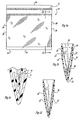
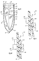
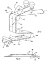
- the multi-layered bag 10 generally comprises an outer bag 12 and an inner liner 14.
- the outer bag 12 is defined by side sealed edges 18 and 18' as well as a folded edge 20 occurring along a first end (bottom) 22 of the outer bag.
- a reusable closure 16 is provided along a second end (top) 24 of the outer bag.
- the inner liner 14 includes side edges 26 and 26', which according to the embodiment of Fig. 1a, share a common edge seal with the outer bag as illustrated by reference numerals 18 and 18'.
- free standing (not sealed) or may be the side edges 26 and 26' of the inner liner may be sealed separately from the side edges of the outer base as demonstrated in Fig. 1e.
- the inner liner 14 includes two sidewalls 32 and 32' which are formed upon slitting the inner liner 14, the first ends 30 and 30' of the two sidewalls 32 and 32' are sonically welded or otherwise attached to the inner surfaces 34 and 34' of the outer bag 12. As illustrated, while not required, it is preferable that the sidewalls 32 and 32' generally extend almost the entire length of the multi-layered bag 10.
- the inner liner is shown to be perforated at lateral lines x and z occurring along the crotch 40 such that upon exerting sufficient pressure on the inner liner, the liner is torn along at least one of the perforation lines such that the sidewalls 32 and 32' are no longer continuous as shown most clearly with reference to Fig. 1d.
- the inner liner is generally separable from the side walls 36 and 36' of the outer bag 12 except for those embodiments wherein common edge seals are employed. As will be illustrated with regard to additional figures contained herein, as the closure 16 is pulled apart to form an opening 38 foodstuffs are placed into the multi-layered bag between the layers 32 and 32'.
- closures 16 which may be employed, examples of preferred reusable closures and information on their manufacture can be found in U.S. Patent Nos. 4,561,109; 4,363,345; 4,528,224; 5,070,854 and 5,804,265, all of which are hereby incorporated by reference.
- Other possible closure systems include adhesives, velcro, mechanical closures, slide lock closures, draw string with string or tape, fold lock top, magnetic closures, dead fold closures (i.e., aluminum foil, wire folded, tape), heat seals, staples, handle strings, cable ties or twist ties, among others.
- vent holes which were noted as being preferable according to U.S. Patent No. 5,804,265, can be eliminated. As such, air which can be trapped between the inner and outer bags of the aforementioned patent is no longer a concern.
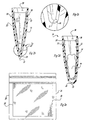
- FIGs. 2a - 2e an alternative multi-layered bag in accordance with the teachings of the present invention is shown. It should be noted that the same reference numerals will be utilized for identical components described under the embodiments of Figs. 1a - 1e and 2a - 2e, respectively.
- the crotch 40 of Figs. 1a - 1e includes a single lateral perforation line x.
- the crotch 40 of Figs. 1a - 1e includes multiple lateral perforation lines x and z respectively, provided along an excess of inner liner material.
- the lateral side seals between the outer bag and inner liner may be common or spaced apart.
- the perforation line x becomes tom to provide the separated sidewalls 32 and 32' of the inner liner 14.
- the first end 22 of the multi-layered bag 10 will generally conform to the shape of the foodstuff, i.e., become more rounded.
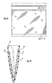
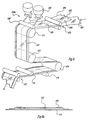
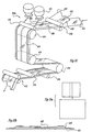
- FIGs. 3a - 3c still another multi-layered bag in accordance with the teachings of the present invention is illustrated.
- the outer bag 12 is essentially the same as disclosed with regard to the previously discussed embodiments.
- first end 30 of the inner liner 14 is the only portion which is attached to the inner surface 34 of the outer bag.
- the second end 30' is free standing.
- the length of the inner liner is sufficiently long so that second end 30' of the inner liner approaches the second end 24 of the multi-layered bag.
- the foodstuff be stored with the bag laying horizontally with the first sidewall 36 of the outer bag being disposed against the refrigerator or freezer bottom (not shown).
- the inner liner 14 may substantially conform to the shape of the foodstuffs thereby protecting against undesirable conditions such as freezer burn, for example.
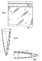
- a still further embodiment of the multi-layered bag is shown.
- Disposed within outer bag 12 is a truncated inner liner 14 which is attached along a first end 30 to the inner wall 34 of the outer bag.
- the free end 30' of the inner liner terminates in proximity to the first end (bottom) 22 of the outer bag.
- the inner liner 14 may conform generally to the shape of the foodstuff 44 which is highly desirable.
- Fig. 4a illustrates that the inner liner 14 may share a common side seal along one or both sidewalls with the outer bag, it is also possible that the inner liner 14 suspends freely within the outer bag excepting for the attachment 30.
- the inner liner 14 preferably includes a textured surface 50.
- the liner By texturing or embossing the film of the inner liner, the liner exhibits improved performance attributed to an increase in the surface area of the film which in turn provides greater cling to the foodstuff surface than is exhibited by a smooth film. Additionally, this texturing or embossing effectively reduces the overall stiffness of the inner liner which improves cling as well.
- the textured or embossed patterns as herein described also provide channeling of air away from the foodstuff as the inner liner comes in contact with the foodstuff, thus further conforming to the shape of the foodstuff.
- the density of the textured elements which are typically in a specific pattern may be from about 6 to 50 units per linear inch of the surface of the inner liner and preferably from about 10 to about 20 units per linear inch of the surface of the liner.
- the textured surfaces will generally include a plurality of protrusions which extend inwardly. Various geometrically shaped protrusions are further illustrated with reference to Figs. 6a - 6f.
- the method of attaching the inner liner to the outer bag may be any method which is known in the art, i.e., mechanical and/or adhesive, for example.
- the inner liner may, for example, be attached continuously and uniformly along the top edges or attached in a discontinuous or intermittent manner along the top edges.
- Useful examples of attaching the inner liner include by way of non-limiting example, hot air seam sealing, extrusion lamination, heated bar heat sealing, ultrasonic sealing, heated rollers or belt, adhesive film strips, infrared scaling, radio frequency sealing or vibration welding, by way of non-limiting example.
- the inner liner may also be attached to the support bag during manufacture by post applying closure profiles onto and over edges of the inner liner.
- a hinge type blanket seal as illustrated with reference to Figs. 5c and 5d. This so-called hinge type blanket seal is described in detail in U.S. Patent No. 5,804,265 which has been incorporated by reference.
- the outer support bag and inner liner of the multi-layered bags of the present invention are made from a thermoplastic material or a blend of thermoplastic materials and can be comprised of the same or different material.
- the films may be made by a conventional cast or blown film process.
- thermoplastics include, for example, polyolefins such as high density polyethylene (HDPE), low density polyethylene (LDPE), linear low density polyethylene (LLDPE), and polypropylene (PP); thermoplastic elastomers such as styrenic block copolymers, polyolefin blends, elastomeric alloys, thermoplastic polyurethanes, thermoplastic copolyesters and thermoplastic polyamides; polymers and copolymers of polyvinyl chloride (PVC), polyvinylidene chloride (PVDC), saran polymers, ethylene/vinyl acetate copolymers, cellulose acetates, polyethylene terephthalate (PET), ionomer (Surlyn), polystyrene, polycarbonates, styrene acrylonitrile, aromatic polyesters, linear polyesters, thermoplastic polyvinyl alcohols and useful materials listed hereinbefore that may be used to make an inner film layer.
- the outer support bag and the liner bag are both made of polyethylene and more preferably from a blend of low density polyethylene (LDPE) (about 0.92 density) and linear low density polyethylene (LLDPE) (about 0.925 density).
- LDPE low density polyethylene
- LLDPE linear low density polyethylene
- the inner liner film has a density of less than 0.930 g/cc.
- the film of the inner liner has a Transverse Direction 2 Percent Secant Modulus (TDSM) of less than 40,000 pounds per square inch (psi) (2.75 x 10 8 Pa) and preferably less than 27,000 psi (1.86 x 10 8 Pa) as determined in accordance with ASTM D 832-83, Method A with a jaw gap of 4 inches, a specimen width of 1 inch, an initial strain rate of 0.25 inches/inch/minute, and a crosshead speed of 1 inch/minute.
- the modulus of a film in either the transverse or machine direction of the film is generally a measurement of the stiffness of the film.
- thermoplastic polyolefin films that are prepared by cast film processes that are known in the art have a TDSM of from about 20,000 to about 40,000 psi.
- TDSM TDSM
- examples of commercially available resins that would result in cast or blown films having these tensile properties include, for example, LDPE 748 and LDPE 690 from The Dow Chemical Company.
- the inner liner has a Z number of less than 60,000 mil 3 psi.
- the inner liner has a Z number of less than 20,000 mil 3 psi more preferably from about 2,000 to about 10,000 mil 3 psi and, even more preferably, from about 3,000 to about 6,000 mil 3 psi.
- the outer support bag has a Z value in a range of from about 50,000 to about 150,000 mil 3 psi 5.6 to 16.9 mm 3 .kPa).
- the outer support bag will have a nominal sidewall thickness of from about 1 to about 4 mils, preferably from about 1.3 to about 3.0 mils and, more preferably, from about 1.5 to about 2.0 mils.
- Nominal thickness refers to the thickness of the film prior to any surface treatment such as scoring, texturing, embossing and the like.
- the inner liner will have a nominal sidewall thickness of from about 0.3 to about 1.0 mil and preferably has a nominal sidewall thickness of from about 0.5 to about 0.7 mil.
- the inner surface of the inner liner has a contact angle in the range of from 65° to 75° at 20° C relative to raw beef meat juice as determined by advancing contact angle determination using a contact goniometer f, for example, Model No. A-100, available from Rame-Hart.
- Contact angle is defined as the angle formed between a horizontal substrate and a line tangent to the surface of a drop of liquid at the point where the surface of the liquid drop meet the horizontal substrate.
- the contact angle is a function of the surface tension of the liquid.
- the lower degree of contact angle indicates a higher degree of wetting or adhesion of the liquid to the substrate.
- the method of measuring the contact angle is as follows: 1) drops of the liquid to be measured (about 1 microliter) are placed on the measuring surface (liner bag film) of the contact goniometer; 2) The contact angles are measured on both sides of each of five drops; 3) Step two is repeated on different sections of the inner surface and the results are averaged to determine a mean contact angle.
- Examples of film that have a contact angle of between 65° to 75° at 20° C relative to a raw beef meat juice include a blend of LDPE and LLDPE available from The Dow Chemical Company.
- the multi-layered bag of the present invention may also be made of films having different colors so to highlight the liner within a bag structure to the consumer.
- the inner liner and support bag may be of a different color or tint or each or both may be opaque or clear.
- the multi-layered bag of the present invention may also contain an inner liner and/or an outer bag that comprises a film or substrate that has been corona treated to improve the wetting characteristic of the film and thereby improve the meat adhering and/or printing characteristic of the film.
- the inside surface or food contacting surface of the inner liner is corona treated.
- the multi-layered bags of the present invention may also have a printed area on the support and/or the inner liner. Printed areas are used as a write-on surface or a write-on patch to record information relating to the contents of the bag.
- the means by which the multi-layered bags of the present invention prevent freezer burn of meats is that the inner liner film clings and conforms to the surface of the meat and therefore prevents moisture loss and excludes air from the meat surface. Excluding moisture loss and air from the meat surface reduces the formation of ice crystals that lead to freezer burn or dehydration of the meat.
- a diagrammatic flow diagram for carrying out a process of manufacturing multi-layered bags in accordance with the teachings of the present invention is provided.
- the inner liner film or second film may be extruded or supplied from an unwind stand.
- Extrusion of the liner film may be by blown or cast extrusion of thermoplastic material as is known in the art.
- Step illustrated by box 310 provides that the support or first thermoplastic film is extruded having zipper type closure profiles on each respective film edge.
- the extrusion may be either convention cast or blown film.
- An example of an integral cast film process is described in U.S. Patent No. 4,263,079, incorporated herein by reference.
- both of the films are cast extruded.
- the inner film may be slit or perforated wherein the inner liner is formed from a single sheet.
- the inner or second film is added or overlaid onto the first film.
- the second film is aligned such that the edges of the second film are between the closure profiles of the first film.
- the overlaying and alignment of the second film onto the first film is done using conventional guide means such as rollers and nip rolls.
- the parallel edges of the liner or second film are heat sealed to the support or first film.
- the films may be heat sealed together using conventional heat sealing means such as a heated bar sealer, a hot air sealer, extrusion lamination, heated rollers and belts and the like.
- step illustrated by box 340 the attached films web is folded and the closure profiles are joined.
- the web may be folded by conventional folding means known in the art.
- step illustrated by box 350 the folded film web is seal cut to form bags, the bags are stacked and the stacked bags are packed into a container.
- the attached films may be folded and seal cut into bags as described in U.S. Patent No. 5,062,825, incorporated herein by reference.
- the male and female closure elements are interlocked after folding of the films and prior to seal cutting.
- the finished bags may be stacked, delivered and then packed into containers as described in U.S. Patent Nos. 5,302,080; 5,108,085 and 5,185,987, incorporated herein by reference.
- Either one or both of the first and second films may be textured by, for example, embossing. Either or both of the film webs may be corona treated prior to or after being attached together.
- the second thermoplastic film is corona treated and embossed prior to overlaying the second film onto the first thermoplastic film.
- the second or liner film web may be perforated or slit prior to being overlaid onto the first or support film web using a process and an apparatus similar to that described in U.S. Patent No. 5,405,561.
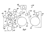
- FIG. 8 An apparatus employed to carry out a preferred process for making the film web used for making multi-layered bags of the present invention is shown in Fig. 8 and an apparatus for attaching the two film webs is shown in Fig. 9.
- Fig. 8 is a schematic side view of the process providing and attaching film webs 400
- Fig. 9 is an isometric view of a process for attaching the film webs together prior to forming bags.
- process 400 generally comprises a means for providing a support or first film web 410, a means for providing a liner or second film web 430, tension control means 440, means for perforating or slitting the second film web at 460 and a sealing or attaching means shown generally as 450.
- Means 410 generally comprises an extrusion means 412 in extrusion alignment with a cast roll 416 to form a support or first film web 414.
- the means for providing the first film web may also be any means known in the art and may be an extrusion process as described in U.S. Patent No. 5,049,223.
- Film web 414 passes through a conventional gauge control means 418 to a corona treatment means 420 wherein the first film web 414 is corona treated as described hereinbefore, to prepare the film for later optional printing.
- a liner or second film web 432 is provided by a roll or unwind stand 431.
- the second film 432 may also be provided by a conventional blown or cast film process as is known in the art.
- the second film web has a transverse web width that is smaller than the transverse web width of the first film web 414.
- Film webs 414 and 432 are fed in to tension control means such as nip rolls 440 so as to match the strain of each of the films. Matching the strain of the films is described hereinafter in more detail.
- the second film web may be supplied in a pre-perforated roll as shown in Fig. 8, it is also possible to perforate or slit the web as it approaches the rollers 472 as shown in other embodiments.
- the first and second film webs 414 and 432 are aligned and overlaid at roll 434 forming web 436.
- Web 436 is fed into a sealing means shown generally as 450.
- Web 436 changes orientation at roll 438 and is fed into sealing means 450.
- Sealing means 450 generally comprises an extrusion means or extruder 452, roll 454 and compression roll 456. A preferred sealing means is shown in Fig. 8 and described below.
- Extruder 452 provides a sealing band 458.
- Sealing band 458 is fed onto web 436 and overlaps the parallel edge of liner or second film 432.
- the sealing band 458 on web 436 passes between roll 454 and compression roll 456 and forming a blanket seal.
- Extrusion means or extruder 456 provides closure profiles 460.
- Closure profiles 460 are attached to the opposed parallel edges of the first film 414 as described in U.S. Patent No. 5,049,223, forming a web having a blanket seal and closure profiles, web 462.
- Web 462 having closure profiles is then folded, sealed and cut, stacked and packed as shown and described in Fig. 7. Either or both of the film webs may be textured or corona treated as described hereinbefore.
- the second thermoplastic film or liner film may be attached to the first thermoplastic film or support film by means of an extruded blanket seal over or underlap the side edges of the liner film, hot air hem sealing, extrusion lamination (extruded thermoplastic film between the film layers), hot melt adhesive (placed over or under the edge of the top film layer), ultrasonic sealing, heated rollers or belts, adhesive film strips, infrared sealing, radio frequency sealing or vibration welding.
- an extruded blanket seal over or underlap the side edges of the liner film, hot air hem sealing, extrusion lamination (extruded thermoplastic film between the film layers), hot melt adhesive (placed over or under the edge of the top film layer), ultrasonic sealing, heated rollers or belts, adhesive film strips, infrared sealing, radio frequency sealing or vibration welding.
- the liner film is attached to the support film using an extruded hinge type blanket seal 97 as shown in Fig. 5c and hereinafter described.
- the process shown in Fig. 7
- Fig. 10 shows a process for attaching the second thermoplastic film web 432 to the first thermoplastic film web 414 and is indicated generally as process 450a.
- the second thermoplastic film web 432 is aligned with and overlaid onto a first thermoplastic film web 414 forming film web 436.
- the film webs pass between nip rolls 472 and pass under a sealing band extruder 452.
- a sealing band 458 of molten thermoplastic material is extruded onto the advancing webs in the machine direction so as to overlap the edge 470 of the second film web and thereby contact and attach to both film webs securing the films together.
- the attached film webs are fed through a set of compression or pinch rolls 454, 456 forming a blanket seal 459.
- a conventional second sealing band extruder is used to seal the opposite parallel edge of the second film web to the first film web.
- Film web 436 having a blanket seal 459 then passes through conventional guide rolls 474 and 476 so to orient the web 436 for folding and seal cutting to form bags.
- the blanket seal 459 may be either a hinge type blanket seal 97 (Fig. 5c) or a heat seal type blanket seal 110 (Fig. 5d).
- Some of the advantages of the blanket sealing process include films may be attached continuously at a relatively high process rate, the blanket seal appears strong and aesthetically pleasing to consumers, the process is insensitive to other process variations and it does not produce a film tail as does other processes known in the art.
- the sealing bands may be applied in any fashion so as to attach the two films together.
- the first thermoplastic film has mateable male and female closure elements along opposing edges of the film web and the sealing bands are applied equidistant from their respective closure profiles. More preferably, the sealing bands are applied equidistant from the respective edges of the first thermoplastic film such that mateable male and female closure elements may be applied to the support or first thermoplastic film after the film webs are attached.
- the sealing band may be made from any suitable thermoplastic material or combination of thermoplastic materials that are heat sealable to at least the portions of the thermoplastic films to be joined.
- the sealing band is polyethylene and , more preferably, low density polyethylene.
- An example of a suitable commercially available LDPE useful in the present invention is LDPE 748, commercially available from the Dow Chemical Company.
- the width of the sealing band may generally range from about 3 mm to the width of the support or first film web.
- the width of the sealing band ranges from about 3 to about 76 mm and, more preferably, has a width of from about 6 to about 19 mm.
- the sealing band used to form a hinge type blanket seal has a thickness of from about 13 to 254 microns (0.5 to 10 Mils) and preferably has a thickness of from about 25 to about 51 microns (1 to 2 mils) and more preferably from about 25.5 microns to about 38.2 microns (1.0 to 1.5 mils).
- the sealing bands may be tinted, colored or textured so to highlight the liner within a bag structure to the consumer.
- the sealing band normally does not heat seal the second film to the first film, the sealing band may advantageously be used to attach films that otherwise could not be heat sealed together. However, if the sealing band temperature, heat capacity and mass are sufficient and the liner film has an appropriate thickness and sealing temperature, the extruded sealing band will transfer enough heat through the liner film to heat seal it to the support film.
- the width of the liner or second film web is less or smaller than the width of the first film web so that any portion of the seal band does not hang over the edge of the first film web after being applied.
- the width of the liner or second film is smaller than that of the width of the first film such that male and female closure profiles may be attached along opposed parallel edges of the first film web.
- Poisson's ratio is a ratio of lateral strain to axial strain and is typically about 0.3 for polyethylene.
- the puckering can be minimized by a variety of means, including attaching webs that are similar in modulus and/or attaching webs that are similar in Poisson's ratio.
- the puckering can be minimized by running at low tension where the films are attached so there will be less recovery.
- the cross direction puckering can sometimes be considered insignificant compared to the machine direction.
- a recommended tension in the machine direction range to effectively transport webs is from 10 - 25% of the yield tension, measured in PLL film tracking may become less precise at tensions below 10% of the yield tension.
- the MD tension in each web can be maintained from 0 - 100% of the yield point, it has been found that above 25% of the yield point, there is a danger of localized thin spots in the web actually exceeding the yield point of the film, resulting in non-elastic stretching. It has been found that for successful attachment of extruded sealing bands, the tension is preferably run in the range of 2 - 15% of the yield tension in the machine direction.
- the embodiment shown in Fig. 9 has a set of nip rolls between the two web supply points and the point where a blanket seal is applied. Then the tension in the two webs can be matched at somewhat higher, for example, 15% of the yield point tension prior to the nip rolls. Nip rolls allow different tension control zones.
- the strain in the webs can be matched by appropriate tension control between the supply points and the nip roll.
- the compression roll is run at slightly lower speed that the nip rolls so to release some of the MD tension, reducing it to the desired 2 - 15% range for blanket band sealing.
- a second set of nip rolls could optionally be added such that each web would run through a separate nip and could have separate tension control just prior to joining of the separate film webs as shown in Fig. 8.
- the tension of the liner or second thermoplastic film is generally controlled in the range of from about 0.05 to about 1 pound per linear inch width (PLI) (0.6 mil PE) by using a set of compressing or nip rollers 440 as is known in the art.
- PLI pound per linear inch width
- each of the film webs pass through nip rolls so to match the strain on each of the films.
- the tension of each of the film webs may be different in order to match the strain on each of the films.
- Alignment of the liner or second film may be accomplished by using conventional edge guiding systems and/or edge trimming of the film web to width.
- the tension of the combined films is generally controlled in the range of from about 0.02 to about 2.0 PLI (PE films) after the sealing band is applied to avoid stretching of the warm bands.
- the tension of the combined film webs may be controlled by conventional nip rollers 472. Stretching of the blanket bands may produce a "wave" and/or puckering in the final product.
- an alternate process according to the present invention for heat sealing at least two film webs comprises the steps of providing at least first and second film webs capable of being heat sealed together, overlaying the second film web onto the first film web, providing at least one sealing band of material having a temperature, mass and heat capacity sufficient to heat seal the second thermoplastic film to the first thermoplastic film and applying said band of sealing material to the overlaid film webs.
- This process is the same as the process shown in Fig. 8 except that the sealing band extruder 452 may be placed above any portion of the film web 436 so to heat seal the film webs together in the machine direction at any point across the web.
- the sealing band is compressed between rollers 454, 456 after having been applied.
- Multiple sealing band extruders 452 are used to provide multiple sealing bands 458 along the machine direction of the film web so as to form multiple heat seal type blanket bands as shown in Fig. 5d.
- the film webs may be provided by extrusion or from an unwind stand.
- the film webs to be heat sealed may be made of any thermoplastic materials capable of being heat sealed together including those materials described hereinbefore.
- the film webs may have the same width or be of different widths.
- the sealing band may be made of any extrudable material capable of heat sealing to film webs together.
- the sealing band is made from thermoplastic materials including, for example, LDPE 748, available from The Dow Chemical Company.
- the sealing band has a temperature, heat capacity and mass sufficient to heat seal two films together.
- the temperature of the sealing band is the temperature at which the particular material may be extruded without degrading.
- the thickness of the film to be heat sealed should be of a thickness so as to allow heat transfer from the sealing band to the film to heat seal the film to the underlying film web.
- the thickness of the sealing band used to form a heat seal type blanket seal may range from about 0.5 to about 10 mil.
- the sealing band for a heat seal type blanket seal has a thickness of from about 1.5 to about 3.0 mil and, more preferably, has a thickness of from about 1.5 to about 2 mil.
- the width of the sealing band used to form a heat seal type blanket seal ranges from about 3 mm to the width of the support or first film web, preferably the width of the sealing band ranges from about 3 to about 76 mm and, more preferably, has a width of from about 6 to about 19 mm.
- the second film 432 of the resulting panel is bonded underneath the respective blanket seals 459.
- another process according to the present invention for attaching at least two film webs comprises the steps of providing at least first and second film webs having first and second widths respectively, the second width being smaller than the first width, optionally perforating or slitting the second film, overlaying the second film web onto the first film web between parallel edges of the first film web, providing at least one band of sealing material and applying said band of sealing material along and over parallel edges of the second film web.
- the sealing band 458 is applied to the fill webs by one or more extruders 452.
- Extruders 452 may be placed at any point above the film webs so to be capable of attaching the film webs together by forming a hinge type blanket seal in the machine direction.
- multiple extruders 452 may be staggered above the parallel edges of three or more film webs so to attach the film webs together in succession.
- the sealing band 452 is compressed between rollers 454, 456 after having been applied to the parallel edges of the film web or webs.
- the sealing bands 458 used to form hinge type blanket seals are applied equidistant from the respective edges of the first thermoplastic film.
- the sealing band may be made from any suitable thermoplastic material or combination of thermoplastic materials that are heat sealable to at least the portions of the film webs to be joined.
- the film webs to be joined may be, for example, thermoplastic as described hereinbefore, non-thermoplastic, fabrics, nonwoven, co-extruded films and the like.
- the film substrates are attached together by the sealing band as shown in Fig. 5c.
- the width of the sealing band may generally range from about 3 mm to the width of the support or first film web, preferably the width of the sealing band ranges from about 3 to about 76 mm and, more preferably, has a width of from about 6 to about 19 mm.
- the sealing band used to form a hinge type blanket seal has a thickness of from about 13 to about 254 microns (0.5 to 10 mils) and, preferably, has a thickness of from about 25 to about 51 microns (1 to 2 mils) and, more preferably, from about 25.5 microns to about 38.2 microns (1.0 to 1.5 mils).
- the multi-layered bag is substantially similar to that of Fig. 8 except that the inner liner 432 is in the form of a single perforated sheet having an enlarged web width.
- the sheet or film, as it is otherwise referred to, is folded over as it advances through rollers 472 to be subsequently tom along the perforations.
- the inner liner is formed from two separate and distinct sheet rolls rather than a single sheet which is perforated or slit. As the two sheets are advanced through rollers 472, the sheets are overlapped as demonstrated most clearly in Fig. 11b.
Landscapes
- Engineering & Computer Science (AREA)
- Mechanical Engineering (AREA)
- Bag Frames (AREA)
- Making Paper Articles (AREA)
- Packages (AREA)
- Packging For Living Organisms, Food Or Medicinal Products That Are Sensitive To Environmental Conditiond (AREA)
Claims (26)
- Mehrlagiger Beutel (12) mit einem Außenbeutel (12) und mindestens einer Innenauskleidung (14), wobei der Außenbeutel (12) zwei Seitenflächen (36, 36') jeweils mit einer Innenseite (34, 34') und einer Außenseite hat und die Seitenflächen (36, 36') entlang zugehöriger Seitenkanten (18, 18'), die die Öffnung des mehrlagigen Beutels (10) bilden, und einer gefalteten Kante (20) zusammengefügt sind, die den Boden des mehrlagigen Beutels (10) bildet, wobei die Innenauskleidung (14) mindestens eine Seitenfläche (32, 32') mit einer oberen Kante (30, 30') aufweist, die an die Innenseite (34, 34') des Außenbeutels (12) angesetzt ist,
dadurch gekennzeichnet, dass die mindestens eine Seitenfläche der Innenauskleidung (14) mindestens eine freie Kante aufweist. - Mehrlagiger Beutel nach Anspruch 1, bei dem die oberste Kante (30, 30') der Innenauskleidung (14) an die Innenseite (34, 34') des Außenbeutels (12) angesetzt und von der Öffnung des mehrlagigen Beutels beabstandet ist.
- Mehrlagiger Beutel nach Anspruch 1, bei dem die Seitenflächen (32, 32') der Innenauskleidung eine Nenndicke von 0,3 bis 1,0 mils haben.
- Mehrlagiger Beutel nach Anspruch 3, bei dem die Innenauskleidung (14) eine thermoplastische Folie mit einem 2%-Secantmodul in Querrichtung (TDSM) von weniger als 40.000 psi nach ASTM D 832-83, Methode A, bei einem Backenspalt von 4 in. für Proben mit 1 in. Breite aufweist, außer dass die Anfangs-Verformungsrate 0,25 in./in./min. bei einer Quer-Kopfgeschwindigkeit von 1 in./min. beträgt.
- Mehrlagiger Beutel nach Anspruch 4, bei dem die Innenauskleidung (14) eine thermoplastische Folie mit einer Z-Zahl von weniger als 60.000 mil3psi aufweist, wobei Z = (t3) x (TDSM), t die Foliendicke in mils und TDSM der Secantmodul in Querrichtung nach ASTM D 83283, Methode A, bei einem Backenspalt von 4 in. für Proben mit 1 in. Breite ist, außer dass die Anfangs-Verformungsrate 0,25 in./in./min. bei einer Quer-Kopfgeschwindigkeit von 1 in./min. beträgt.
- Mehrlagiger Beutel nach Anspruch 5, bei dem die Z-Zahl der Innenauskleidung niedriger als 20.000 mil3psi ist.
- Mehrlagiger Beutel nach Anspruch 3, bei dem der Außenbeutel (12) eine Folie mit einem Z-Wert im Bereich von 50.000 bis 150.000 mil3psi aufweist.
- Mehrlagiger Beutel nach Anspruch 7, bei dem die Innenauskleidung (14) eine thermoplastische Folie aus Ethylen-Homo- und Copolymerisaten aufweist.
- Mehrlagiger Beutel nach Anspruch 1, bei dem die oberste Kante (30, 30') der Innenauskleidung (14) mit einem Scharnier- oder einem Aufschweiß-Abdeckverschluss an eine Seitenfläche (36, 36') des Außenbeutels (12) angesetzt ist.
- Mehrlagiger Beutel nach Anspruch 1, dessen Innenauskleidung (14) texturiert ist.
- Mehrlagiger Beutel nach Anspruch 1, dessen Außenbeutel (12) entlang gegenüberliegender Innenseiten komplementäre, in den gegenseitigen Eingriff bringbare Verschlusselement aufweist.
- Mehrlagiger Beutel nach Anspruch 11, dessen Innenauskleidung (14) entlang seitlicher Kanten der gemeinsamen Kantenverschlüsse zusätzlich an den Außenbeutel (12) angesetzt ist.
- Mehrlagiger Beutel nach Anspruch 12, bei dem die oberste Kante (30, 30') der Innenauskleidung (14) mit einem Abdeckverschluss an eine Seitenfläche des Außenbeutels angesetzt ist.
- Mehrlagiger Beutel nach Anspruch 13, bei dem die Innenseite der Seitenfläche der Innenauskleidung koronabehandelt ist.
- Mehrlagiger Beutel nach Anspruch 1, bei dem die Kantenverschlüsse der Innenauskleidung von den Kantenverschlüssen des Außenbeutels getrennt vorliegen.
- Mehrlagiger Beutel nach Anspruch 1, bei dem die oberste Kante (30, 30') der Innenauskleidung (14) mit einem Heißschmelzklebstoff oder einem Heißluft-Saumverschluss an eine Seitenfläche (36, 36') des Stützbeutels angesetzt ist.
- Mehrlagiger Beutel nach Anspruch 1, dessen Innenauskleidung (14) eine Farbe hat, die sich von der mindestens eines Teils des Stützbeutels (12) unterscheidet.
- Mehrlagiger Beutel nach Anspruch 1, dessen Innenauskleidung (14) ein erstes Blatt, das entlang der Innenseite einer ersten Seitenfläche angesetzt ist, und ein zweites Blatt aufweist, das entlang der Innenseite einer zweiten Seitenfläche angesetzt ist, wobei das erste und das zweite Blatt diskontinuierlich sind.
- Verfahren zum Herstellen eines mehrlagigen Beutels mit einem Außenbeutel (12) und einer Innenauskleidung (14), das folgende Schritte aufweist:dadurch gekennzeichnet, dass die zweite thermoplastische Folienbahn (432) als separate erste und zweite aneinandergrenzende Bahn oder als eine einzige Bahn bereit gestellt werden, in welchem Fall der Schritt eines Perforierens oder Schlitzens der zweiten thermoplastischen Folie (432) hinzutritt, um auf einer Auskleidungslage des fertigen mehrlagigen Beutels eine freie Kante auszubilden.Heranführen einer ersten thermoplastischen Folienbahn (414) einer Dicke von mehr als 1 mil (25,4µm) und einer ersten Bahnbreite in Querrichtung zwischen parallen Kanten;Heranführen mindestens einer zweiten thermoplastischen Folienbahn (432) einer Dicke von weniger als 2 mils (50,8 µm) und einer zweiten Bahnbreite in Querrichtung zwischen parallelen Kanten, wobei die zweite Quer-Bahnbreite kleiner ist als die Breite der ersten thermoplastischen Folie (414);Auflegen der zweiten thermoplastischen Folienbahn (432) auf die erste thermoplastische Folienbahn (414) zwischen den parallelen Kanten der letzteren;Ansetzen der zweiten thermoplastischen Folienbahn (432) an die erste thermoplastische Folienbahn (414) entlang paralleler Kanten der zweiten thermoplastischen Folienbahn (432);Falten der Folienbahnen (414, 432) in Querrichtung; undVerschließen und Zertrennen der gefalteten Folienbahnen (414, 432), um einen mehrlagigen Beutel auszubilden;
- Verfahren nach Anspruch 19 mit dem Schritt des Aufbringens in den gegenseitigen Eingriff bringbarer komplementärer Verschlusselemente (460) entlang gegenüber liegende paralleler Kanten der ersten thermoplastischen Folienbahn (414).
- Verfahren nach Anspruch 19, bei dem die Folien durch Aufbringen eines Scharnier-Abdeckverschlusses (459, 97) oder eines Aufschweiß-Abdeckverschlusses (459, 110) angesetzt werden.
- Verfahren nach Anspruch 19, bei dem die erste thermoplastische Folienbahn (414) entlang gegenüberliegender paralleler Kanten in den gegenseitigen Eingriff bringbare komplementäre Verschlusselemente (460) aufweist und die zweite thermoplastische Folienbahn (432) zwischen den Verschlusselementen (460) auf die erste thermoplastische Folienbahn (414) aufgelegt wird.
- Verfahren nach Anspruch 19, bei dem die zweite thermoplastische Folienbahn (432) koronabehandelt ist.
- Verfahren nach Anspruch 19, bei dem die zweiten thermoplastischen Folienbahnen (432) aus Polyethylen sind.
- Verfahren nach Anspruch 19, bei dem die Innenauskleidung (14) ein erstes Blatt, das entlang der Innenseite einer ersten Seitenfläche (36) angesetzt ist, und ein zweites Blatt aufweist, das entlang der Innenseite einer zweiten Seitenfläche (36') angesetzt ist.
- Vorrichtung zum Herstellen mehrlagiger Beutel mit mindestens einem inneren Auskleidungsbeutel und einem äußeren Stützbeutel, die aufweist:dadurch gekennzeichnet, dass entweder eine Einrichtung zum Perforieren oder Schlitzen der zweiten Folienbahn in Längsrichtung vorgesehen ist oder die zweite thermoplastische Folienbahn zwei getrennte aneinandergrenzende Blätter aufweist, um auf mindestens einer Seite der Auskleidung von mittels der Vorrichtung gefertigten mehrlagigen Beuteln eine freie Kante auszubilden.eine Einrichtung (410) zum Heranführen einer ersten thermoplastischen Folienbahn (414) mit einer Dicke von mehr als 1 mil (25,4 µm) und einer ersten Bahnbreite in Querrichtung zwischen paralleler Kanten;eine Einrichtung (430) zum Heranführen mindestens einer zweiten thermoplastischen Folienbahn mit einer Dicke von weniger als 2 mils (50,8 µm) und eine zweiten Bahnbreite in Querrichtung zwischen parallelen Kanten, wobei die zweite Quer-Bahnbreite kleiner ist als die Breite der ersten thermoplastischen Folie;eine Einrichtung (434) zum Auflegen der zweiten thermoplastischen Folienbahn (432) auf die erste thermoplastische Folienbahn (414) zwischen parallelen Kanten der ersten thermoplastischen Folie;eine Einrichtung zum Falten der Folien in Querrichtung; undeine Einrichtung zum Verschließen und Zertrennen der gefalteten Folien zu Beuteln;
Applications Claiming Priority (3)
| Application Number | Priority Date | Filing Date | Title |
|---|---|---|---|
| US09/324,474 US6371643B2 (en) | 1999-06-02 | 1999-06-02 | Multi-Layered freezer storage bag |
| US324474 | 1999-06-02 | ||
| PCT/US2000/015244 WO2000072651A2 (en) | 1999-06-02 | 2000-06-02 | Multi-layered freezer storage bag |
Publications (2)
| Publication Number | Publication Date |
|---|---|
| EP1181196A2 EP1181196A2 (de) | 2002-02-27 |
| EP1181196B1 true EP1181196B1 (de) | 2005-03-02 |
Family
ID=23263749
Family Applications (1)
| Application Number | Title | Priority Date | Filing Date |
|---|---|---|---|
| EP00936470A Expired - Lifetime EP1181196B1 (de) | 1999-06-02 | 2000-06-02 | Mehrschichtiger gefrierlagersack |
Country Status (18)
| Country | Link |
|---|---|
| US (1) | US6371643B2 (de) |
| EP (1) | EP1181196B1 (de) |
| JP (1) | JP2003500299A (de) |
| KR (1) | KR100396419B1 (de) |
| CN (1) | CN1183008C (de) |
| AR (3) | AR026127A1 (de) |
| AT (1) | ATE289945T1 (de) |
| AU (1) | AU751499B2 (de) |
| BR (1) | BR0011255A (de) |
| CA (1) | CA2374321C (de) |
| DE (1) | DE60018411T2 (de) |
| ES (1) | ES2234610T3 (de) |
| HK (1) | HK1047916A1 (de) |
| MX (1) | MXPA01012361A (de) |
| NZ (1) | NZ515931A (de) |
| TW (1) | TW498043B (de) |
| WO (1) | WO2000072651A2 (de) |
| ZA (1) | ZA200110063B (de) |
Families Citing this family (69)
| Publication number | Priority date | Publication date | Assignee | Title |
|---|---|---|---|---|
| KR100349516B1 (ko) * | 2000-02-25 | 2002-08-22 | 주식회사 제로팩 | 진공포장지 |
| FR2810640B1 (fr) * | 2000-06-22 | 2003-05-30 | Soplaril Sa | Emballage avec systeme de fermeture par bande, procede pour sa fabrication |
| US20090208147A1 (en) * | 2002-06-06 | 2009-08-20 | Mark Steele | Multi-compartment flexible package |
| US20040031244A1 (en) * | 2002-06-06 | 2004-02-19 | Mark Steele | Multi-compartment flexible package |
| US20090238499A1 (en) * | 2002-06-06 | 2009-09-24 | Mark Steele | Multi-compartment flexible package |
| US6939040B2 (en) * | 2002-11-07 | 2005-09-06 | Illinois Tool Works Inc. | Reclosable package having film that curls or bends away from slider |
| US20050069227A1 (en) * | 2003-09-29 | 2005-03-31 | Mark Steele | Flexible package having integrated slit member |
| US20050254731A1 (en) * | 2004-05-14 | 2005-11-17 | Curwood, Inc. | Easy-open handle bag for medium to heavy duty applications |
| US7850368B2 (en) | 2004-06-04 | 2010-12-14 | S.C. Johnson & Son, Inc. | Closure device for a reclosable pouch |
| US20050286817A1 (en) * | 2004-06-28 | 2005-12-29 | Hall Bruce N | Storage bag |
| US7290660B2 (en) * | 2004-07-23 | 2007-11-06 | Tilman Paul A | Storage system having a disposable vacuum bag |
| US20070172157A1 (en) * | 2004-07-23 | 2007-07-26 | Alcoa Inc. | Polymeric package with resealable closure and valve and methods relating thereto |
| US20070092167A1 (en) * | 2005-10-24 | 2007-04-26 | Paul Tilman | Polymeric Package With Resealable Closure And Valve, And Methods |
| US7422369B2 (en) * | 2005-01-20 | 2008-09-09 | The Glad Products Company | Storage bag with fluid separator |
| US7597479B2 (en) * | 2005-01-20 | 2009-10-06 | The Glad Products Company | Storage bag with fluid separator |
| US20060216382A1 (en) * | 2005-03-23 | 2006-09-28 | Santa Cruz Cathy D | Container and process for prolonging the edible lifespan of a food product |
| US20070000800A1 (en) * | 2005-06-29 | 2007-01-04 | Masterchem Industries Llc | Storage system for a paint-wet paint roller cover |
| US20080256901A1 (en) * | 2005-10-24 | 2008-10-23 | Reynolds Foil Inc, D/B/A Reynolds Consumer Products Company | Polymeric package with resealable closure and valve, and methods |
| US20070110340A1 (en) * | 2005-11-17 | 2007-05-17 | Buchman James E | Tamper evident polymeric package with zipper closure and valve, and methods |
| JP2007166299A (ja) * | 2005-12-14 | 2007-06-28 | Sony Corp | 固体撮像素子、色分解撮像光学系及び撮像装置 |
| US7712962B1 (en) * | 2006-01-27 | 2010-05-11 | The Glad Produts Company | Storage bag |
| US7651579B1 (en) | 2006-01-27 | 2010-01-26 | The Glad Products Company | Storage bag |
| WO2007146649A2 (en) * | 2006-06-14 | 2007-12-21 | The Glad Products Company | Microwavable bag or sheet material |
| WO2007146650A2 (en) * | 2006-06-14 | 2007-12-21 | The Glad Products Company | Microwavable bag or sheet material |
| KR100817855B1 (ko) | 2006-07-18 | 2008-04-04 | 안영식 | 손잡이붙이 일회용 포장용기 |
| US7857514B2 (en) | 2006-12-12 | 2010-12-28 | Reynolds Foil Inc. | Resealable closures, polymeric packages and systems and methods relating thereto |
| US7886412B2 (en) | 2007-03-16 | 2011-02-15 | S.C. Johnson Home Storage, Inc. | Pouch and airtight resealable closure mechanism therefor |
| US7784160B2 (en) | 2007-03-16 | 2010-08-31 | S.C. Johnson & Son, Inc. | Pouch and airtight resealable closure mechanism therefor |
| US7887238B2 (en) | 2007-06-15 | 2011-02-15 | S.C. Johnson Home Storage, Inc. | Flow channels for a pouch |
| US7874731B2 (en) | 2007-06-15 | 2011-01-25 | S.C. Johnson Home Storage, Inc. | Valve for a recloseable container |
| US7857515B2 (en) | 2007-06-15 | 2010-12-28 | S.C. Johnson Home Storage, Inc. | Airtight closure mechanism for a reclosable pouch |
| US7967509B2 (en) | 2007-06-15 | 2011-06-28 | S.C. Johnson & Son, Inc. | Pouch with a valve |
| US7946766B2 (en) | 2007-06-15 | 2011-05-24 | S.C. Johnson & Son, Inc. | Offset closure mechanism for a reclosable pouch |
| US8517609B2 (en) * | 2007-07-19 | 2013-08-27 | Christopher W. Conner | Resizable food container |
| US20100212821A1 (en) * | 2007-09-24 | 2010-08-26 | Scodix, Ltd. | System and method for cold foil relief production |
| US9301520B2 (en) | 2007-12-21 | 2016-04-05 | Sartorius Stedim North America Inc. | Systems and methods for freezing, storing and thawing biopharmaceutical materials |
| US8177123B2 (en) * | 2008-09-24 | 2012-05-15 | Sartorius Stedim North America Inc. | Systems and methods for freezing, storing and thawing biopharmaceutical materials |
| US8540427B2 (en) * | 2008-03-07 | 2013-09-24 | Mark Steele | Gusseted package with impact barrier |
| US20110255809A1 (en) * | 2008-08-22 | 2011-10-20 | The Glad Products Company | Bag with Reinforcing Features |
| JP2010202280A (ja) * | 2009-03-04 | 2010-09-16 | Tomoyuki Kon | 緩衝性を有する封筒 |
| US20100237068A1 (en) * | 2009-03-17 | 2010-09-23 | Rubbermaid Incorporated | Container With In-Molded Exposed Panel |
| US9050783B2 (en) * | 2009-11-16 | 2015-06-09 | The Glad Products Company | Multi-layered bags with shortened inner layer |
| US20110164836A1 (en) * | 2010-01-05 | 2011-07-07 | Chen Yi-Min | Plastic bag with reinforced sides |
| US8550716B2 (en) | 2010-06-22 | 2013-10-08 | S.C. Johnson & Son, Inc. | Tactile enhancement mechanism for a closure mechanism |
| US11180286B2 (en) | 2010-10-29 | 2021-11-23 | S. C. Johnson & Son, Inc. | Reclosable bag having a loud sound during closing |
| US9327875B2 (en) | 2010-10-29 | 2016-05-03 | S.C. Johnson & Son, Inc. | Reclosable bag having a loud sound during closing |
| US8974118B2 (en) | 2010-10-29 | 2015-03-10 | S.C. Johnson & Son, Inc. | Reclosable bag having a sound producing zipper |
| JP3165722U (ja) * | 2010-11-11 | 2011-02-03 | 実 横内 | 紙製袋 |
| US9238536B2 (en) | 2011-01-21 | 2016-01-19 | S.C. Johnson & Son, Inc. | Method for providing consumers with a food storage kit |
| US8469593B2 (en) | 2011-02-22 | 2013-06-25 | S.C. Johnson & Son, Inc. | Reclosable bag having a press-to-vent zipper |
| US8568031B2 (en) | 2011-02-22 | 2013-10-29 | S.C. Johnson & Son, Inc. | Clicking closure device for a reclosable pouch |
| US20120305437A1 (en) * | 2011-06-01 | 2012-12-06 | Polyzen, Inc. | Digital appliance cover |
| US20130205721A1 (en) * | 2011-08-22 | 2013-08-15 | Duro Bag Manufacturing Company | Pouch Style Food Service Bag |
| US9403347B2 (en) | 2011-12-15 | 2016-08-02 | Berry Plastics Corporation | Peelable closure for container |
| US9387955B2 (en) * | 2012-01-25 | 2016-07-12 | The Glad Products Company | Multi-layered thermoplastic bag with reinforced seals and methods of making the same |
| US9315319B2 (en) * | 2012-01-25 | 2016-04-19 | The Glad Products Company | Continuous process for trash bag with inner bag |
| US9387957B2 (en) * | 2012-01-25 | 2016-07-12 | The Glad Products Company | Trash bag with inner bag |
| CA2884819C (en) * | 2012-03-06 | 2020-03-10 | The Glad Products Company | Multi-layered bags with shortened inner layer |
| IL247240A0 (en) * | 2016-08-09 | 2016-12-29 | Fertilizers & Chemicals Ltd | Fertilizer package and method for its production |
| CN107364635B (zh) * | 2017-06-30 | 2019-03-08 | 嘉兴华悦包装用品有限公司 | 具有制冷功能的食品包装拉链袋 |
| CN109205055A (zh) * | 2017-07-03 | 2019-01-15 | 广元公正科技有限公司 | 买冰冻产品的设备 |
| US11001429B2 (en) | 2017-08-16 | 2021-05-11 | Inteplast Group Corporation | Reinforced stand-up plastic storage bag |
| US20190092564A1 (en) * | 2017-09-22 | 2019-03-28 | Poly-America, L.P. | Polymeric bags and method to make same |
| JP2019069817A (ja) * | 2017-10-06 | 2019-05-09 | 宇部フィルム株式会社 | 鮮度保持用プラスチックフィルム及び包装材 |
| US20200138193A1 (en) * | 2018-05-14 | 2020-05-07 | Cubbler Scott | Multi-Layered Protective Covers and Methods for Making the Same |
| JP7268687B2 (ja) * | 2018-11-13 | 2023-05-08 | 王子ホールディングス株式会社 | 包装袋 |
| CN114144362B (zh) * | 2019-07-18 | 2023-09-05 | 格拉德产品公司 | 扩张型储存袋 |
| CN118786078A (zh) * | 2022-03-03 | 2024-10-15 | 阿姆科挠性物品北美公司 | 尺寸稳定的柔性可微波包装 |
| US20240100800A1 (en) * | 2022-09-22 | 2024-03-28 | Pregis Innovative Packaging Llc | Packaging with multi-ply walls |
Family Cites Families (82)
| Publication number | Priority date | Publication date | Assignee | Title |
|---|---|---|---|---|
| US2638952A (en) | 1950-04-29 | 1953-05-19 | Doris K Sanderson | Collapsible scrub bucket |
| FR1067272A (fr) * | 1952-11-28 | 1954-06-14 | Caoutchouc Et Derives | Perfectionnements apportés aux sacs en matière plastique |
| US3008862A (en) | 1956-06-29 | 1961-11-14 | Union Carbide Corp | Extruded bead sealing |
| CH359659A (de) * | 1958-07-12 | 1962-01-15 | Papro Ag Fuer Papierverarbeitu | Beutel und Verfahren zu dessen Herstellung |
| US3282412A (en) * | 1963-11-06 | 1966-11-01 | Wayne V Rodgers | Valved mixing container or package |
| FR1436217A (fr) * | 1965-04-15 | 1966-04-22 | Sachet d'emballage pour boissons et son procédé de fabrication | |
| US3494457A (en) | 1968-08-05 | 1970-02-10 | Dow Chemical Co | Abuse resistant bag |
| BE754507A (fr) | 1969-08-08 | 1971-02-08 | Dow Chemical Co | Procede d'emballage d'articles perfectionne |
| US3746215A (en) * | 1971-01-29 | 1973-07-17 | A Ausnit | Reclosable sealed pouring bag |
| US3762628A (en) * | 1971-05-17 | 1973-10-02 | Ppg Industries Inc | Coupon-confining bag, method and apparatus |
| US3734394A (en) | 1971-08-12 | 1973-05-22 | Milprint Inc | Flexible package with double layered walls |
| US3929275A (en) | 1972-07-07 | 1975-12-30 | Union Camp Corp | Bags with film liners and method of making |
| US3844409A (en) * | 1972-11-27 | 1974-10-29 | W Bodolay | Two compartment unitary bag having shelf |
| US4172152A (en) | 1974-02-21 | 1979-10-23 | Carlisle Richard S | Thermally insulative beverage container |
| US3945873A (en) | 1974-05-03 | 1976-03-23 | E. I. Du Pont De Nemours & Company | Process for bonding non-woven fibrous sheets and articles made therefrom |
| US3977596A (en) * | 1974-09-16 | 1976-08-31 | Bruce Gamble | Newspaper recycling apparatus |
| US4226330A (en) * | 1976-11-01 | 1980-10-07 | Butler Robert W | Rupture lines in flexible packages |
| DK147359C (da) | 1977-09-23 | 1985-01-28 | Gople Pack Ind Marketing Aps | Termisk isolerende pose, isaer en baerepose |
| US4481669A (en) | 1978-06-26 | 1984-11-06 | W. R. Grace & Co., Cryovac Div. | Multi-walled plastics bag |
| US4211297A (en) | 1978-08-08 | 1980-07-08 | Dunbar Glenn G | Weight vehicle apparatus |
| US4186786A (en) | 1978-09-29 | 1980-02-05 | Union Carbide Corporation | Colored interlocking closure strips for a container |
| US4211091A (en) | 1979-02-23 | 1980-07-08 | Campbell June H | Insulated lunch bag |
| US4256256A (en) * | 1979-04-30 | 1981-03-17 | American Can Company | Multiple compartment pouch and method of making same |
| US4358466A (en) | 1980-04-11 | 1982-11-09 | The Dow Chemical Company | Freezer to microwave oven bag |
| US4323586A (en) | 1980-10-20 | 1982-04-06 | Ludlow Corporation | Thermally-processable flexible package and process for using same |
| GB2097361A (en) | 1981-01-09 | 1982-11-03 | Addison C K & Co Ltd | Bag |
| AU543694B2 (en) * | 1981-03-18 | 1985-04-26 | Johnsen & Jorgensen Jaypak Ltd. | Bag and bag making apparatus |
| US4428788A (en) | 1982-05-14 | 1984-01-31 | Union Carbide Corporation | Film-tape-closure device slot cast integrated interlocking structure and extrusion method |
| US4411919A (en) | 1982-08-16 | 1983-10-25 | W. R. Grace & Co., Cryovac Division | Meat adhearing cook-in packaging |
| US5020922A (en) | 1983-06-30 | 1991-06-04 | W. R. Grace & Co.-Conn. | Bone puncture resistant bag |
| US4479010A (en) | 1983-07-20 | 1984-10-23 | Texaco Inc. | Procedure for the alkoxylation of polyoxyalkyleneamines |
| NL8400578A (nl) | 1984-02-24 | 1985-09-16 | Wavin Bv | Kunststofzak met in de zakfoliewand door middel van laserstraling aangebrachte perforaties alsmede kunststoffolie geschikt voor toepassing bij een dergelijke kunststofzak. |
| US4735308A (en) | 1985-04-17 | 1988-04-05 | Barner Juliane S | Compound food storage bag |
| CA1340037C (en) | 1985-06-17 | 1998-09-08 | Stanley Lustig | Puncture resistant, heat-shrinkable films containing very low density polyethylene copolymer |
| US4691368A (en) * | 1985-06-20 | 1987-09-01 | Ocor Products Corporation | Flexible block packaging |
| US4925316A (en) * | 1986-08-11 | 1990-05-15 | Minigrip, Inc. | Reclosable bag having an outer reclosable zipper type closure and inner non-reclosable closure |
| US4741789A (en) | 1986-10-20 | 1988-05-03 | The Dow Chemical Company | Apparatus and process for forming and applying a profile and adjacent rib-type zipper to a traveling film web |
| NL8602848A (nl) * | 1986-11-11 | 1988-06-01 | Hendrik Jan Kappers | Werkwijze voor het vervaardigen van een verpakking, meer in het bijzonder voor twee of meer, voor gebruik met elkaar te combineren componenten, alsmede verpakking, verkregen met toepassing van deze werkwijze. |
| US4758099A (en) * | 1987-01-29 | 1988-07-19 | Kcl Corporation | Flexible container having resealable closure |
| US5108814A (en) | 1987-09-14 | 1992-04-28 | Tredegar Industries, Inc. | Embossed oriented film |
| US4797010A (en) | 1987-09-22 | 1989-01-10 | Nabisco Brands, Inc. | Reheatable, resealable package for fried food |
| GB8727228D0 (en) | 1987-11-20 | 1987-12-23 | Guardline Disposables Ltd | Waste bag |
| JPH01137838U (de) * | 1988-03-10 | 1989-09-20 | ||
| JPH01240451A (ja) * | 1988-03-16 | 1989-09-26 | Yamamon:Kk | 逆止弁付袋及びその製造方法 |
| JPH01267162A (ja) * | 1988-04-12 | 1989-10-25 | Kiyoshi Takaura | 逆止性弁体を設けた気密袋 |
| US4861632A (en) | 1988-04-19 | 1989-08-29 | Caggiano Michael A | Laminated bag |
| JPH01294473A (ja) | 1988-05-24 | 1989-11-28 | Material Eng Tech Lab Inc | 鮮度保持容器 |
| GB8821759D0 (en) * | 1988-09-16 | 1988-10-19 | Interpoly Ltd | Security envelope |
| US4951666A (en) | 1988-10-17 | 1990-08-28 | Anago, Inc. | Thermal pack |
| IL88631A0 (en) | 1988-12-08 | 1989-07-31 | Ilan Sarig | Frame container |
| GB2228724A (en) | 1989-03-01 | 1990-09-05 | Courtaulds Films & Packaging | "packaging bags" |
| US4993844A (en) | 1989-11-30 | 1991-02-19 | Lps Industries, Inc. | Compartmented double zipper pouch |
| US5140845A (en) | 1989-12-01 | 1992-08-25 | University Of Connecticut | Method for measuring volatile constituents in earth samples |
| US5049223A (en) | 1990-01-08 | 1991-09-17 | Dowbrands, Inc. | Use of surface active agents for improved cooling of thermoplastic film webs |
| JPH07121749B2 (ja) | 1990-02-01 | 1995-12-25 | 晋次 伊藤 | 包装シート |
| US5005679A (en) | 1990-02-06 | 1991-04-09 | Hjelle Kurt R | Tote bags equipped with a cooling chamber |
| JPH0734865Y2 (ja) | 1990-02-21 | 1995-08-09 | 株式会社クラレ | 食品の包装材 |
| JPH03289470A (ja) | 1990-04-04 | 1991-12-19 | Dainippon Printing Co Ltd | 魚介類の包装体及び魚介類の包装方法 |
| JPH03289474A (ja) | 1990-04-04 | 1991-12-19 | Dainippon Printing Co Ltd | 冷凍用生肉の包装体及び冷凍用生肉の包装方法 |
| JPH0431284A (ja) | 1990-05-22 | 1992-02-03 | Iseki & Co Ltd | 穀物運搬袋 |
| US5281027A (en) | 1990-06-06 | 1994-01-25 | Bemis Company, Inc. | Multiple ply bag with detachable inner seal pouch for packaging products |
| US5176251A (en) | 1991-05-06 | 1993-01-05 | W. R. Grace & Co.-Conn. | Controlling moisture loss or gain in plastic packages |
| US5328705A (en) | 1992-04-23 | 1994-07-12 | Viskase Corporation | Cooked food product package |
| JPH0815909B2 (ja) | 1992-06-01 | 1996-02-21 | 東洋製罐株式会社 | 密封包装容器の着臭防止法 |
| KR100262833B1 (ko) | 1992-09-16 | 2000-08-01 | 벤 씨. 카덴헤드 | 물성이개선된연성필름 |
| US5372429A (en) | 1992-10-13 | 1994-12-13 | Dow Corning Corporation | Sealable and reusable pouch |
| US5302402A (en) | 1992-11-20 | 1994-04-12 | Viskase Corporation | Bone-in food packaging article |
| GB2273488B (en) | 1992-12-17 | 1996-03-06 | Flomotion Ltd | Bulk container with removable tray |
| US5419448A (en) | 1993-01-19 | 1995-05-30 | Watson; John | Knock down bulk storage container |
| US5360648A (en) | 1993-06-24 | 1994-11-01 | The Dow Chemical Company | Pouch for packaging flowable materials |
| US5405561A (en) | 1993-08-31 | 1995-04-11 | Dowbrands L.P. | Process for microperforating zippered film useful for manufacturing a reclosable zippered bag |
| NL9400029A (nl) | 1994-01-07 | 1995-08-01 | Leer Koninklijke Emballage | Houderinrichting met gestel en houder. |
| JP3621418B2 (ja) * | 1994-08-26 | 2005-02-16 | エス.シー.ジョンソン ホーム ストーレイジ,インコーポレーテッド | 冷凍庫貯蔵バッグ |
| SE503524C2 (sv) * | 1994-10-27 | 1996-07-01 | Moelnlycke Ab | Förfarande för att förse påsformiga förpackningar av absorberande engångsartiklar med påsar för temporär förvaring av använda artiklar |
| JPH0920311A (ja) | 1995-06-30 | 1997-01-21 | Kyoraku Co Ltd | 包装体およびその製造方法 |
| US5965224A (en) | 1995-11-13 | 1999-10-12 | First Brands Corporation | Closure bag with internal tack surfaces |
| DK138295A (da) * | 1995-12-06 | 1997-06-07 | Tetra Laval Holdings & Finance | Aseptisk påse för afskiljning av vätska |
| JP3226475B2 (ja) | 1996-09-19 | 2001-11-05 | 日鉱金属株式会社 | 粗銅を電解精製して電気銅を製造する銅電解精製系における循環銅電解液から金属を分離回収するとともにその浄液を行う方法 |
| US5911508A (en) * | 1997-11-10 | 1999-06-15 | Dobreski; David V. | Vented reclosable bag |
| JPH11227795A (ja) * | 1998-02-16 | 1999-08-24 | Fumiko Takagi | 収納袋 |
| US5988879A (en) * | 1998-07-20 | 1999-11-23 | Bredderman; Ted | Flexible storage bag |
| US6065873A (en) * | 1999-03-01 | 2000-05-23 | Fowler; Margaret E. | Foldable self-standing carry-all |
-
1999
- 1999-06-02 US US09/324,474 patent/US6371643B2/en not_active Expired - Lifetime
-
2000
- 2000-06-02 KR KR10-2001-7015515A patent/KR100396419B1/ko not_active IP Right Cessation
- 2000-06-02 BR BR0011255-0A patent/BR0011255A/pt not_active IP Right Cessation
- 2000-06-02 ES ES00936470T patent/ES2234610T3/es not_active Expired - Lifetime
- 2000-06-02 CN CNB00809733XA patent/CN1183008C/zh not_active Expired - Fee Related
- 2000-06-02 DE DE60018411T patent/DE60018411T2/de not_active Expired - Fee Related
- 2000-06-02 CA CA002374321A patent/CA2374321C/en not_active Expired - Fee Related
- 2000-06-02 EP EP00936470A patent/EP1181196B1/de not_active Expired - Lifetime
- 2000-06-02 WO PCT/US2000/015244 patent/WO2000072651A2/en active IP Right Grant
- 2000-06-02 NZ NZ515931A patent/NZ515931A/xx unknown
- 2000-06-02 AR ARP000102765A patent/AR026127A1/es unknown
- 2000-06-02 MX MXPA01012361A patent/MXPA01012361A/es unknown
- 2000-06-02 JP JP2000620778A patent/JP2003500299A/ja active Pending
- 2000-06-02 AU AU51785/00A patent/AU751499B2/en not_active Ceased
- 2000-06-02 AT AT00936470T patent/ATE289945T1/de not_active IP Right Cessation
- 2000-07-21 TW TW089110712A patent/TW498043B/zh not_active IP Right Cessation
-
2001
- 2001-12-06 ZA ZA200110063A patent/ZA200110063B/en unknown
-
2002
- 2002-06-10 AR ARP020102182A patent/AR034454A2/es not_active Application Discontinuation
- 2002-06-10 AR ARP020102181A patent/AR034453A2/es unknown
-
2003
- 2003-01-02 HK HK03100005.0A patent/HK1047916A1/zh unknown
Also Published As
| Publication number | Publication date |
|---|---|
| AR026127A1 (es) | 2003-01-29 |
| DE60018411T2 (de) | 2005-07-21 |
| JP2003500299A (ja) | 2003-01-07 |
| KR100396419B1 (ko) | 2003-09-02 |
| WO2000072651A3 (en) | 2001-08-09 |
| AU751499B2 (en) | 2002-08-15 |
| US20010043763A1 (en) | 2001-11-22 |
| CA2374321C (en) | 2005-09-27 |
| AR034453A2 (es) | 2004-02-25 |
| CA2374321A1 (en) | 2000-12-07 |
| TW498043B (en) | 2002-08-11 |
| CN1183008C (zh) | 2005-01-05 |
| MXPA01012361A (es) | 2002-11-22 |
| NZ515931A (en) | 2003-06-30 |
| AU5178500A (en) | 2000-12-18 |
| CN1359346A (zh) | 2002-07-17 |
| EP1181196A2 (de) | 2002-02-27 |
| ZA200110063B (en) | 2003-02-06 |
| AR034454A2 (es) | 2004-02-25 |
| DE60018411D1 (de) | 2005-04-07 |
| KR20020035000A (ko) | 2002-05-09 |
| ES2234610T3 (es) | 2005-07-01 |
| US6371643B2 (en) | 2002-04-16 |
| ATE289945T1 (de) | 2005-03-15 |
| WO2000072651A2 (en) | 2000-12-07 |
| HK1047916A1 (zh) | 2003-03-14 |
| BR0011255A (pt) | 2002-04-16 |
Similar Documents
| Publication | Publication Date | Title |
|---|---|---|
| EP1181196B1 (de) | Mehrschichtiger gefrierlagersack | |
| US5804265A (en) | Functional freezer storage bag | |
| AU743250B2 (en) | Reinforced reclosable package seals | |
| EP0880457B1 (de) | Gefrierbeutel | |
| US6177172B1 (en) | Zippered film and bag | |
| CA2273266C (en) | Fastener tape material, bag utilizing fastener tape material, and method of manufacture thereof | |
| CA2477992C (en) | Standup bag and method of manufacturing same | |
| CA2799769A1 (en) | Easy open and reclosable flexible film packaging products and methods of manufacture | |
| US20110142377A1 (en) | Laminate Bag Having Windows | |
| US20180072463A1 (en) | Inner laminated packaging bag and automated methods of making and using the same | |
| EP2202172A2 (de) | Laminatbeutel mit Fenstern | |
| AU758157B2 (en) | Reinforced reclosable package seals | |
| WO2003031281A1 (en) | Bag | |
| NZ509513A (en) | Apparatus for making reinforced reclosable package seals | |
| AU2002343274A1 (en) | Bag |
Legal Events
| Date | Code | Title | Description |
|---|---|---|---|
| PUAI | Public reference made under article 153(3) epc to a published international application that has entered the european phase |
Free format text: ORIGINAL CODE: 0009012 |
|
| 17P | Request for examination filed |
Effective date: 20011207 |
|
| AK | Designated contracting states |
Kind code of ref document: A2 Designated state(s): AT BE CH CY DE DK ES FI FR GB GR IE IT LI LU MC NL PT SE |
|
| AX | Request for extension of the european patent |
Free format text: AL;LT;LV;MK;RO;SI |
|
| 17Q | First examination report despatched |
Effective date: 20040402 |
|
| GRAP | Despatch of communication of intention to grant a patent |
Free format text: ORIGINAL CODE: EPIDOSNIGR1 |
|
| GRAS | Grant fee paid |
Free format text: ORIGINAL CODE: EPIDOSNIGR3 |
|
| GRAA | (expected) grant |
Free format text: ORIGINAL CODE: 0009210 |
|
| AK | Designated contracting states |
Kind code of ref document: B1 Designated state(s): AT BE CH CY DE DK ES FI FR GB GR IE IT LI LU MC NL PT SE |
|
| PG25 | Lapsed in a contracting state [announced via postgrant information from national office to epo] |
Ref country code: NL Free format text: LAPSE BECAUSE OF FAILURE TO SUBMIT A TRANSLATION OF THE DESCRIPTION OR TO PAY THE FEE WITHIN THE PRESCRIBED TIME-LIMIT Effective date: 20050302 Ref country code: LI Free format text: LAPSE BECAUSE OF FAILURE TO SUBMIT A TRANSLATION OF THE DESCRIPTION OR TO PAY THE FEE WITHIN THE PRESCRIBED TIME-LIMIT Effective date: 20050302 Ref country code: IT Free format text: LAPSE BECAUSE OF FAILURE TO SUBMIT A TRANSLATION OF THE DESCRIPTION OR TO PAY THE FEE WITHIN THE PRESCRIBED TIME-LIMIT;WARNING: LAPSES OF ITALIAN PATENTS WITH EFFECTIVE DATE BEFORE 2007 MAY HAVE OCCURRED AT ANY TIME BEFORE 2007. THE CORRECT EFFECTIVE DATE MAY BE DIFFERENT FROM THE ONE RECORDED. Effective date: 20050302 Ref country code: FI Free format text: LAPSE BECAUSE OF FAILURE TO SUBMIT A TRANSLATION OF THE DESCRIPTION OR TO PAY THE FEE WITHIN THE PRESCRIBED TIME-LIMIT Effective date: 20050302 Ref country code: CH Free format text: LAPSE BECAUSE OF FAILURE TO SUBMIT A TRANSLATION OF THE DESCRIPTION OR TO PAY THE FEE WITHIN THE PRESCRIBED TIME-LIMIT Effective date: 20050302 Ref country code: BE Free format text: LAPSE BECAUSE OF FAILURE TO SUBMIT A TRANSLATION OF THE DESCRIPTION OR TO PAY THE FEE WITHIN THE PRESCRIBED TIME-LIMIT Effective date: 20050302 Ref country code: AT Free format text: LAPSE BECAUSE OF FAILURE TO SUBMIT A TRANSLATION OF THE DESCRIPTION OR TO PAY THE FEE WITHIN THE PRESCRIBED TIME-LIMIT Effective date: 20050302 |
|
| REG | Reference to a national code |
Ref country code: GB Ref legal event code: FG4D |
|
| REG | Reference to a national code |
Ref country code: CH Ref legal event code: EP |
|
| REG | Reference to a national code |
Ref country code: IE Ref legal event code: FG4D |
|
| REF | Corresponds to: |
Ref document number: 60018411 Country of ref document: DE Date of ref document: 20050407 Kind code of ref document: P |
|
| PGFP | Annual fee paid to national office [announced via postgrant information from national office to epo] |
Ref country code: GB Payment date: 20050525 Year of fee payment: 6 |
|
| PG25 | Lapsed in a contracting state [announced via postgrant information from national office to epo] |
Ref country code: LU Free format text: LAPSE BECAUSE OF NON-PAYMENT OF DUE FEES Effective date: 20050602 Ref country code: IE Free format text: LAPSE BECAUSE OF NON-PAYMENT OF DUE FEES Effective date: 20050602 Ref country code: GR Free format text: LAPSE BECAUSE OF FAILURE TO SUBMIT A TRANSLATION OF THE DESCRIPTION OR TO PAY THE FEE WITHIN THE PRESCRIBED TIME-LIMIT Effective date: 20050602 Ref country code: DK Free format text: LAPSE BECAUSE OF FAILURE TO SUBMIT A TRANSLATION OF THE DESCRIPTION OR TO PAY THE FEE WITHIN THE PRESCRIBED TIME-LIMIT Effective date: 20050602 Ref country code: CY Free format text: LAPSE BECAUSE OF FAILURE TO SUBMIT A TRANSLATION OF THE DESCRIPTION OR TO PAY THE FEE WITHIN THE PRESCRIBED TIME-LIMIT Effective date: 20050602 |
|
| PGFP | Annual fee paid to national office [announced via postgrant information from national office to epo] |
Ref country code: FR Payment date: 20050617 Year of fee payment: 6 |
|
| PGFP | Annual fee paid to national office [announced via postgrant information from national office to epo] |
Ref country code: SE Payment date: 20050621 Year of fee payment: 6 |
|
| REG | Reference to a national code |
Ref country code: SE Ref legal event code: TRGR |
|
| PG25 | Lapsed in a contracting state [announced via postgrant information from national office to epo] |
Ref country code: MC Free format text: LAPSE BECAUSE OF NON-PAYMENT OF DUE FEES Effective date: 20050630 |
|
| REG | Reference to a national code |
Ref country code: ES Ref legal event code: FG2A Ref document number: 2234610 Country of ref document: ES Kind code of ref document: T3 |
|
| PGFP | Annual fee paid to national office [announced via postgrant information from national office to epo] |
Ref country code: ES Payment date: 20050708 Year of fee payment: 6 |
|
| PGFP | Annual fee paid to national office [announced via postgrant information from national office to epo] |
Ref country code: DE Payment date: 20050801 Year of fee payment: 6 |
|
| PG25 | Lapsed in a contracting state [announced via postgrant information from national office to epo] |
Ref country code: PT Free format text: LAPSE BECAUSE OF FAILURE TO SUBMIT A TRANSLATION OF THE DESCRIPTION OR TO PAY THE FEE WITHIN THE PRESCRIBED TIME-LIMIT Effective date: 20050817 |
|
| NLV1 | Nl: lapsed or annulled due to failure to fulfill the requirements of art. 29p and 29m of the patents act | ||
| REG | Reference to a national code |
Ref country code: CH Ref legal event code: PL |
|
| PLBE | No opposition filed within time limit |
Free format text: ORIGINAL CODE: 0009261 |
|
| STAA | Information on the status of an ep patent application or granted ep patent |
Free format text: STATUS: NO OPPOSITION FILED WITHIN TIME LIMIT |
|
| ET | Fr: translation filed | ||
| 26N | No opposition filed |
Effective date: 20051205 |
|
| REG | Reference to a national code |
Ref country code: IE Ref legal event code: MM4A |
|
| PG25 | Lapsed in a contracting state [announced via postgrant information from national office to epo] |
Ref country code: GB Free format text: LAPSE BECAUSE OF NON-PAYMENT OF DUE FEES Effective date: 20060602 |
|
| PG25 | Lapsed in a contracting state [announced via postgrant information from national office to epo] |
Ref country code: SE Free format text: LAPSE BECAUSE OF NON-PAYMENT OF DUE FEES Effective date: 20060603 Ref country code: ES Free format text: LAPSE BECAUSE OF NON-PAYMENT OF DUE FEES Effective date: 20060603 |
|
| PG25 | Lapsed in a contracting state [announced via postgrant information from national office to epo] |
Ref country code: DE Free format text: LAPSE BECAUSE OF NON-PAYMENT OF DUE FEES Effective date: 20070103 |
|
| EUG | Se: european patent has lapsed | ||
| GBPC | Gb: european patent ceased through non-payment of renewal fee |
Effective date: 20060602 |
|
| REG | Reference to a national code |
Ref country code: FR Ref legal event code: ST Effective date: 20070228 |
|
| REG | Reference to a national code |
Ref country code: ES Ref legal event code: FD2A Effective date: 20060603 |
|
| PG25 | Lapsed in a contracting state [announced via postgrant information from national office to epo] |
Ref country code: FR Free format text: LAPSE BECAUSE OF NON-PAYMENT OF DUE FEES Effective date: 20060630 |