EP1180900A2 - Auftrennung und Zusammenführung eines MPEG-2 kodierten Bitstroms - Google Patents
Auftrennung und Zusammenführung eines MPEG-2 kodierten Bitstroms Download PDFInfo
- Publication number
- EP1180900A2 EP1180900A2 EP20010307046 EP01307046A EP1180900A2 EP 1180900 A2 EP1180900 A2 EP 1180900A2 EP 20010307046 EP20010307046 EP 20010307046 EP 01307046 A EP01307046 A EP 01307046A EP 1180900 A2 EP1180900 A2 EP 1180900A2
- Authority
- EP
- European Patent Office
- Prior art keywords
- moving picture
- picture sequence
- sequence signal
- coded
- coded moving
- Prior art date
- Legal status (The legal status is an assumption and is not a legal conclusion. Google has not performed a legal analysis and makes no representation as to the accuracy of the status listed.)
- Withdrawn
Links
Images


Classifications
-
- H—ELECTRICITY
- H04—ELECTRIC COMMUNICATION TECHNIQUE
- H04N—PICTORIAL COMMUNICATION, e.g. TELEVISION
- H04N19/00—Methods or arrangements for coding, decoding, compressing or decompressing digital video signals
- H04N19/30—Methods or arrangements for coding, decoding, compressing or decompressing digital video signals using hierarchical techniques, e.g. scalability
- H04N19/36—Scalability techniques involving formatting the layers as a function of picture distortion after decoding, e.g. signal-to-noise [SNR] scalability
-
- H—ELECTRICITY
- H04—ELECTRIC COMMUNICATION TECHNIQUE
- H04N—PICTORIAL COMMUNICATION, e.g. TELEVISION
- H04N19/00—Methods or arrangements for coding, decoding, compressing or decompressing digital video signals
- H04N19/40—Methods or arrangements for coding, decoding, compressing or decompressing digital video signals using video transcoding, i.e. partial or full decoding of a coded input stream followed by re-encoding of the decoded output stream
Definitions
- the present invention relates to apparatuses, methods and computer program products for separating and merging a coded moving picture sequence signals, and more particularly, to apparatuses, methods and computer program products for transcoding a first coded moving picture sequence signal to separate into and generate a second coded moving picture sequence signal and a differential coded moving picture sequence signal, which is a difference between the first coded moving picture sequence signal and the second coded moving picture sequence signal, and merging the second coded moving picture sequence signal and the differential coded moving picture sequence signal to reconstruct the first coded moving picture sequence signal.
- the above MPEG-2 bit stream have a hierarchical structure consisting of: in tum, a top, sequence layer; a GROUP OF PICTURES layer; a picture layer; a slice layer; a macroblock layer; and a low, block layer.
- the typical encoder is operable under the MPEG-2 standard through a method of compressing and encoding a moving picture as follows.
- the method comprises the steps of:
- the encoder thus constructed can compress and encode the moving picture to generate and output a coded moving picture sequence signal in the form of the MPEG-2 bit stream through a transmitting path at a predetermined bit rate.
- the coded moving picture sequence signal is then transmitted from the encoder to a decoder which is operated to decode the coded signal to reproduce the moving picture.
- the typical decoder is operated to decode the coded moving picture sequence signal through a so-called bi-directionally predicting method which comprises the steps of:
- the I-picture is encoded independently of the pictures of the other types, so that an I-picture can be reproduced as a single static image only by itself.
- a P-picture can be predicted on the basis of the I-picture or another P-picture located on a position prior to the P-picture to be encoded. I-picture is referred to as "intra-picture” while P-picture and B-picture are referred to as "inter-pictures”.
- the amount of information on the coded moving picture sequence signal is, however, variable. In particular, the amount of information increases remarkably when a scene is changed.
- the decoder is generally provided with an input buffer for receiving the coded moving picture sequence signal from the encoder.
- the input buffer of the decoder however, has a limited storage capacity. Therefore, when a large number of bits of the coded moving picture sequence signal are transmitted from the encoder to the decoder, the input buffer overflows with the bits of the coded moving picture sequence signal thereby making the decoder difficult to process the coded moving picture sequence signal.
- the encoder comprises: an output buffer for temporally storing the coded moving picture sequence signal before transmitting the coded moving picture sequence signal through the transmitting path; and a rate controller for controlling the amount of bits of the coded moving picture sequence signal stored in the output buffer so as to keep the amount of bits of the coded moving picture sequence signal to be transmitted to the decoder for a predetermined time from exceeding the capacity of the input buffer of the decoder, thereby controlling the bit rate of the coded moving picture sequence signal.
- TM-5 A typical rate controlling method in MPEG-2 standard is described in "ISO-IEC/JTC1/SC29/WG11/N0400 Test Model 5", April, 1993, hereinlater referred to as "TM-5".
- the rate controlling method according to the TM-5 comprises the steps of:
- decoders there are many types of decoders.
- a decoder is designed to decode the coded signal in a unique compression format different from that of the MPEG-2 bit stream, and another decoder is connectable to a transmitting path having a different bit rate.
- the decoder of those types is therefore required to provide with an apparatus, a so-called transcoder, for converting the MPEG-2 bit streams into another appropriate coded signal in the specified format having the required bit rate.
- the transcoder makes it possible for the encoder to transmit the coded signal to any types of decoders.
- the conventional transcoder 50 has an input terminal a 1 electrically connected to a first transmitting path, not shown, and an output terminal a 2 electrically connected to a second transmitting path, not shown.
- the conventional transcoder 50 is designed to input first bit streams b 1 at a predetermined input bit rate through the input terminal a 1 , to convert the first bit streams b 1 into second bit streams b 2 to be outputted at a predetermined output bit rate, i.e., a target bit rate, lower than the input bit rate of the inputted first bit streams b 1 , and then to output the second bit streams b 2 through the output terminal a 2 .
- the conventional transcoder 50 comprises a variable length decoder 51, referred to as "VLD” in the drawings, an inverse quantizer 53, referred to as “IQ” in the drawings, a quantizer 55, referred to as “Q” in the drawings, a variable length encoder 57, referred to as “VLC” in the drawings, and a rate controller 59.
- variable length decoder 51 is electrically connected to the input terminal a 1 and designed to decode a coded moving picture sequence signal within the first bit streams b 1 inputted through the input terminal a 1 to reconstruct original picture data for each of pictures including a matrix of original quantization coefficients, referred to as "level” , for each of macroblocks within each of the pictures and an original quantization parameter, hereinlater referred to as "first quantization parameter Q 1 ".
- the inverse quantizer 53 is electrically connected to the variable length decoder 51 and designed to input the matrix of original quantization coefficients level from the variable length decoder 51 and the first quantization parameter Q 1 .
- the QM is a matrix of quantization parameters stored in a predetermined quantization table.
- the first quantization parameter Q 1 and the matrix of quantization parameters QM are derived from the inputted first bit streams b 1 by the decoder 51.
- the original quantization coefficients level, the inverse-quantization coefficients dequant, the matrix of quantization parameters QM, and the first quantization parameter Q 1 are integers.
- the inverse-quantization coefficients dequant calculated by the equations (a1) and (a2) should be rounded down to the nearest one.
- the second quantization parameter Q 2 is obtained by the rate controller 59.
- the re-quantization coefficients tlevel and the second quantization parameter Q 2 are also integers.
- the re-quantization coefficients tlevel calculated by the equations (a3) and (a4) should be rounded down to the nearest one. Such rounding operation for the integers will be omitted from the later description for avoiding tedious repetition.
- the variable length encoder 57 is electrically connected to the quantizer 55 and designed to input the re-quantization coefficients tlevel from the quantizer 55 and then encode the inputted matrix of the re-quantization coefficients tlevel to generate objective picture data for each of pictures to sequentially output the objective picture data in the form of the second bit streams b 2 through the output terminal a 2 .
- the variable length encoder 57 is further electrically connected to the variable length decoder 51 and designed to input a diversity of information data included in the first bit streams b 1 necessary for the second bit streams b 2 from the variable length decoder 51.
- the rate controller 59 is electrically connected to the inverse quantizer 53 and designed to perform rate control process in accordance with the TM-5 on the basis of the information obtained from the inverse quantizer 53 as described below.
- the rate controlling process comprises steps A1 to A14.
- step A1 "1" is assigned to a picture number variable n representing the serial number of a picture within the first bit streams b 1 .
- n a n -th picture in the first bit streams b 1 is referred to as "pic(n)".
- the average quantization parameters Q i , Q p , and Q b are normalized within a range of 1 to 31.
- the average quantization parameters Q i , Q p , and Q b respectively correspond to the first quantization parameters Q 1 obtained from the variable length decoder 51.
- the global complexity measure X i , X p , or X b of the corresponding picture is inversely proportional to the compressing ratio of the moving picture, namely, the ratio of the amount of information in the second bit streams b 2 to that in the first bit streams b 1 . Namely, as the amount of information in the first bit streams b 1 becomes larger, the compressing ratio is decreased. Therefore, the global complexity measure X i , X p , or X b of the corresponding picture becomes larger, as the compressing ratio is decreased. In contrast, the global complexity measure X i , X p , or X b of the corresponding picture becomes smaller, as the compressing ratio is increased.
- K p and K b are constants computed on the basis of the ratio of the quantization value of P-picture to the quantization value of I-picture, and the ratio of the quantization parameter of B-picture to the quantization value of I-picture, respectively.
- step A4 it is judged upon whether the picture number variable n is "1" or not, i.e., the current picture is the first picture pic(1) or not.
- the step A4 goes forward to the step A5.
- the step A4 goes forward to the step A6.
- the total number of bits available to the pictures to be encoded in the current GROUP OF PICTURES i.e., the remaining number of bits available to the GROUP OF PICTURES, hereinlater referred to as R
- R the remaining number of bits available to the GROUP OF PICTURES
- j the j -th macroblock in the picture.
- NMB is the total number of macroblocks in the picture.
- d i (j), d p (j), or d b (j) is the utilization volume of the capacity of the virtual buffer at the j -th macroblock MB(j) for I, P, or B-picture.
- the final utilization volume of the virtual buffer referred to as, d i (NMB), d p (NMB), or d b (NMB) of the last macroblock, i.e., NMB- th macroblock MB(NMB) of the current picture pic(n) will be used as the initial utilization volume of the virtual buffer for I, P, or B-picture, i.e., d i (0), d p (0), or d b(0) of the same type to encode the first macroblock MB(1) within the next picture pic(n+1).
- the reference quantization parameter Q(j) is identical with the aforesaid second quantization parameter Q 2 of the j -th macroblock MB(j).
- the j -th macroblock MB(j) is quantized with the reference quantization parameter Q(j) computed in the step A9.
- the macroblock number variable j is incremented by one.
- the step A11 goes forward to the step A12 wherein it is judged upon whether the macroblock number variable j is more than the total number of macroblocks NMB within the n -th picture pic(n) or not.
- the step A12 returns to the step A8.
- the step A12 goes forward to the step A13.
- the macroblock number variable j thus serves as a loop counter for repeating the process from the steps A8 to A11 to encode all the macroblocks from the 1 st macroblock MB(1) up to the j -th macroblock MB(j) in the present picture pic(n).
- the entire macroblocks starting from the first macroblock MB(1) up to the NMB- th macroblock MB(NMB) in the n -th picture pic(n) can be thus encoded sequentially.
- the picture number variable n is incremented by one. Then the step A13 goes forward to the step A14 wherein it is judged upon whether the picture number variable n is more than the total number of pictures, i.e., NPIC or not. When it is judged that the picture number variable n is not more than the total number of pictures, NPIC , the step A14 returns to the step A2. When, on the other hand, it is judged that the picture number variable n is more than the total number of pictures, NPIC , this routine of the rate controlling process is terminated.
- the picture number variable n thus serves as a loop counter for repeating the process from steps A2 to A13 to process all the pictures from the first picture pic(1) to the n-th picture pic(n) in the present GROUP OF PICTURES.
- the entire pictures starting from the first picture pic(1) up to the NPIC-th picture pic(NPIC), in the present GROUP OF PICTURES can be therefore processed sequentially.
- the aforesaid conventional transcoder 50 has no information on the structure of GROUP OF PICTURES such as a picture cycle of I or P-pictures within each of the GROUP OF PICTURES, so that the transcoder 50 must estimate the structure of GROUP OF PICTURES within the inputted moving picture sequence signal to allocate the number of bits to pictures of each type within the estimated structure of GROUP OF PICTURES.
- the first conventional transcoder 50 is required to decode the first bit streams b 1 almost all over the layers such as the sequence layer, the GROUP OF PICTURES layer, the picture layer, the slice layer and the macroblock layer in order to derive necessary data for transcoding the first bit streams b 1 into the second bit streams b 2 .
- the operation takes time, thereby causing the delay in the transcoding process.
- the second conventional transcoder 60 is operated to perform the rate control without estimating the structure of GROUP OF PICTURES.
- the second conventional transcoder 60 comprises a delay circuit 61 and a rate controller 62 in addition to the variable length decoder 51, the inverse quantizer 53, the quantizer 55 and the variable length encoder 57 same as those of the first conventional transcoder 50 shown in FIG. 27.
- the same constitutional elements are simply represented by the same reference numerals as those of the conventional transcoder 50, and will be thus omitted from description for avoiding tedious repetition.
- the delay circuit 61 is interposed between the variable length decoder 51 and the inverse quantizer 53 and designed to control the flow of the signal from the variable length decoder 51 to the inverse quantizer 53.
- the delay circuit 61 is operated to delay the operation start time of the inverse quantizer 53 so that the inverse quantizer 53 does not start the inverse-quantizing process until the variable length decoder 51 terminates the process of decoding one of the pictures in the coded moving picture sequence signal.
- the rate controller 62 of the second conventional transcoder 60 includes a target ratio computing unit 63, an input bit summing unit 65, a bit difference computing unit 67, a target output bit updating unit 69, and a quantization parameter computing unit 71.
- the target ratio computing unit 63 is electrically connected to the variable length decoder 51 and designed to input an input bit rate of the first bit streams b 1 , hereinlater referred to as "Input_Bitrate", from the variable length decoder 51, and input a target bit rate, hereinlater referred to as “Target_Bitrate” through a terminal a 3 .
- the target bit rate Target_Bitrate may have been stored in an internal memory, or determined on the basis of internal switches.
- the input bit summing unit 65 is designed to sum up the number of inputting bits of the picture decoded by the variable length decoder 51 to produce the total number of inputting bits, hereinlater referred to as "T in ".
- the target output bit updating unit 69 is designed to compute a target number of outputting bits to be generated by the variable length encoder 57, hereinlater referred to as " T out ".
- the bit difference computing unit 67 is electrically connected to the variable length encoder 57 and the target output bit updating unit 69, and designed to input a real number of outputting bits encoded by the variable length encoder 57, hereinlater referred to as "T real ", and input the target number of outputting bits T out .
- the target output bit updating unit 69 is electrically connected to the target ratio computing unit 63, the input bit summing unit 65, and the bit difference computing unit 67.
- the quantization parameter computing unit 71 is electrically connected to the target output bit updating unit 69 and designed to compute the reference quantization parameter Q(j) for each of macroblocks MB(j) on the basis of the target outputting bits T out updated by the target output bit updating unit 69 in accordance with the step II of the TM-5.
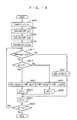
- FIG. 30 shows the flowchart of the rate controlling process performed by the above conventional transcoder 60.
- the rate controlling process performed in the transcoder 60 comprises the steps B1 to B13.
- the steps B6 to B13 are almost the same as those of the steps A7 to A14, respectively, in the rate controlling process shown in Fig. 20 except for the step B7 wherein the utilization volume of the capacity of the virtual buffer is computed on the basis of the target number of outputting bits T out given by the target output bit updating unit 69 instead of the target number of bits T i , T p or T b computed in the step A3 shown in Fig. 20.
- the same steps will be thus omitted from description for avoiding tedious repetition.
- step B1 "1" is assigned to the picture number variable n.
- step B2 the target ratio ioRatio is computed by the above equation (a26).
- step B3 the difference number of bits T diff is computed for the present picture pic(n) by the above equation (a28).
- step B4 then goes forward to the step B4 wherein the number of inputting bits T in is summed up within the first bit streams b 1 .
- the target number of outputting bits T out is computed by the above equation (a27), and further updated by the above equation (a29).
- the inverse quantizer 53 In the second conventional transcoder 60 thus constructed, the inverse quantizer 53, however, cannot start the inverse-quantization process until the target transcoding frame is completely decoded, thereby causing the delay in the transcoding process.
- the third conventional transcoder 80 is also adaptable to perform the rate control without estimating the structure of GROUP OF PICTURES.
- the third conventional transcoder 80 comprises an input terminal a 1 electrically connected to a first transmitting path and designed to input an input bit streams b 3 at the input bit rate, and an output terminal a 2 electrically connected to a second transmitting path and designed to output an output bit streams b 4 at the target bit rate.
- the input bit streams b 3 may have a format, non-adaptable for the MPEG-2, different from that of the bit streams b 1 of the first and second conventional transcoders 50 and 60.
- the input bit streams b 3 have information on the number of coding bits previously recorded thereon by the encoder, not shown.
- the third conventional transcoder 80 comprises a variable length decoder 81 electrically connected to the input terminal a 1 , and a rate controller 82 in addition to the inverse quantizer 53, the quantizer 55, and the variable length encoder 57 which are same as those of the second transcoder 60 shown in FIG. 29.
- the rate controller 82 includes a target output bit updating unit 83, and a quantization parameter computing unit 85 in addition to the target ratio computing unit 63, and the bit difference computing unit 67 which are same as those of the second transcoder 60 shown in FIG. 29.
- the third conventional transcoder 80 thus constructed can perform the rate control on the basis of the formation on the number of coding bits previously recorded in the input bit streams b 3 .
- the variable length decoder 81 is operated to decode the coded moving picture sequence signal within the third bit streams b 3 to reconstruct the pictures and the information on the number of coding bits, and transmit the information to the inverse quantizer 53.
- the variable length decoder 81 is also operated to transmit the number of inputting bits T in to the target output bit updating unit 83.
- the outputting bit updating unit 83 is designed to compute the target number of outputting bits T out on the basis of the number of inputting bits T in and the target ratio ioRatio by the above equation (a26).
- the quantization parameter computing unit 85 is designed to compute the reference quantization parameter Q(j) of the macroblocks MB(j) for each of pictures on the basis of the target number of outputting bits T out updated by the outputting bit updating unit 83 in accordance with the step II in the TM-5.
- the quantizer 55 is then operated to quantize the j -th macroblock MB(j) on the basis of the reference quantization parameter Q(j) given by the quantization parameter computing unit 85.
- FIG. 32 shows the flowchart of the rate controlling process performed by the above third conventional transcoder 80.
- the rate controlling process performed in the transcoder 80 comprises the steps C1 to C13. All the steps C1 to C13 are the same as those of the steps B1 to B13, respectively, in the rate controlling process shown in FIG. 30 except for the step C4 wherein the number of inputting bits T in in the current picture pic(n) is derived from the third bit streams b 3 by the decoder 81 to compute the total number of inputting bits T in .
- the third conventional transcoder 80 thus constructed has information on the number of coding bits previously recorded in the third bit streams b3 thereby making it possible to solve the problem of the delay in the second conventional transcoder 60.
- the third conventional transcoder 80 encounters another problem to restrict the form of the inputted bit streams.
- the encoder which is linked with the third transcoder 80 must provide with the above information on the number of coding bits to be recorded in the bit streams, thereby causing the delay of process in the encoder.
- the matrix of the inverse-quantization coefficients dequant is necessary for only the quantizer 55, but unnecessary for the transcoder itself to generate the desired bit streams.
- a fourth conventional transcoder 90 comprising a level converter 91 instead of the inverse quantizer 53 and the quantizer 55 of the transcoder 50, as shown in FIG. 33.
- the level converter 91 is interposed between the variable length decoder 51 and the variable length encoder 57.
- the level converter 91 is designed to input the original picture data for each of pictures.
- the original picture data includes a matrix of original quantization coefficients level for each of macroblocks within the corresponding picture.
- the level converter 91 is electrically connected to the rate controller 59 and designed to input the second quantization parameter Q 2 from the rate controller 59.
- the level converter 91 is further designed to convert the original picture data for each of pictures including the matrix of original quantization coefficients level into the objective picture data including the matrix of re-quantization coefficients tlevel without generating the matrix of the inverse-quantization coefficients dequant.
- the level converter 91 is thus operable to convert the original picture data, for each of pictures, into the second picture data with the first quantization parameter Q 1 and the second quantization parameter Q 2 .
- the first quantization parameter Q 1 is decoded from the first bit streams b 1 by the variable length decoder 51, while the second quantization parameter Q 2 is obtained from the rate controller 59.
- the rate controller 59 is designed to perform the rate control over the encoding process in the transcoder 90 according to the TM-5.
- the variable length encoder 57 is electrically connected to the level converter 91 and to input the above matrix of re-quantization coefficients tlevel from the level converter 91.
- the fourth conventional transcoder 90 thus constructed can efficiently perform the transcoding process at high speed without storing the matrix of inverse-quantization coefficients dequant in a memory.
- the above conventional transcoders 50, 60, 80 and 90 encounters another problem with the rate-distortion performance in converting the quantization level.
- the rate-distortion performance in converting the quantization level is unstable and variable in accordance with the first and second quantization parameters and the level of the original quantization coefficients level . Therefore, as the amount of reduced information becomes larger, the quantization error is liable to increase, thereby causing the unstable rate control in transcoding.
- the applicant disclosed an apparatus, a method and a computer program product for transcoding a coded moving picture sequence signal, being operable to compute the optimized quantization parameter on the basis of the inverse-quantization parameter and the previously computed quantization parameter in consideration of the characteristics of the rate-distortion performance dependent on the quantization parameter and the inverse-quantization parameter in the patent application No. H11-278867.
- the transcoder disclosed in the aforesaid patent application No. H11-278867 comprising the inverse quantizer for performing the inverse-quantization operation and the quantizer for performing the quantization operation, is characterized in that the transcoder further comprises quantization parameter switching means for switching the quantization parameter in consideration of the characteristics of the rate-distortion performance dependent on the inputted quantization parameter, thereby making it possible for the transcoder to minimize the quantization error occurred when the matrix of original quantization coefficients is transformed to the matrix of re-quantization coefficients.
- the data partitioning is a method of dividing bit streams conveying picture information into two separate bit streams consisting of base layer bit streams indicative of low-frequency DCT coefficients and enhancement layer bit streams indicative of high-frequency DCT coefficients before encoding, and the thus divided base layer bit streams and enhancement layer bit streams are recombined before decoding.
- Original picture information can be roughly decoded and reproduced on the basis of the base layer bit streams indicative of low-frequency DCT coefficients, but not on the basis of the enhancement layer bit streams indicative of high-frequency DCT coefficients alone.
- the high quality of the original picture information can be decoded and reproduced on the basis of the recombination of the base layer bit streams indicative of low-frequency DCT coefficients and the enhancement layer indicative of high-frequency DCT coefficients.
- the SNR scalability is a method of dividing picture signals containing picture information into two separate picture signals consisting of base layer picture signals indicative of low-SNR image and enhancement layer picture signals indicative of high-SNR image before encoding.
- the method of SNR scalability is described in detail.
- the original picture signals have original DCT coefficients.
- the quantizer is operated to roughly quantize base layer bit picture signals indicative of low-SNR image to generate low-SNR bit streams.
- the inverse quantizer is operated to inversely quantize the thus generated low-SNR bit streams to roughly reproduce DCT coefficients. Then, the difference information between the original DCT coefficients and the reproduced DCT coefficients is extracted and quantized to generate the enhancement layer picture signals.
- the enhancement layer picture signals thus generated are used as additional information in combination with the base layer picture signals (low-SNR signals) to reproduce high-SNR signals.
- the above described methods encounter a problem of decreasing the quality of service, i.e., QoS.
- the transcoding process above described is non-reversible.
- the transcoder in general, is operated to decode and inversely quantized DCT coefficients of input bit streams and re-quantize the DCT coefficients thus inversely quantized with re-quantization parameters greater then the original quantization parameters to reduce the amount of bits. This means that the QoS for the input bit streams cannot be reproduced.
- the data partitioning is operated to divide bit streams into two separate bit streams consisting of base layer bit streams indicative of low-frequency DCT coefficients and enhancement layer bit streams indicative of high-frequency DCT coefficients before encoding.
- base layer bit streams indicative of low-frequency DCT coefficients
- enhancement layer bit streams indicative of high-frequency DCT coefficients before encoding.
- the code specifying a boundary between low-frequency coefficients and high-frequency coefficients is defined as "Priority_break_point", which makes it possible for a decoder to distinguish the low-frequency coefficients from the high-frequency coefficients.
- the MP@ML conformable decoder cannot recognize "Priority_break_point”.
- the bit streams indicative of low-frequency coefficients include no EOB code, thereby making it impossible for the MP@ML decoder cannot reproduce the bit streams indicative of low-frequency coefficients.
- the SNR scalability is operated to divide bit streams into two separate bit streams consisting of base layer bit streams indicative of low-SNR signals and enhancement layer bit streams indicative of high-SNR signals before encoding.
- a MP@ML conformable encoder cannot divide bit streams into base layer bit streams indicative of low-SNR signals and enhancement layer bit streams indicative of high-SNR signals and encode the base layer bit streams and enhancement layer bit streams thus divided.
- a MP@MP conformable decoder decode the base layer bit streams and the enhancement layer bit streams. This leads to the fact that an encoder and a decoder dedicated to the SNR scalability are required in place of the MP@ML conformable encoder and decoder.
- the base layer bit streams and the enhancement layer bit streams are required to be processed in parallel, thereby making it complex and difficult to design such SNR scalability conformable encoder and decoder.
- the SNR scalability conformable decoder is operated to receive the base layer bit streams and the enhancement layer bit streams to reproduce and output original picture signals but not in the form of bit streams. This means that the picture signal thus reproduced and outputted must be transcoded again if it is required be in the form of bit streams.
- the present invention is to propose an apparatus, a method and a computer program product for transcoding a first coded moving picture sequence signal to separate into and generate a second coded moving picture sequence signal and a differential coded moving picture sequence signal, which is a difference between the first coded moving picture sequence signal and the second coded moving picture sequence signal, and merging the second coded moving picture sequence signal and the differential coded moving picture sequence signal to reconstruct the first coded moving picture sequence signal.
- the apparatus, method and computer program product thus constructed make it possible for a user to receive transcoded MPEG-2 bit streams at a bit rate lower than that of original MPEG-2 bit streams to reproduce low-quality picture information, and later receive the differential bit streams to reproduce high-quality picture information in combining with the earlier received transcoded MPEG-2 bit streams.
- the apparatus, method and computer program product thus constructed make it possible for a user to decode and transcode MPEG-2 bit streams without any additional devices unlike the aforesaid scalability and data partitioning methods.
- a coded signal separating apparatus for transcoding a first coded moving picture sequence signal to generate a second coded moving picture sequence and a differential coded moving picture sequence signal being a difference between the first coded moving picture sequence signal and the second coded moving picture sequence signal, comprising inputting means for inputting the first coded moving picture sequence signal therethrough, the first coded moving picture sequence signal consisting of a series of first picture information having first coefficient information, and generated as a result of encoding original moving picture sequence signal, the first coefficient information including a matrix of first coefficients; coded signal converting means for inputting the first coded moving picture sequence signal from the inputting means, and converting the first coded moving picture sequence signal inputted through the inputting means to generate the second coded moving picture sequence signal, the second coded moving picture sequence signal consisting of a series of second picture information having second coefficient information, the second coefficient information including a matrix of second coefficients, each of the original moving picture sequence signal, the first coded moving picture sequence signal
- the differential coded signal generating means may be operative to generate the differential coded moving picture sequence signal in the form of the hierarchical structure.
- the second coefficient information includes second zero coefficient information consisting of zero coefficients and second non-zero coefficient information consisting of non-zero coefficients
- the first coefficient information includes zero conversion first coefficient information consisting of zero conversion first coefficients to be converted by the coded signal converting means to the zero coefficients
- non-zero conversion first coefficient information consisting of non-zero conversion first coefficients to be converted by the coded signal converting means to the non-zero coefficients.
- the differential coded signal generating means may include: a coefficient information separating unit for inputting the first coefficient information and the second coefficient information from the coded signal converting means to separate into the zero conversion first coefficient information and the second zero coefficient information from the non-zero conversion first coefficient information and the second non-zero coefficient information, respectively; a zero coefficient encoding unit for inputting the zero conversion first coefficient information from the coefficient information separating unit to extract differential information between the zero conversion first coefficient information and the second zero coefficient information to generate differential zero coefficient information; a non-zero coefficient encoding unit for inputting the non-zero conversion first coefficient information and the second non-zero coefficient information from the coefficient information separating unit to extract differential information between the non-zero conversion first coefficient information and the second non-zero coefficient information to generate differential non-zero coefficient information.
- the non-zero coefficient encoding unit may be operative to generate the differential non-zero coefficient information on the basis of the values of the first coefficients of the non-zero conversion first coefficient information and the values of the second coefficients of the second non-zero coefficient information.
- the coded signal converting means may be operated to obtain a first macroblock quantization parameter used for the quantization of each of the macroblocks contained in the original moving picture sequence signal to generate the macroblocks contained in the first coded moving picture sequence signal from the first coded moving picture sequence signal, and a second macroblock quantization parameter to be used for the inverse-quantization of each of the macroblocks contained in the second coded moving picture sequence signal from the second coded moving picture sequence signal.
- the non-zero coefficient encoding unit may be operative to input the first macroblock quantization parameter and the second macroblock quantization parameter from the coded signal converting means, compute a prediction error between the non-zero conversion first coefficient information and an estimated non-zero conversion first coefficient information on the basis of a ratio of the second macroblock quantization parameter to the first macroblock quantization parameter, and the second non-zero coefficient information.
- the zero coefficient encoding unit may be operative to scan the zero conversion first coefficient information in a zigzag fashion to generate the differential zero coefficient information including combinations of run and level , the run being the number of consecutive zero-value coefficients, the level being the value of a non-zero value coefficient immediately followed by the consecutive zero-value coefficients whereby the zero coefficient encoding unit is operative to eliminate zero coefficients in the zero conversion first coefficient information to compress the amount of information in the differential zero coefficient information.
- the macroblock layer includes blocks consisting of encoded blocks and non-encoded blocks, and a coded block pattern indicating the positions of the respective encoded blocks and non-encoded blocks in the macroblock layer.
- the differential coded signal generating means may be provided with a coded block pattern generating unit operative to generate differential coded block patterns between the coded block patterns of the first coded moving picture sequence signal and the coded block patterns of the second coded moving picture sequence signal.
- the coded block pattern generating unit may be operative to generate differential CBP value strings each indicating the positions of the encoded blocks and non-encoded blocks in the macroblock layer of the first coded moving picture sequence signal with respect to non-encoded blocks of the macroblock layer of the second coded moving picture sequence signal.
- the macroblock layer contains macroblock attribute information including a macroblock address indicating the position of the macroblock, and a macroblock address increment, i.e., MBAI indicating the number of the macroblock addresses to be skipped.
- the differential coded signal generating means may include: a differential macroblock coding unit operative to input macroblocks of the first coded moving picture sequence signal and macroblocks of the second coded moving picture sequence signal from the coded signal converting means to generate macroblocks of the differential coded moving picture sequence signal, the macroblocks of the differential coded moving picture sequence signal being differences between the macroblocks of the first coded moving picture sequence signal and the macroblocks of the second coded moving picture sequence signal with respect to the respective macroblock addresses so as to eliminate macroblocks remained unchanged between the first coded moving picture sequence signal and the second coded moving picture sequence signal with respect to the respective macroblock addresses; and a MBAI coding unit operative to generate the MBAIs of the macroblock attribute information of the differential coded moving picture sequence signal, the MBAIs of the differential coded moving picture sequence signal indicates the number of macroblock addresses of the macroblocks eliminated by the differential macroblock coding unit with respect to the macroblocks of the differential coded moving picture sequence signal generated by the differential macroblock coding unit so that the macro
- the coded signal converting means may be operative to inversely quantize each of the macroblocks contained in the first coded moving picture sequence signal in accordance with the first macroblock quantization parameter to reconstruct the original moving picture sequence signal, and quantize each of the macroblocks of the reconstructed original moving picture sequence signal in accordance with the second macroblock quantization parameter to generate the second coded moving picture sequence signal; and the differential coded signal generating means may include a macroblock quantization parameter reconstruction information generating unit operative to generate macroblock quantization parameter reconstruction information used to reconstruct the first macroblock quantization parameter.
- the coded signal converting means may be operative to convert each of the macroblocks contained in the first coded moving picture sequence signal on the basis of the ratio of the first macroblock quantization parameter to the second macroblock quantization parameter to generate the second coded moving picture sequence signal; and the differential coded signal generating means may include a macroblock quantization parameter reconstruction information generating unit operative to generate macroblock quantization parameter reconstruction information used to reconstruct the first macroblock quantization parameter.
- the macroblock quantization parameter reconstruction information generating unit may be operative to generate the macroblock quantization parameter reconstruction information on the basis of a first quantization parameter derivation constant used to reconstruct the first macroblock quantization parameter from the second macroblock quantization parameter.
- the macroblock quantization parameter reconstruction information generating unit may be operative to generate the macroblock quantization parameter reconstruction information on the basis of a difference between the first quantization parameter derivation constant and previously generated macroblock quantization parameter reconstruction information of the macroblocks of the differential coded moving picture sequence signal.
- the coded signal converting means may be operative to inversely quantize each of the macroblocks contained in the slice layers of the first coded moving picture sequence signal in accordance with a first slice quantization parameter used for the quantization of each of the macroblocks contained in the slice layers of the original moving picture sequence signal to reconstruct the original moving picture sequence signal, and quantize each of the macroblocks in the slice layers of the reconstructed original moving picture sequence signal in accordance with a second slice quantization parameter used for the inverse-quantization of each of the macroblocks contained in the slice layers of the second coded moving picture sequence signal to generate the second coded moving picture sequence signal; and the differential coded signal generating means may include a slice quantization parameter reconstruction information generating unit operative to generate slice quantization parameter reconstruction information used to reconstruct the first slice quantization parameter.
- the coded signal converting means may be operative to convert each of the macroblocks contained in the slice layers of the first coded moving picture sequence signal on the basis of the ratio of the first slice quantization parameter to the second slice quantization parameter to generate the second coded moving picture sequence signal; and the differential coded signal generating means may include a slice quantization parameter reconstruction information generating unit operative to generate slice quantization parameter reconstruction information used to reconstruct the first slice quantization parameter.
- the slice quantization parameter reconstruction information generating unit may be operative to generate the slice quantization parameter reconstruction information on the basis of a first slice quantization parameter derivation constant used to reconstruct the first slice quantization parameter from the second slice quantization parameter.
- the differential coded signal generating means may be provided with a VBV_Delay attaching unit operative to obtain VBV_Delay information indicative of the capacity of VBV buffer from the first coded moving picture sequence signal and attach the VBV_Delay information to the differential coded moving picture sequence signal.
- variable length codes are assigned to the respective differential zero coefficient information and the respective differential non-zero coefficient information in accordance with respective tables
- the differential coded signal generating means may be provided with a variable length code table selecting unit operative to switch the tables in response to the first quantization parameter derivation constants; and a variable-length coding unit operative to assign the differential zero coefficient information and the differential non-zero coefficient information to variable length codes in accordance with the tables switched by the variable length code table selecting unit.
- the differential coded signal generating means may be operative to compute a variable length code to be assigned to the prediction error on the basis of a first quantization parameter derivation constant used to reconstruct the first macroblock quantization parameter from the second macroblock quantization parameter, and the prediction error.
- the differential coded signal generating means may be provided with: a run coding unit operative to assign the runs to variable length codes in accordance with a run table in consideration of the frequency of occurrences; and a level coding unit operative to assign the level s to variable length codes in accordance with a level table in consideration of the frequency of occurrences.
- each of the macroblocks includes the blocks consisting of brightness blocks and color-difference blocks, the differential CBP value strings consisting of differential brightness CBP value strings and differential color-difference CBP value strings, the differential brightness CBP value strings each indicating the positions of the encoded brightness blocks and non-encoded brightness blocks in the respective macroblock layer of the first coded moving picture sequence signal with respect to non-encoded brightness blocks in the respective macroblock layer of the second coded moving picture sequence signal, differential color-difference CBP value strings each indicating the positions of the encoded color-difference blocks and non-encoded color-difference blocks in the respective macroblock layer of the first coded moving picture sequence signal with respect to non-encoded color-difference blocks in the respective macroblock layer of the second coded moving picture sequence signal.
- the coded block pattern generating unit may be further equipped with: an unnecessary block counting section operative to count the number of the unnecessary brightness blocks and the number of the unnecessary color-difference blocks in the macroblock of the second coded moving picture sequence signal; a differential brightness CBP encoding section operative to assign the differential brightness CBP value strings to variable length codes in accordance with a brightness variable length code table; and a differential color-difference CBP encoding section operative to assign the differential color-difference CBP value strings to variable length codes in accordance with a color-difference variable length code table.
- the differential brightness CBP encoding section may be operative to switch the variable length code brightness table in response to the number of the unnecessary brightness blocks counted by the unnecessary block counting section, and the differential color-difference CBP encoding section is operative to switch the color-difference variable length code table in response to the number of the unnecessary differential color-difference blocks counted by the unnecessary block counting section.
- the macroblock quantization parameter reconstruction information generating unit may be operative to compute variable length codes to be assigned to the macroblock quantization parameter reconstruction information in accordance with the absolute value of the macroblock quantization parameter reconstruction information.
- a differential coded signal generating apparatus for inputting a first coded moving picture sequence signal and a second coded moving picture sequence signal to generate a differential coded moving picture sequence signal, the second coded moving picture sequence signal being generated as a result of transcoding the first coded moving picture sequence signal, the differential coded moving picture sequence signal being a difference between the first coded moving picture sequence signal and the second coded moving picture sequence signal, comprising: first coded signal inputting means for inputting the first coded moving picture sequence signal therethrough, the first coded moving picture sequence signal consisting of a series of first picture information having first coefficient information, and generated as a result of encoding original moving picture sequence signal, the first coefficient information including a matrix of first coefficients; second coded signal inputting means for inputting the second coded moving picture sequence signal therethrough, the second coded moving picture sequence signal consisting of a series of second picture information having second coefficient information, the second coefficient information including a matrix of second coefficients; and differential coded signal
- a coded signal merging apparatus for inputting a second coded moving picture sequence signal and a differential coded moving picture sequence signal to reconstruct a first coded moving picture sequence signal, the differential coded moving picture sequence signal being a difference between the first coded moving picture sequence signal and the second coded moving picture sequence signal, comprising: second coded signal inputting means for inputting the second coded moving picture sequence signal therethrough, the second coded moving picture sequence signal consisting of a series of second picture information having second coefficient information, and generated as a result of transcoding the first coded moving picture sequence signal, the second coefficient information including a matrix of second coefficients, the first coded moving picture sequence signal consisting of a series of first picture information having first coefficient information, and generated as a result of encoding original moving picture sequence signal, the first coefficient information including a matrix of first coefficients; differential coded signal inputting means for inputting the differential coded moving picture sequence signal therethrough, the differential coded moving picture sequence including differential coefficient information between the first coefficient
- the second coefficient information may include second zero coefficient information consisting of zero coefficients and second non-zero coefficient information consisting of non-zero coefficients
- the first coefficient information includes zero conversion first coefficient information consisting of zero conversion first coefficients to be converted to the zero coefficients
- non-zero conversion first coefficient information consisting of non-zero conversion first coefficients to be converted to the non-zero coefficients
- the first coded signal merging means may be provided with: a zero conversion first coefficient information generating unit operative to reconstruct the zero conversion first coefficients on the basis of the second zero coefficient information of the second coded moving picture sequence signal and the differential coefficient information of the differential coded moving picture sequence signal; a non-zero conversion first coefficient information generating unit operative to reconstruct the non-zero conversion first coefficients on the basis of the second non-zero coefficient information of the second coded moving picture sequence signal and the differential coefficient information of the differential coded moving picture sequence signal; and a first coefficient information merging unit operative to merge the zero conversion first coefficients information reconstructed by the zero conversion first coefficient information generating unit and non-zero conversion first coefficient information reconstructed by the non-zero conversion first coefficient information generating unit to reconstruct the first coefficient information.
- each of the macroblock layers of the first coded moving picture sequence signal and the second coded moving picture sequence signal includes blocks consisting of encoded blocks and non-encoded blocks, and a coded block pattern indicating the positions of the respective encoded blocks and non-encoded blocks in the macroblock layer
- each of the macroblock layers of differential coded moving picture sequence signal includes a differential coded block pattern being a difference between the coded block patterns of respective macroblock layers of the first coded moving picture sequence signal and the second coded moving picture sequence signal
- the first coefficient information merging unit is provided with a coded block pattern reconstructing section operative to reconstruct the coded block patterns of the macroblock layers of the first coded moving picture sequence signal on the basis of the differential coded block patterns of the differential coded moving picture sequence signal.
- the first coded moving picture sequence signal may include a first macroblock quantization parameter used for the quantization of each of the macroblocks contained in the original moving picture sequence signal
- the second coded moving picture sequence signal includes a second macroblock quantization parameter to be used for the inverse-quantization of each of the macroblocks contained in the second coded moving picture sequence signal
- the first coefficient information merging unit is provided with a macroblock quantization parameter reconstruction information reconstructing section operative to reconstruct the first macroblock quantization parameter reconstruction information used to reconstruct the first macroblock quantization parameter from the differential coded moving picture sequence signal to reconstruct the first macroblock quantization parameter.
- the first coded moving picture sequence signal may include a first slice quantization parameter used for the quantization of each of the macroblocks contained in the slice layer of the original moving picture sequence signal
- the second coded moving picture sequence signal includes a second slice quantization parameter to be used for the inverse-quantization of each of the macroblocks contained in the slice layer of the second coded moving picture sequence signal
- the first coefficient information merging unit is provided with a slice quantization parameter reconstruction information reconstructing section operative to reconstruct the first slice quantization parameter reconstruction information used to reconstruct the first slice quantization parameter from the differential coded moving picture sequence signal to reconstruct the first slice quantization parameter.
- the first coefficient information merging unit may be provided with a VBV_Delay attaching unit operative to obtain VBV_Delay information indicative of the capacity of VBV buffer from the differential coded moving picture sequence signal and attach the VBV_Delay information to the first coded moving picture sequence signal.
- a coded signal separating and merging apparatus comprising: coded signal separating means for transcoding a first coded moving picture sequence signal to generate a second coded moving picture sequence and a differential coded moving picture sequence signal being a difference between the first coded moving picture sequence signal and the second coded moving picture sequence signal; and coded signal merging means for inputting the second coded moving picture sequence signal and the differential coded moving picture sequence signal to reconstruct the first coded moving picture sequence signal.
- the coded signal separating means may include: an inputting unit for inputting the first coded moving picture sequence signal therethrough; a coded signal converting unit for inputting the first coded moving picture sequence signal from the inputting unit, and converting the first coded moving picture sequence signal inputted through the inputting unit to generate the second coded moving picture sequence signal; a differential coded signal generating unit for inputting the first coded moving picture sequence signal and the second coded moving picture sequence signal from the coded signal converting unit to generate the differential coded moving picture sequence signal; a second coded signal outputting unit for outputting the second coded moving picture sequence signal generated by the coded signal converting unit; and a differential coded signal outputting unit for outputting the differential coded moving picture sequence signal generated by the differential coded signal generating unit.
- the coded signal merging means may include: a second coded signal inputting unit for inputting the second coded moving picture sequence signal therethrough; a differential coded signal inputting unit for inputting the differential coded moving picture sequence signal therethrough; a first coded signal merging unit for inputting the second coded moving picture sequence signal from the second coded signal inputting unit and the differential coded moving picture sequence signal from the differential coded signal inputting unit to reconstruct the first coded moving picture sequence signal; and a first coded signal outputting unit for outputting the first coded moving picture sequence signal reconstructed by the first coded signal merging unit.
- a coded signal separating method of transcoding a first coded moving picture sequence signal to generate a second coded moving picture sequence and a differential coded moving picture sequence signal being a difference between the first coded moving picture sequence signal and the second coded moving picture sequence signal comprising the steps of: (a) inputting the first coded moving picture sequence signal therethrough, the first coded moving picture sequence signal consisting of a series of first picture information having first coefficient information, and generated as a result of encoding original moving picture sequence signal, the first coefficient information including a matrix of first coefficients; (b) converting the first coded moving picture sequence signal inputted in the step (a) to generate the second coded moving picture sequence signal, the second coded moving picture sequence signal consisting of a series of second picture information having second coefficient information, the second coefficient information including a matrix of second coefficients, each of the original moving picture sequence signal, the first coded moving picture sequence signal, and the second coded moving picture sequence signal is in the form of a
- the step (c) may have the step of generating the differential coded moving picture sequence signal in the form of the hierarchical structure.
- the second coefficient information includes second zero coefficient information consisting of zero coefficients and second non-zero coefficient information consisting of non-zero coefficients
- the first coefficient information includes zero conversion first coefficient information consisting of zero conversion first coefficients to be converted to the zero coefficients in the step (b)
- non-zero conversion first coefficient information consisting of non-zero conversion first coefficients to be converted to the non-zero coefficients in the step (b).
- the step (c) may further include the steps of: (c1) separating the zero conversion first coefficient information and the second zero coefficient information from the non-zero conversion first coefficient information and the second non-zero coefficient information, respectively; (c2) extracting differential information between the zero conversion first coefficient information and the second zero coefficient information separated in the step (c1) to generate differential zero coefficient information; and (c3) extracting differential information between the non-zero conversion first coefficient information and the second non-zero coefficient information separated in the step (c1) to generate differential non-zero coefficient information.
- the step (c3) may have the step of generating the differential non-zero coefficient information on the basis of the values of the first coefficients of the non-zero conversion first coefficient information and the values of the second coefficients of the second non-zero coefficient information.
- the step (b) may have the step of obtaining a first macroblock quantization parameter used for the quantization of each of the macroblocks contained in the original moving picture sequence signal to generate the macroblocks contained in the first coded moving picture sequence signal from the first coded moving picture sequence signal, and a second macroblock quantization parameter to be used for the inverse-quantization of each of the macroblocks contained in the second coded moving picture sequence signal from the second coded moving picture sequence signal, whereby the step (c3) has the step of computing a prediction error between the non-zero conversion first coefficient information and an estimated non-zero conversion first coefficient information on the basis of a ratio of the second macroblock quantization parameter to the first macroblock quantization parameter, and the second non-zero coefficient information.
- the step (c2) has the step of scanning the zero conversion first coefficient information in a zigzag fashion to generate the differential zero coefficient information including combinations of run and level , the run being the number of consecutive zero-value coefficients, the level being the value of a non-zero value coefficient immediately followed by the consecutive zero-value coefficients whereby the step (c2) has the step of eliminating zero coefficients in the zero conversion first coefficient information to compress the amount of information in the differential zero coefficient information.
- the macroblock layer includes blocks consisting of encoded blocks and non-encoded blocks, and a coded block pattern indicating the positions of the respective encoded blocks and non-encoded blocks in the macroblock layer.
- the step (c) further includes the step of (c4) generating differential coded block patterns between the coded block patterns of the first coded moving picture sequence signal and the coded block patterns of the second coded moving picture sequence signal.
- the step (c4) has the step of generating differential CBP value strings each indicating the positions of the encoded blocks and non-encoded blocks in the macroblock layer of the first coded moving picture sequence signal with respect to non-encoded blocks of the macroblock layer of the second coded moving picture sequence signal.
- the macroblock layer contains macroblock attribute information including a macroblock address indicating the position of the macroblock, and a macroblock address increment, i.e., MBAI indicating the number of the macroblock addresses to be skipped.
- the step (c) further includes the steps of: (c5) generating macroblocks of the differential coded moving picture sequence signal being differences between the macroblocks of the first coded moving picture sequence signal and the macroblocks of the second coded moving picture sequence signal with respect to the respective macroblock addresses so as to eliminate macroblocks remained unchanged between the first coded moving picture sequence signal and the second coded moving picture sequence signal with respect to the respective macroblock addresses; and (c6) generating the MBAI s of the macroblock attribute information of the differential coded moving picture sequence signal, the MBAI s of the differential coded moving picture sequence signal indicates the number of macroblock addresses of the macroblocks eliminated in the step (c5) with respect to the macroblocks of the differential coded moving picture sequence signal generated in the step (c5) so that the macroblocks of the differential coded moving picture sequence signal correspond to the macroblocks of the first coded moving picture sequence signal and the macroblocks of the second coded moving picture sequence signal with respect to the respective macroblock addresses.
- the step (b) has the step of inversely quantizing each of the macroblocks contained in the first coded moving picture sequence signal in accordance with the first macroblock quantization parameter to reconstruct the original moving picture sequence signal, and quantize each of the macroblocks of the reconstructed original moving picture sequence signal in accordance with the second macroblock quantization parameter to generate the second coded moving picture sequence signal.
- the step (c) includes the step of (c7) generating macroblock quantization parameter reconstruction information used to reconstruct the first macroblock quantization parameter.
- the step (b) has the step of converting each of the macroblocks contained in the first coded moving picture sequence signal on the basis of the ratio of the first macroblock quantization parameter to the second macroblock quantization parameter to generate the second coded moving picture sequence signal.
- the step (c) includes the step of (c7) generating macroblock quantization parameter reconstruction information used to reconstruct the first macroblock quantization parameter.
- the step (c7) has the step of generating the macroblock quantization parameter reconstruction information on the basis of a first quantization parameter derivation constant used to reconstruct the first macroblock quantization parameter from the second macroblock quantization parameter.
- the step (c7) has the step of generating the macroblock quantization parameter reconstruction information on the basis of a difference between the first quantization parameter derivation constant and previously generated macroblock quantization parameter reconstruction information of the macroblocks of the differential coded moving picture sequence signal.
- the step (b) has the step of inversely quantizing each of the macroblocks contained in the slice layers of the first coded moving picture sequence signal in accordance with a first slice quantization parameter used for the quantization of each of the macroblocks contained in the slice layers of the original moving picture sequence signal to reconstruct the original moving picture sequence signal, and quantize each of the macroblocks in the slice layers of the reconstructed original moving picture sequence signal in accordance with a second slice quantization parameter used for the inverse-quantization of each of the macroblocks contained in the slice layers of the second coded moving picture sequence signal to generate the second coded moving picture sequence signal; and the step (c) further includes the step of (c8) generating slice quantization parameter reconstruction information used to reconstruct the first slice quantization parameter.
- the step (b) has the step of converting each of the macroblocks contained in the slice layers of the first coded moving picture sequence signal on the basis of the ratio of the first slice quantization parameter to the second slice quantization parameter to generate the second coded moving picture sequence signal; and the step (c) further includes the step of (c8) generating slice quantization parameter reconstruction information used to reconstruct the first slice quantization parameter.
- the step (c8) has the step of generating the slice quantization parameter reconstruction information on the basis of a first slice quantization parameter derivation constant used to reconstruct the first slice quantization parameter from the second slice quantization parameter.
- the step (c) has the step of (c9) obtaining VBV_Delay information indicative of the capacity of VBV buffer from the first coded moving picture sequence signal and attaching the VBV_Delay information to the differential coded moving picture sequence signal.
- variable length codes are assigned to the respective differential zero coefficient information and the respective differential non-zero coefficient information in accordance with respective tables.
- the step (c) further includes the steps of: (c10) switching the tables in response to the first quantization parameter derivation constants; and (c11) assigning the differential zero coefficient information and the differential non-zero coefficient information to variable length codes in accordance with the tables switched in the step (c10).
- the step (c) has the step of computing a variable length code to be assigned to the prediction error on the basis of a first quantization parameter derivation constant used to reconstruct the first macroblock quantization parameter from the second macroblock quantization parameter, and the prediction error.
- the step (c) further includes the steps of: (c12) assigning the runs to variable length codes in accordance with a run table in consideration of the frequency of occurrences; and (c13) assigning the level s to variable length codes in accordance with a level table in consideration of the frequency of occurrences.
- each of the macroblocks includes the blocks consisting of brightness blocks and color-difference blocks, the differential CBP value strings consisting of differential brightness CBP value strings and differential color-difference CBP value strings, the differential brightness CBP value strings each indicating the positions of the encoded brightness blocks and non-encoded brightness blocks in the respective macroblock layer of the first coded moving picture sequence signal with respect to non-encoded brightness blocks in the respective macroblock layer of the second coded moving picture sequence signal, differential color-difference CBP value strings each indicating the positions of the encoded color-difference blocks and non-encoded color-difference blocks in the respective macroblock layer of the first coded moving picture sequence signal with respect to non-encoded color-difference blocks in the respective macroblock layer of the second coded moving picture sequence signal.
- the step (c4) further includes the steps of: (c41) counting the number of the unnecessary brightness blocks and the number of the unnecessary color-difference blocks in the macroblock of the second coded moving picture sequence signal; (c42) assigning the differential brightness CBP value strings to variable length codes in accordance with a brightness variable length code table; and (c43) assigning the differential color-difference CBP value strings to variable length codes in accordance with a color-difference variable length code table, whereby the step (c42) has the step of switching the variable length code brightness table in response to the number of the unnecessary brightness blocks counted in the step (c41), and the step (c43) has the step of switching the color-difference variable length code table in response to the number of the unnecessary differential color-difference blocks counted in the step (c41).
- the step (c7) has the step of computing variable length codes to be assigned to the macroblock quantization parameter reconstruction information in accordance with the absolute value of the macroblock quantization parameter reconstruction information.
- a coded signal merging method of inputting a second coded moving picture sequence signal and a differential coded moving picture sequence signal to reconstruct a first coded moving picture sequence signal, the differential coded moving picture sequence signal being a difference between the first coded moving picture sequence signal and the second coded moving picture sequence signal comprising the steps of: (g) inputting the second coded moving picture sequence signal therethrough, the second coded moving picture sequence signal consisting of a series of second picture information having second coefficient information, and generated as a result of transcoding the first coded moving picture sequence signal, the second coefficient information including a matrix of second coefficients, the first coded moving picture sequence signal consisting of a series of first picture information having first coefficient information, and generated as a result of encoding original moving picture sequence signal, the first coefficient information including a matrix of first coefficients; (h) inputting the differential coded moving picture sequence signal therethrough, the differential coded moving picture sequence including differential coefficient information between the first coefficient information and the second coefficient information,
- the second coefficient information includes second zero coefficient information consisting of zero coefficients and second non-zero coefficient information consisting of non-zero coefficients
- the first coefficient information includes zero conversion first coefficient information consisting of zero conversion first coefficients to be converted to the zero coefficients
- non-zero conversion first coefficient information consisting of non-zero conversion first coefficients to be converted to the non-zero coefficients
- the step (i) further includes the steps of: (i1) reconstructing the zero conversion first coefficients on the basis of the second zero coefficient information of the second coded moving picture sequence signal and the differential coefficient information of the differential coded moving picture sequence signal; (i2) reconstructing the non-zero conversion first coefficients on the basis of the second non-zero coefficient information of the second coded moving picture sequence signal and the differential coefficient information of the differential coded moving picture sequence signal; and (i3) merging the zero conversion first coefficients information reconstructed in the step (i1) and non-zero conversion first coefficient information reconstructed in the step (i2) to reconstruct the first coefficient information.
- each of the macroblock layers of the first coded moving picture sequence signal and the second coded moving picture sequence signal includes blocks consisting of encoded blocks and non-encoded blocks, and a coded block pattern indicating the positions of the respective encoded blocks and non-encoded blocks in the macroblock layer
- each of the macroblock layers of differential coded moving picture sequence signal includes a differential coded block pattern being a difference between the coded block patterns of respective macroblock layers of the first coded moving picture sequence signal and the second coded moving picture sequence signal
- the step (i3) includes the step of (i31) reconstructing the coded block patterns of the macroblock layers of the first coded moving picture sequence signal on the basis of the differential coded block patterns of the differential coded moving picture sequence signal.
- the first coded moving picture sequence signal includes a first macroblock quantization parameter used for the quantization of each of the macroblocks contained in the original moving picture sequence signal
- the second coded moving picture sequence signal includes a second macroblock quantization parameter to be used for the inverse-quantization of each of the macroblocks contained in the second coded moving picture sequence signal
- the step (i3) has the step of (i32) reconstructing the first macroblock quantization parameter reconstruction information used to reconstruct the first macroblock quantization parameter from the differential coded moving picture sequence signal to reconstruct the first macroblock quantization parameter.
- the first coded moving picture sequence signal includes a first slice quantization parameter used for the quantization of each of the macroblocks contained in the slice layer of the original moving picture sequence signal
- the second coded moving picture sequence signal includes a second slice quantization parameter to be used for the inverse-quantization of each of the macroblocks contained in the slice layer of the second coded moving picture sequence signal
- the step (i3) includes the step of (i33) reconstructing the first slice quantization parameter reconstruction information used to reconstruct the first slice quantization parameter from the differential coded moving picture sequence signal to reconstruct the first slice quantization parameter.
- step (i3) includes the step of (i34) obtaining VBV_Delay information indicative of the capacity of VBV buffer from the differential coded moving picture sequence signal and attach the VBV_Delay information to the first coded moving picture sequence signal.
- a coded signal separating and merging method comprising the steps of: (j) transcoding a first coded moving picture sequence signal to generate a second coded moving picture sequence and a differential coded moving picture sequence signal being a difference between the first coded moving picture sequence signal and the second coded moving picture sequence signal; and (k) inputting the second coded moving picture sequence signal and the differential coded moving picture sequence signal to reconstruct the first coded moving picture sequence signal.
- the step (j) further includes the steps of: (j1) inputting the first coded moving picture sequence signal therethrough; (j2) converting the first coded moving picture sequence signal inputted through the step (j1) to generate the second coded moving picture sequence signal; (j3) generating the differential coded moving picture sequence signal from the first coded moving picture sequence signal inputted in the step (j1) and the second coded moving picture sequence signal generated in the step (j2); (j4) outputting the second coded moving picture sequence signal generated in the step (j2); and (j5) outputting the differential coded moving picture sequence signal generated in the step (j3).
- the step (k) includes the steps of: (k1) inputting the second coded moving picture sequence signal therethrough; (k2) inputting the differential coded moving picture sequence signal therethrough; (k3) reconstructing the first coded moving picture sequence signal from the second coded moving picture sequence signal inputted in the step (k1) and the differential coded moving picture sequence signal inputted in the step (k2); and (k4) outputting the first coded moving picture sequence signal reconstructed in the step (k3).
- a computer program product comprising a computer usable storage medium having computer readable code embodied therein for transcoding a first coded moving picture sequence signal to generate a second coded moving picture sequence and a differential coded moving picture sequence signal being a difference between the first coded moving picture sequence signal and the second coded moving picture sequence signal.
- the computer readable code comprising: (a) computer readable program code for inputting the first coded moving picture sequence signal therethrough, the first coded moving picture sequence signal consisting of a series of first picture information having first coefficient information, and generated as a result of encoding original moving picture sequence signal, the first coefficient information including a matrix of first coefficients; (b) computer readable program code for converting the first coded moving picture sequence signal inputted by the computer readable program code (a) to generate the second coded moving picture sequence signal, the second coded moving picture sequence signal consisting of a series of second picture information having second coefficient information, the second coefficient information including a matrix of second coefficients, each of the original moving picture sequence signal, the first coded moving picture sequence signal, and the second coded moving picture sequence signal is in the form of a hierarchical structure including one or more sequence layers each having a plurality of screens sharing common information, one or more picture layers each having a plurality of slices sharing common information with respect to one of the screens, one or more slice layers each having a plurality of macroblock
- the computer readable program code (c) has the computer readable program code for generating the differential coded moving picture sequence signal in the form of the hierarchical structure.
- the second coefficient information includes second zero coefficient information consisting of zero coefficients and second non-zero coefficient information consisting of non-zero coefficients
- the first coefficient information includes zero conversion first coefficient information consisting of zero conversion first coefficients to be converted to the zero coefficients by the computer readable program code (b)
- non-zero conversion first coefficient information consisting of non-zero conversion first coefficients to be converted to the non-zero coefficients by the computer readable program code (b).
- the computer readable program code (c) further includes: (c1) computer readable program code for separating the zero conversion first coefficient information and the second zero coefficient information from the non-zero conversion first coefficient information and the second non-zero coefficient information, respectively; (c2) computer readable program code for extracting differential information between the zero conversion first coefficient information and the second zero coefficient information separated by the computer readable program code (c1) to generate differential zero coefficient information; and (c3) computer readable program code for extracting differential information between the non-zero conversion first coefficient information and the second non-zero coefficient information separated by the computer readable program code (c1) to generate differential non-zero coefficient information.
- the computer readable program code (c3) has the computer readable program code for generating the differential non-zero coefficient information on the basis of the values of the first coefficients of the non-zero conversion first coefficient information and the values of the second coefficients of the second non-zero coefficient information.
- the computer readable program code (b) has the computer readable program code for obtaining a first macroblock quantization parameter used for the quantization of each of the macroblocks contained in the original moving picture sequence signal to generate the macroblocks contained in the first coded moving picture sequence signal from the first coded moving picture sequence signal, and a second macroblock quantization parameter to be used for the inverse-quantization of each of the macroblocks contained in the second coded moving picture sequence signal from the second coded moving picture sequence signal, whereby the computer readable program code (c3) has the computer readable program code for computing a prediction error between the non-zero conversion first coefficient information and an estimated non-zero conversion first coefficient information on the basis of a ratio of the second macroblock quantization parameter to the first macroblock quantization parameter, and the second non-zero coefficient information.
- the computer readable program code (c2) has the computer readable program code for scanning the zero conversion first coefficient information in a zigzag fashion to generate the differential zero coefficient information including combinations of run and level , the run being the number of consecutive zero-value coefficients, the level being the value of a non-zero value coefficient immediately followed by the consecutive zero-value coefficients whereby the computer readable program code (c2) has the computer readable program code for eliminating zero coefficients in the zero conversion first coefficient information to compress the amount of information in the differential zero coefficient information.
- the macroblock layer includes blocks consisting of encoded blocks and non-encoded blocks, and a coded block pattern indicating the positions of the respective encoded blocks and non-encoded blocks in the macroblock layer.
- the computer readable program code (c) further includes (c4) computer readable program code for generating differential coded block patterns between the coded block patterns of the first coded moving picture sequence signal and the coded block patterns of the second coded moving picture sequence signal.
- the computer readable program code (c4) has the computer readable program code for generating differential CBP value strings each indicating the positions of the encoded blocks and non-encoded blocks in the macroblock layer of the first coded moving picture sequence signal with respect to non-encoded blocks of the macroblock layer of the second coded moving picture sequence signal.
- the macroblock layer contains macroblock attribute information including a macroblock address indicating the position of the macroblock, and a macroblock address increment, i.e., MBAI indicating the number of the macroblock addresses to be skipped.
- the computer readable program code (c) further includes: (c5) computer readable program code for generating macroblocks of the differential coded moving picture sequence signal being differences between the macroblocks of the first coded moving picture sequence signal and the macroblocks of the second coded moving picture sequence signal with respect to the respective macroblock addresses so as to eliminate macroblocks remained unchanged between the first coded moving picture sequence signal and the second coded moving picture sequence signal with respect to the respective macroblock addresses; and (c6) computer readable program code for generating the MBAIs of the macroblock attribute information of the differential coded moving picture sequence signal, the MBAIs of the differential coded moving picture sequence signal indicates the number of macroblock addresses of the macroblocks eliminated by the computer readable program code (c5) with respect to the macroblocks of the differential coded moving picture sequence signal
- the computer readable program code (b) has the computer readable program code for inversely quantizing each of the macroblocks contained in the first coded moving picture sequence signal in accordance with the first macroblock quantization parameter to reconstruct the original moving picture sequence signal, and quantize each of the macroblocks of the reconstructed original moving picture sequence signal in accordance with the second macroblock quantization parameter to generate the second coded moving picture sequence signal.
- the computer readable program code (c) includes (c7) computer readable program code for generating macroblock quantization parameter reconstruction information used to reconstruct the first macroblock quantization parameter.
- the computer readable program code (b) has the computer readable program code for converting each of the macroblocks contained in the first coded moving picture sequence signal on the basis of the ratio of the first macroblock quantization parameter to the second macroblock quantization parameter to generate the second coded moving picture sequence signal.
- the computer readable program code (c) includes (c7) computer readable program code for generating macroblock quantization parameter reconstruction information used to reconstruct the first macroblock quantization parameter.
- the computer readable program code (c7) has the computer readable program code for generating the macroblock quantization parameter reconstruction information on the basis of a first quantization parameter derivation constant used to reconstruct the first macroblock quantization parameter from the second macroblock quantization parameter.
- the computer readable program code (c7) has the computer readable program code for generating the macroblock quantization parameter reconstruction information on the basis of a difference between the first quantization parameter derivation constant and previously generated macroblock quantization parameter reconstruction information of the macroblocks of the differential coded moving picture sequence signal.
- the computer readable program code (b) has the computer readable program code for inversely quantizing each of the macroblocks contained in the slice layers of the first coded moving picture sequence signal in accordance with a first slice quantization parameter used for the quantization of each of the macroblocks contained in the slice layers of the original moving picture sequence signal to reconstruct the original moving picture sequence signal, and quantize each of the macroblocks in the slice layers of the reconstructed original moving picture sequence signal in accordance with a second slice quantization parameter used for the inverse-quantization of each of the macroblocks contained in the slice layers of the second coded moving picture sequence signal to generate the second coded moving picture sequence signal.
- the computer readable program code (c) further includes (c8) computer readable program code for generating slice quantization parameter reconstruction information used to reconstruct the first slice quantization parameter.
- the computer readable program code (b) has the computer readable program code for converting each of the macroblocks contained in the slice layers of the first coded moving picture sequence signal on the basis of the ratio of the first slice quantization parameter to the second slice quantization parameter to generate the second coded moving picture sequence signal.
- the computer readable program code (c) further includes (c8) computer readable program code for generating slice quantization parameter reconstruction information used to reconstruct the first slice quantization parameter.
- the computer readable program code (c8) has the computer readable program code for generating the slice quantization parameter reconstruction information on the basis of a first slice quantization parameter derivation constant used to reconstruct the first slice quantization parameter from the second slice quantization parameter.
- the computer readable program code (c) has (c9) computer readable program code for obtaining VBV_Delay information indicative of the capacity of VBV buffer from the first coded moving picture sequence signal and attaching the VBV_Delay information to the differential coded moving picture sequence signal.
- variable length codes are assigned to the respective differential zero coefficient information and the respective differential non-zero coefficient information in accordance with respective tables.
- the computer readable program code (c) further includes: (c10) computer readable program code for switching the tables in response to the first quantization parameter derivation constants; and (c11) computer readable program code for assigning the differential zero coefficient information and the differential non-zero coefficient information to variable length codes in accordance with the tables switched by the computer readable program code (c10).
- the computer readable program code (c) has the computer readable program code for computing a variable length code to be assigned to the prediction error on the basis of a first quantization parameter derivation constant used to reconstruct the first macroblock quantization parameter from the second macroblock quantization parameter, and the prediction error.
- the computer readable program code (c) further includes: (c12) computer readable program code for assigning the runs to variable length codes in accordance with a run table in consideration of the frequency of occurrences; and (c13) computer readable program code for assigning the level s to variable length codes in accordance with a level table in consideration of the frequency of occurrences.
- each of the macroblocks includes the blocks consisting of brightness blocks and color-difference blocks, the differential CBP value strings consisting of differential brightness CBP value strings and differential color-difference CBP value strings, the differential brightness CBP value strings each indicating the positions of the encoded brightness blocks and non-encoded brightness blocks in the respective macroblock layer of the first coded moving picture sequence signal with respect to non-encoded brightness blocks in the respective macroblock layer of the second coded moving picture sequence signal, differential color-difference CBP value strings each indicating the positions of the encoded color-difference blocks and non-encoded color-difference blocks in the respective macroblock layer of the first coded moving picture sequence signal with respect to non-encoded color-difference blocks in the respective macroblock layer of the second coded moving picture sequence signal.
- the computer readable program code (c4) further includes: (c41) computer readable program code for counting the number of the unnecessary brightness blocks and the number of the unnecessary color-difference blocks in the macroblock of the second coded moving picture sequence signal; (c42) computer readable program code for assigning the differential brightness CBP value strings to variable length codes in accordance with a brightness variable length code table; and (c43) computer readable program code for assigning the differential color-difference CBP value strings to variable length codes in accordance with a color-difference variable length code table, whereby the computer readable program code (c42) has the computer readable program code for switching the variable length code brightness table in response to the number of the unnecessary brightness blocks counted by the computer readable program code (c41), and the computer readable program code (c43) has the computer readable program code for switching the color-difference variable length code table in response to the number of the unnecessary differential color-difference blocks counted by the computer readable program code (c41).
- the computer readable program code (c7) has the computer readable program code for computing variable length codes to be assigned to the macroblock quantization parameter reconstruction information in accordance with the absolute value of the macroblock quantization parameter reconstruction information.
- the second coded moving picture sequence signal comprises: (d) computer readable program code for inputting the first coded moving picture sequence signal therethrough, the first coded moving picture sequence signal consisting of a series of first picture information having first coefficient information, and generated as a result of encoding original moving picture sequence signal, the first coefficient information including a matrix of first coefficients; (e) computer readable program code for inputting the second coded moving picture sequence signal therethrough, the second coded moving picture sequence signal consisting of a series of second picture information having second coefficient information, the second coefficient information including a matrix of second coefficients; and (f) computer readable program code for generating the differential coded moving picture sequence signal, whereby the computer readable program code (f) has the computer readable program code for generating the differential coded moving picture sequence signal on the basis of the first coefficient information obtained from the series of first picture information of the first coded moving picture sequence signal, and the second coefficient information obtained from the series of second picture information of the second coded moving picture sequence signal.
- a computer program product comprising a computer usable storage medium having computer readable code embodied therein for inputting a second coded moving picture sequence signal and a differential coded moving picture sequence signal to reconstruct a first coded moving picture sequence signal, the differential coded moving picture sequence signal being a difference between the first coded moving picture sequence signal and the second coded moving picture sequence signal, comprising: (g) computer readable program code for inputting the second coded moving picture sequence signal therethrough, the second coded moving picture sequence signal consisting of a series of second picture information having second coefficient information, and generated as a result of transcoding the first coded moving picture sequence signal, the second coefficient information including a matrix of second coefficients, the first coded moving picture sequence signal consisting of a series of first picture information having first coefficient information, and generated as a result of encoding original moving picture sequence signal, the first coefficient information including a matrix of first coefficients; (h) computer readable program code for inputting the differential coded moving picture sequence signal
- the second coefficient information includes second zero coefficient information consisting of zero coefficients and second non-zero coefficient information consisting of non-zero coefficients
- the first coefficient information includes zero conversion first coefficient information consisting of zero conversion first coefficients to be converted to the zero coefficients
- non-zero conversion first coefficient information consisting of non-zero conversion first coefficients to be converted to the non-zero coefficients
- the computer readable program code (i) further includes: (i1) computer readable program code for reconstructing the zero conversion first coefficients on the basis of the second zero coefficient information of the second coded moving picture sequence signal and the differential coefficient information of the differential coded moving picture sequence signal; (i2) computer readable program code for reconstructing the non-zero conversion first coefficients on the basis of the second non-zero coefficient information of the second coded moving picture sequence signal and the differential coefficient information of the differential coded moving picture sequence signal; and (i3) computer readable program code for merging the zero conversion first coefficients information reconstructed by the computer readable program code (i1) and non-zero conversion first coefficient information reconstructed by the computer readable program code (i2) to reconstruct the first coefficient information.
- each of the macroblock layers of the first coded moving picture sequence signal and the second coded moving picture sequence signal includes blocks consisting of encoded blocks and non-encoded blocks, and a coded block pattern indicating the positions of the respective encoded blocks and non-encoded blocks in the macroblock layer
- each of the macroblock layers of differential coded moving picture sequence signal includes a differential coded block pattern being a difference between the coded block patterns of respective macroblock layers of the first coded moving picture sequence signal and the second coded moving picture sequence signal.
- the computer readable program code (i3) includes (i31) computer readable program code for reconstructing the coded block patterns of the macroblock layers of the first coded moving picture sequence signal on the basis of the differential coded block patterns of the differential coded moving picture sequence signal.
- the first coded moving picture sequence signal includes a first macroblock quantization parameter used for the quantization of each of the macroblocks contained in the original moving picture sequence signal
- the second coded moving picture sequence signal includes a second macroblock quantization parameter to be used for the inverse-quantization of each of the macroblocks contained in the second coded moving picture sequence signal.
- the computer readable program code (i3) has (i32) computer readable program code for reconstructing the first macroblock quantization parameter reconstruction information used to reconstruct the first macroblock quantization parameter from the differential coded moving picture sequence signal to reconstruct the first macroblock quantization parameter.
- the first coded moving picture sequence signal includes a first slice quantization parameter used for the quantization of each of the macroblocks contained in the slice layer of the original moving picture sequence signal
- the second coded moving picture sequence signal includes a second slice quantization parameter to be used for the inverse-quantization of each of the macroblocks contained in the slice layer of the second coded moving picture sequence signal.
- the computer readable program code (i3) includes (i33) computer readable program code for reconstructing the first slice quantization parameter reconstruction information used to reconstruct the first slice quantization parameter from the differential coded moving picture sequence signal to reconstruct the first slice quantization parameter.
- the computer readable program code (i3) includes (i34) computer readable program code for obtaining VBV_Delay information indicative of the capacity of VBV buffer from the differential coded moving picture sequence signal and attach the VBV_Delay information to the first coded moving picture sequence signal.
- a computer program product comprising a computer usable storage medium having computer readable code embodied therein for separating and merging coded signal comprising: (j) computer readable program code for transcoding a first coded moving picture sequence signal to generate a second coded moving picture sequence and a differential coded moving picture sequence signal being a difference between the first coded moving picture sequence signal and the second coded moving picture sequence signal; and (k) computer readable program code for inputting the second coded moving picture sequence signal and the differential coded moving picture sequence signal to reconstruct the first coded moving picture sequence signal.
- the computer readable program code (j) further includes (j1) computer readable program code for inputting the first coded moving picture sequence signal therethrough; (j2) computer readable program code for converting the first coded moving picture sequence signal inputted through the computer readable program code (j1) to generate the second coded moving picture sequence signal; (j3) computer readable program code for generating the differential coded moving picture sequence signal from the first coded moving picture sequence signal inputted by the computer readable program code (j1) and the second coded moving picture sequence signal generated by the computer readable program code (j2); (j4) computer readable program code for outputting the second coded moving picture sequence signal generated by the computer readable program code (j2); and (j5) computer readable program code for outputting the differential coded moving picture sequence signal generated by the computer readable program code (j3).
- the computer readable program code (k) includes (k1) computer readable program code for inputting the second coded moving picture sequence signal therethrough; (k2) computer readable program code for inputting the differential coded moving picture sequence signal therethrough; (k3) computer readable program code for reconstructing the first coded moving picture sequence signal from the second coded moving picture sequence signal inputted by the computer readable program code (k1) and the differential coded moving picture sequence signal inputted by the computer readable program code (k2); and (k4) computer readable program code for outputting the first coded moving picture sequence signal reconstructed by the computer readable program code (k3).
- each of the sequence layers includes a sequence header indicative of the start of the sequence layer
- the differential coded signal generating means includes a sequence header attaching unit operative to attach the sequence headers to the respective sequence layers of the differential coded moving picture sequence signal.
- the differential coded signal generating means includes a bit rate information attaching unit operative to generate first bit rate information indicative of the first bit rate and attach the first bit rate information to the differential coded moving picture sequence signal.
- the bit rate information attaching unit is operative to generate the first bit rate information on the basis of the value of the first bit rate divided by 400 and attach the first bit rate information to the differential coded moving picture sequence signal.
- the first coded moving picture sequence signal is to be transmitted at a first bit rate
- the differential coded moving picture sequence signal includes first bit rate information indicative of the first bit rate
- the first coded signal merging means includes a bit rate information reconstructing unit operative to obtain the first bit rate information from the differential coded moving picture sequence signal to reconstruct the first coded moving picture sequence signal at the first bit rate.
- each of the sequence layers includes a sequence header indicative of the start of the sequence layer.
- the step (c) includes the step of (c14) attaching the sequence headers to the respective sequence layers of the differential coded moving picture sequence signal.
- the step (c) includes the step of (c15) generating first bit rate information indicative of the first bit rate and attaching the first bit rate information to the differential coded moving picture sequence signal.
- the step (c15) has the step of generating the first bit rate information on the basis of the value of the first bit rate divided by 400 and attaching the first bit rate information to the differential coded moving picture sequence signal.
- the first coded moving picture sequence signal is to be transmitted at a first bit rate
- the differential coded moving picture sequence signal includes first bit rate information indicative of the first bit rate
- the step (i) includes the step of (i4) obtaining the first bit rate information from the differential coded moving picture sequence signal to reconstruct the first coded moving picture sequence signal at the first bit rate.
- each of the sequence layers includes a sequence header indicative of the start of the sequence layer.
- the computer readable program code (c) includes (c14) computer readable program code for attaching the sequence headers to the respective sequence layers of the differential coded moving picture sequence signal.
- the first coded moving picture sequence signal is to be transmitted at a first bit rate.
- the computer readable program code (c) includes (c15) computer readable program code for generating first bit rate information indicative of the first bit rate and attaching the first bit rate information to the differential coded moving picture sequence signal.
- the computer readable program code (c15) has the computer readable program code for generating the first bit rate information on the basis of the value of the first bit rate divided by 400 and attaching the first-bit rate information to the differential coded moving picture sequence signal.
- the first coded moving picture sequence signal is to be transmitted at a first bit rate.
- the differential coded moving picture sequence signal includes first bit rate information indicative of the first bit rate.
- the computer readable program code (i) includes (i4) computer readable program code for obtaining the first bit rate information from the differential coded moving picture sequence signal to reconstruct the first coded moving picture sequence signal at the first bit rate.
- FIG. 1 of the drawings there is shown a preferred embodiment of a bit stream separating apparatus 1000 according to the present invention, a preferred embodiment of a bit stream merging apparatus 2000 according to the present invention, an encoder 600, and transmitting paths.
- the encoder 600 is adapted to input original moving picture sequence information, i.e., high-quality moving picture sequence information to output high-quality MPEG-2 bit streams, i.e., original MPEG-2 bit streams.
- the bit stream separating apparatus 1000 is adapted to input the original MPEG-2 bit streams from the encoder 600, and transcode and separate the original MPEG-2 bit streams to generate transcoded MPEG-2 bit streams and differential bit streams.
- the differential bit streams are differences between the original MPEG-2 bit streams and the transcoded MPEG-2 bit streams.
- the transcoded MPEG-2 bit streams and differential bit streams are transmitted through the transmitting paths to users.
- a user may operate a conventional transcoder, not shown, to decode the transcoded MPEG-2 bit streams to reproduce low-quality moving picture sequence information as shown in FIG. 1.
- a user may operate the bit stream merging apparatus 2000 according to present invention to merge the transcoded MPEG-2 bit streams and the differential bit streams to reconstruct the original MPEG-2 bit streams, i.e., high-quality MPEG-2 bit streams, thereby enabling to reproduce the original, high-quality moving picture sequence information.
- the differential bit streams may be transmitted simultaneously with the transcoded MPEG-2 bit streams or may be transmitted after the transcoded MPEG-2 bit streams are transmitted.
- the bit stream separating apparatus 1000 enables to transcode the original MPEG-2 bit stream to separate into and generate the differential bit stream in addition to the transcoded MPEG-2 bit stream.
- the bit stream merging apparatus 2000 according to the present invention enables to reproduce the original, high-quality moving picture sequence information from the transcoded MPEG-2 bit stream and the differential bit stream.
- the bit stream merging apparatus 2000 makes it possible to reproduce the high-quality moving picture sequence information, for instance, from the transcoded MPEG-2 bit stream already received and the differential bit stream just received, thereby eliminating the requirement of transmitting the original MPEG-2 bit streams again through the transmitting path. This leads to the fact that the bit stream separating apparatus 1000 and the bit stream merging apparatus 2000 according to the present invention make it possible to effectively utilize the transcoded MPEG-2 bit streams and the transmitting paths.
- the bit stream separating apparatus 1000 and the bit stream merging apparatus 2000 are, therefore, adapted to prevent the total of the bit rates of the transcoded MPEG-2 bit streams and differential bit streams from exceeding the bit rate of the original MPEG-2 bit streams, which will be described later.
- the bit stream separating apparatus 1000 is shown in FIG. 3 as comprising an inputting terminal a1 connected to an input transmission path, not shown, for inputting the original MPEG-2 bit streams therethrough, a transcoding portion 1100 for inputting the original MPEG-2 bit streams from the inputting terminal a1 and converting the original MPEG-2 bit streams inputted through the inputting terminal a1 to generate the transcoded MPEG-2 bit streams, a differential bit stream generating portion 1200 for inputting the original MPEG-2 bit streams and the transcoded MPEG-2 bit streams from the transcoding portion 1100 to generate the differential bit streams, a first outputting terminal b1 connected to the transcoding portion 1100 for outputting the transcoded MPEG-2 bit stream therethrough to an output transmission path, not shown, and a second outputting terminal b2 connected to the differential bit stream generating portion 1200 for outputting the differential bit streams therethrough to an output transmission path, not shown.
- the bit stream separating apparatus 1000 is adapted to input original MPEG-2 bit streams conformable to MP@ML ("Main Profile Main Level", a form of MPEG-2 coding which covers broadcast television formats up to and including 720 pixels by 576 lines at 30fps using 4:2:0 sampling) to separate into and generate transcoded MPEG-2 bit streams and differential bit streams.
- MP@ML Main Profile Main Level
- the differential bit streams are differences between the original MPEG-2 bit streams and the transcoded MPEG-2 bit streams.
- the MPEG-2 bit streams are in the form of a hierarchical structure.
- the MPEG-2 bit stream includes sequence layers each having a plurality of screens sharing common attribute information such as a picture size, picture layers each having a plurality of slices sharing common picture information such as a picture type with respect to one of the screens, slice layers each having a plurality of macroblocks with respect to one of the slices, macroblock layers each having a plurality of blocks with respect to one of the macroblocks, and block layers each having block information with respect to one of the blocks.
- the sequence layer, the picture layer, the slice layer, the macroblock layer, and the block layer contain sequence layer data elements, picture layer data elements, slice layer data elements, macroblock layer data elements, and block layer data elements, respectively.
- sequence layer contains the sequence layer data elements including a sequence header and the picture layer data elements.
- the picture layer contains picture layer data elements including a picture header and picture data elements.
- Picture data element contains slice layer data elements.
- the slice layer data element contains a slice header and MB layer data elements.
- the MB layer data element contains MB attribute information and block layer data elements.
- the block layer data element contains coefficient information.
- the coefficient information includes a matrix of coefficients.
- the sequence layer, the picture layer, and the slice layer are as a whole referred to as "upper layer”, the macroblock layer, i.e., MB layer is referred to as “middle layer”, and the block layer is referred to as “lower layer”, hereinlater. Furthermore, the information about the upper layer, the middle layer, and the lower layer is referred to as “upper layer information”, “middle layer information”, and “lower layer information, respectively.
- the original MPEG-2 bit streams are generated as a result of encoding original moving picture sequence signal and consist of a series of first picture information having first coefficient information.
- the first coefficient information includes a matrix of first coefficients, which will be described later.
- the transcoded MPEG-2 bit streams, thus transcoded by the transcoding portion 1100, consist of a series of second picture information having second coefficient information.
- the second coefficient information includes a matrix of second coefficients, which will be described later.
- the differential bit stream generating portion 1200 is operative to generate the differential bit streams on the basis of the first coefficient information obtained from the series of first picture information of the original MPEG-2 bit streams, and the second coefficient information obtained from the series of the second picture information of the transcoded MPEG-2 bit streams.
- the differential bit streams are in the form of the hierarchical structure including the sequence layers, the picture layers, the slice layers, the macroblock layers, and the block layers.
- the structure of the MPEG-2 bit stream is shown in FIG. 2.
- the differential bit stream starts from a sequence header of the sequence layer.
- picture layer data elements continue for the number of pictures contained in the sequence layer.
- the picture layer data element comprises a picture header and picture data elements.
- the picture data element includes a plurality of slice layer data elements.
- the slice layer data element comprises a slice header and a plurality of MB layer data elements.
- the MB layer data element comprises MB attribute information and block layer data elements.
- Block layer data element contains coefficient information.
- the coefficient information includes a matrix of coefficients.
- the bit stream separating apparatus 1000 constitutes the coded signal separating apparatus according to the present invention.
- the inputting terminal a1 of the bit stream separating apparatus 1000 constitutes the inputting means according to the present invention.
- the original MPEG-2 bit stream, the transcoded MPEG-2 bit stream, the differential bit stream, and the original moving picture sequence signal constitute the first coded moving picture sequence signal, the second coded moving picture sequence signal, the differential coded moving picture sequence signal, and the original moving picture sequence information according to the present invention, respectively.
- the transcoding portion 1100 constitutes the coded signal converting means according to the present invention.
- the differential bit stream generating portion 1200 constitutes the differential coded signal generating means according to the present invention.
- first coefficient information The coefficient information of the original MPEG-2 bit streams are referred to as "first coefficient information”
- second coefficient information the coefficient information of the transcoded MPEG-2 bit streams
- differential coefficient information the coefficient information of the differential bit streams
- the sequence header, the picture header, and the slice header are used to synchronize output MPEG-2 bit streams in units of the sequence layer, the picture layer, and the slice layer, respectively.
- the MB attribute information is used to indicate the positions of macroblocks, i.e., MBs.
- the coefficient information includes the information about quantization coefficients.
- the values of the coefficients contained in the coefficient information of the MPEG-2 bit streams include zero and non-zero.
- a coefficient whose value equals to zero is referred to as "zero coefficient", and a coefficient whose value is not zero is referred to as "non-zero coefficient", hereinlater.
- the second coefficient information of the transcoded MPEG-2 bit streams includes zero coefficients and non-zero coefficients.
- the second coefficient information is divided into second zero coefficient information consisting of zero coefficients and second non-zero coefficient information consisting of non-zero coefficients.
- Coefficients in the first coefficient information of the original MPEG-2 bit streams are converted by the transcoding portion 1100 to zero coefficients or non-zero coefficients in the second coefficient information of the transcoded MPEG-2 bit streams. Accordingly, coefficients in the first coefficient information to be converted by the transcoding portion 1100 to zero coefficients are referred to as "zero conversion first coefficients" and coefficients in the first coefficient information to be converted by the transcoding portion 1100 to non-zero coefficients are referred to as "non-zero conversion first coefficients".
- the first coefficient information is divided into zero conversion first coefficient information consisting of zero conversion first coefficients and non-zero conversion first coefficient information consisting of non-zero conversion first coefficients.
- the transcoding portion 1100 includes a demultiplexing and decoding unit 1110, a code mode switching unit 1120, a quantization controlling unit 1130, a quantization coefficient converting unit 1140, and a multiplexing and encoding unit 1190.
- the demultiplexing and decoding unit 1110 is adapted to input the original MPEG-2 bit streams from the inputting terminal a1, demultiplex and decode the original MPEG-2 bit streams inputted from the inputting terminal a1 to reconstruct the upper layer information, the middle layer information and the lower layer information, and output the upper layer information and the middle layer information to the code mode switching unit 1120, and the lower layer information to the quantization coefficient converting unit 1140 and the prediction error calculating unit 1230.
- the code mode switching unit 1120 is adapted to input codes contained in the upper layer information and the middle layer information from the demultiplexing and decoding unit 1110 to judge if the codes are to be modified or not with reference to the types of codes.
- the types of codes to be modified are, for instance, codes of MB or CBP, which will be described later. If it is judged that the codes are to be modified, the code mode switching unit 1120 is adapted to modify the codes in accordance with the types of codes and output the upper layer information and the middle layer information including the codes thus modified to the multiplexing and encoding unit 1190 and the differential bit stream generating portion 1200. If it is judged that the codes are not to be modified with reference, the code mode switching unit 1120 is adapted to output the upper layer information and the middle layer information to the multiplexing and encoding unit 1190 and the differential bit stream generating portion 1200.
- the quantization controlling unit 1130 is adapted to output a macroblock re-quantization parameter, i.e., MQ2 with respect to each of macroblocks, i.e., MB to the prediction error calculating unit 1230 and the quantization coefficient converting unit 1140 in order to control the amount of bits.
- MQ2 is used as a macroblock re-quantization parameter to quantize each of the macroblocks contained in the original moving picture sequence information decoded from the original MPEG-2 bit streams to generate macroblocks to be contained in the transcoded MPEG-2 bit streams as well as a macroblock inverse-quantization parameter to inversely quantize each of the macroblocks contained in the transcoded MPEG-2 bit streams to reconstruct the macroblocks of the original moving picture sequence information.
- the quantization coefficient converting unit 1140 is adapted to input QF1 and MQ1 from the demultiplexing and decoding unit 1110, and the re-quantization parameter MQ2 from the quantization controlling unit 1130.
- QF1 is the first coefficient information, i.e., the matrix of coefficients decoded from the original MPEG-2 bit streams
- MQ1 is a macroblock quantization parameter used to quantize each of the macroblocks contained in the original moving picture sequence information to generate the macroblocks to be contained in the original MPEG-2 bit streams as well as a macroblock inverse-quantization parameter used to inversely quantize each of the macroblocks contained in the original MPEG-2 bit streams to reconstruct the macroblocks contained in the original moving picture sequence information.
- the quantization coefficient converter unit 1140 is adapted to inversely quantize the first coefficient information QF1 with the quantization parameter MQ1 and quantize the coefficient information thus inversely quantized with the re-quantization parameter MQ2 to generate second coefficient information, i.e., QF2.
- the quantization coefficient converter unit 1140 is adapted to output the second coefficient information QF2 to the multiplexing and encoding unit 1190, and the first coefficient information QF1 and the second coefficient information QF2 to the differential bit stream generating portion 1200.
- the first coefficient information QF1 and he second coefficient information QF2 are the lower layer information.
- the multiplexing and encoding unit 1190 is adapted to input the upper layer information and the middle layer information from the code mode switching unit 1120 and the lower layer information from the quantization coefficient converter unit 1140, encode and multiplex the upper layer information and the middle layer information inputted from the code mode switching unit 1120 and the lower layer information inputted from the quantization coefficient converter unit 1140 to generate transcoded MPEG-2 bit streams to be outputted to the outputting terminal b1.
- the differential bit stream generating portion 1200 includes a differential coefficient information separating unit 1220, a prediction error computing unit 1230, a differential coefficient information zigzag scanning unit 1240, and a differential BS multiplexing and encoding unit 1290.
- the prediction error computing unit 1230 is adapted to input the non-zero conversion first coefficient information QF1 (QF2 ⁇ 0), the second non-zero coefficient information QF ⁇ 0 from the differential coefficient information separating unit 1220, the macroblock quantization parameter MQ1 from the demultiplexing and decoding unit 1110, and the macroblock re-quantization parameter MQ2 from the quantization controlling unit 1130 to extract differential information between the non-zero conversion first coefficient information QF1 (QF2 ⁇ 0) and the second non-zero coefficient information QF2 ⁇ 0 to generate differential non-zero coefficient information.
- the prediction error computing unit 1230 is adapted to input the non-zero conversion first coefficient information QF1 (QF2 ⁇ 0) and the second non-zero coefficient information QF2 ⁇ 0 from the differential coefficient information separating unit 1220, and the macroblock quantization parameter MQ1 and the macroblock re-quantization parameter MQ2 from the transcoding portion 1100 to compute a prediction error, hereinlater referred to as " ⁇ QF", between the real non-zero conversion first coefficient information QF1 (QF2 ⁇ 0) and an estimated non-zero conversion first coefficient information on the basis of the ratio of the macroblock re-quantization parameter MQ2 to the macroblock quantization parameter MQ1, the values of coefficients of the non-zero conversion first coefficient information QF1 (QF2 ⁇ 0) and the values of the coefficients of the second non-zero coefficient information QF2 ⁇ 0, and output the prediction error ⁇ QF thus computed to the differential BS multiplexing and encoding unit 1290 as lower layer information.
- the estimated non-zero conversion first coefficient information is intended to mean non-zero conversion first coefficient information estimated on the basis of the macroblock re-quantization parameter MQ2 and the macroblock quantization parameter MQ1, and the second non-zero coefficient information QF2 ⁇ 0.
- the differential zero coefficient information includes combinations of run and level.
- the run is the number of consecutive zero-value coefficients
- the level is the value of a non-zero value coefficient immediately followed by the consecutive zero-value coefficient.
- the differential BS multiplexing and encoding unit 1290 is adapted to encode and multiplex the upper layer information and the middle layer information inputted from the code mode switching unit 1120 and the lower layer information inputted from the prediction error computing unit 1230 and the differential coefficient information zigzag scanning unit 1240 to generate the differential bit streams to be outputted to the second outputting terminal b2.
- the differential coefficient information separating unit 1220 constitutes the coefficient information separating unit according to the present invention.
- the prediction error calculating unit 1230 constitutes the non-zero coefficient encoding unit according to the present invention.
- the differential coefficient information zigzag scanning unit 1240 constitutes the zero coefficient encoding unit according to the present invention.
- the bit stream separating apparatus 1000 thus construct is adapted to input the original MPEG-2 bit streams and output the transcoded MPEG-2 bit streams and the differential bit streams.
- the bit stream separating apparatus 1000 is adapted to alternately output codes of the transcoded MPEG-2 bit streams and the differential bit streams in response to codes of the original MPEG-2 bit streams sequentially inputted. This means that the bit stream separating apparatus 1000 is adapted to alternately switch codes to be outputted from the transcoded MPEG-2 bit streams to the differential bit streams and vice versa during the output operation.
- the codes of the differential bit streams to be outputted are sequence headers, picture headers, slice headers, MB data elements, i.e., MB attribute information, and block data elements, i.e., coefficient information as shown in FIG. 4.
- the sequence headers, picture headers, and the slice headers are referred to as "codes of the upper layer information” or "upper layer codes”.
- MB attribute information and coefficient information are referred to as "codes of middle layer information” and “codes of lower layer information”, or “middle layer codes” and “lower layer codes”, respectively.
- the codes of transcoded MPEG-2 bit stream correspond to the codes of the differential bit stream in a one-to-one relationship, thereby making it possible for the bit stream separating apparatus 1000 to alternately output the codes of the transcoded MPEG-2 bit streams and the differential bit streams one code after another as shown in FIG. 4.
- bit stream separating apparatus 1000 is operated to output a sequence header Sequence_Header_Code of the transcoded MPEG-2 bit stream and subsequently output a sequence header Sequence_Header_Code of the differential bit stream.
- bit stream separating apparatus 1000 is operated to output a picture header Picture_Start_Code of the differential bit stream followed by a picture header Picture_Start_Code of the transcoded MPEG-2 bit stream.
- the bit stream separating apparatus 1000 is operated to output a slice header Slice_Start_Code of the transcoded MPEG-2 bit stream and subsequently output a picture header Slice_Start_Code of the differential bit stream.
- the bit stream separating apparatus 1000 is operated to judge if coefficient information is changed between the original MPEG-2 bit stream and the transcoded MPEG-2 bit stream for the corresponding macroblock after the middle layer and lower layer codes of the transcoded MPEG-2 bit stream is outputted, and sequentially output the middle layer codes and lower layer codes of the differential bit stream only when it is judged that the coefficient information is changed between the original MPEG-2 bit stream and the transcoded MPEG-2 bit stream as shown in FIG. 4.
- bit stream separating apparatus 1000 is operated to generate and output differential information about the MB attribute information and coefficient information for the macroblocks for which it is judged that coefficient information is changed between the original and transcoded MPEG-2 bit streams and output the middle and output lower layer codes of the differential bit stream followed by the corresponding middle and lower layer codes of the transcoded MPEG-2 bit stream as shown in FIG. 4.
- the bit stream merging apparatus 2000 is shown in FIG. 5 as comprising a transcoded bit stream inputting terminal a 3 connected to a transmitting path such as network and storage, not shown, for inputting the transcoded MPEG-2 bit streams therethrough, a differential bit stream inputting terminal a4 connected to a transmitting path such as network and storage, not shown, for inputting the differential bit streams therethrough, a BS demultiplexing and decoding unit 2110, a differential BS demultiplexing and decoding unit 2120, a code mode switching unit 2130, a coefficient information reconstructing unit 2140, a differential coefficient information reconstructing unit 2150, an adding unit 2160, a reconstructed coefficient information scanning unit 2170, a multiplexing and encoding unit 2190, and a outputting terminal b3 connected to a transmission path, not shown.
- the BS demultiplexing and decoding unit 2110 is adapted to input the transcoded MPEG-2 bit streams from the transcoded bit stream inputting terminal a3 to demultiplex and decode the upper layer information, the middle layer information, and the lower layer information, and output the upper layer information and the middle layer information thus demultiplexed and decoded to the code mode switching unit 2130 and the lower layer information thus demultiplexed and decoded to the coefficient information reconstructing unit 2140.
- the lower layer information of the transcoded MPEG-2 bit streams includes coefficient information, i.e., combinations of run and level .
- the differential BS demultiplexing and decoding unit 2120 is adapted to input the differential bit streams from the differential bit stream inputting terminal a4 to demultiplex and decode the upper layer information, the middle layer information, and the lower layer information, and output the upper layer information and the middle layer information thus demultiplexed and decoded to the code mode switching unit 2130 and the lower layer information thus demultiplexed and decoded to the coefficient information reconstructing unit 2140 and the differential coefficient information reconstructing unit 2150.
- the lower layer information of the differential bit streams includes coefficient information.
- the coefficient information of the differential bit stream that is, differential coefficient information includes non-zero coefficient information, i.e., prediction error ⁇ QF, and zero coefficient information, i.e., combinations of runs and levels as described hereinbefore.
- the differential BS demultiplexing and decoding unit 2120 is adapted to output the differential non-zero coefficient information, i.e., the prediction error ⁇ QF to the coefficient information reconstructing unit 2140 and the differential zero coefficient information, i.e., the coefficient information run and level to the differential coefficient information reconstructing unit 2150.
- the code mode switching unit 2130 is adapted to input the upper layer information and the middle layer information from the BS demultiplexing and decoding unit 2110 and the differential BS demultiplexing and decoding unit 2120 to reconstruct the upper layer information and the middle layer information of the original MPEG-2 bit stream information, macroblock quantization parameter MQ1, and macroblock re-quantization parameter MQ2, and output the upper layer information and the middle layer information of the original MPEG-2 bit stream information thus reconstructed to the multiplexing and encoding unit 2190 and the macroblock quantization parameter MQ1 and macroblock re-quantization parameter MQ2 thus reconstructed to the coefficient information reconstructing unit 2140.
- the coefficient information reconstructing unit 2140 is adapted to input the lower layer information of the transcoded MPEG-2 bit stream, i.e., combinations of run and level from the BS demultiplexing and decoding unit 2110, the non-zero coefficient information of the differential bit stream, i.e., the prediction error ⁇ QF from the differential BS demultiplexing and decoding unit 2120, and the macroblock quantization parameter MQ1 and macroblock re-quantization parameter MQ2 from the code mode switching unit 2130 to reconstruct differential non-zero coefficient information, i.e., 8 by 8 matrices of coefficients and output the 8 by 8 matrices of coefficients thus reconstructed to the adding unit 2160.
- the differential coefficient information reconstructing unit 2150 is adapted to input the differential zero coefficient information, i.e., the coefficient information run and level from the differential BS demultiplexing and decoding unit 2120 to reconstruct differential zero coefficient information, i.e., 8 by 8 matrices of coefficients and output the 8 by 8 matrices of coefficients thus reconstructed to the adding unit 2160.
- the adding unit 2160 is adapted to input the differential non-zero coefficient information, i.e., 8 by 8 matrices of coefficients from the coefficient information reconstructing unit 2140 and the differential zero coefficient information, i.e., 8 by 8 matrices of coefficients from the differential coefficient information reconstructing unit 2150 and add the differential non-zero coefficient information, i.e., 8 by 8 matrices of coefficients to the differential zero coefficient information, i.e., 8 by 8 matrices of coefficients to reconstruct the 8 by 8 matrices of first coefficients of the original MPEG-2 bit streams and output the 8 by 8 matrices of the first coefficients of the original MPEG-2 bit streams thus reconstructed to the reconstructed coefficient information scanning unit 2170.
- the reconstructed coefficient information scanning unit 2170 is adapted to input the reconstructed 8 by 8 matrices from the adding unit 2160 to scan run s and level s in a zigzag fashion to reconstruct one-dimensional combination of run s and level s, i.e., the first coefficient information, and output the first coefficient information, i.e., the lower layer information thus reconstructed to the multiplexing and encoding unit 2190.
- the multiplexing and encoding unit 2190 is adapted to input the upper layer information and the middle layer information from the code mode switching unit 2130, and lower layer information from the reconstructed coefficient information scanning unit 2170, multiplex and encode the upper layer information, middle layer information, and the lower layer information to reconstruct the original MPEG-2 bit stream, and output the original MPEG-2 bit stream thus reconstructed to the outputting terminal b3.
- the bit stream merging apparatus 2000 thus constructed is adapted to input and merge the transcoded MPEG-2 bit streams and the differential bit streams to reconstruct the original MPEG-2 bit streams.
- the bit stream merging apparatus 2000 constitutes the coded signal merging apparatus according to the present invention.
- the transcoded bit stream inputting terminal a3 and the differential bit stream inputting terminal a4 constitute the second coded signal inputting means and the differential coded signal inputting means according to the present invention, respectively.
- the BS demultiplexing and decoding unit 2110, the differential BS demultiplexing and decoding unit 2120, the code mode switching unit 2130, the coefficient information reconstructing unit 2140, the differential coefficient information reconstructing unit 2150, the adding unit 2160, the reconstructed coefficient information scanning unit 2170, and the multiplexing and encoding unit 2190 collectively constitute the first coded signal merging means according to the present invention.
- the coefficient information reconstructing unit 2140 constitutes the non-zero conversion first coefficient information generating unit according to the present invention.
- the combinations of run and level from the BS demultiplexing and decoding unit 2110 and the prediction error ⁇ QF from the differential BS demultiplexing and decoding unit 2120 constitute the second non-zero coefficient information of the second coded moving picture sequence signal and the differential coefficient information of the differential coded moving picture sequence signal, respectively.
- the differential coefficient information reconstructing unit 2150 and the adding unit 2160 collectively constitute the zero conversion first coefficient information generating unit according to the present invention.
- the combinations of run and level from the BS demultiplexing and decoding unit 2110 received through the coefficient information reconstructing unit 2140 and the coefficient information run and level from the differential BS demultiplexing and decoding unit 2120 constitutes the second zero coefficient information of the second coded moving picture sequence signal and the differential coefficient information of the differential coded moving picture sequence signal, respectively.
- the adding unit 2160 and the reconstructed coefficient information scanning unit 2170 collectively constitute the first coefficient information merging unit according to the present invention.
- the bit stream merging apparatus 2000 thus constructed can input the transcoded MPEG-2 bit streams and the differential bit streams to reconstruct the original MPEG-2 bit streams.
- the bit stream merging apparatus 2000 thus constructed is adapted to input the transcoded MPEG-2 bit streams and the differential bit streams to reconstruct the original MPEG-2 bit streams.
- the bit stream merging apparatus 2000 is adapted to alternately input codes of the transcoded MPEG-2 bit streams and the differential bit streams. This means that the bit stream merging apparatus 2000 is adapted to alternately input the codes of the transcoded MPEG-2 bit streams and the differential bit streams. This means that the bit stream merging apparatus 2000 is adapted to alternately switch codes to be inputted from the transcoded MPEG-2 bit streams to the differential bit streams and vice versa during the input operation.
- the codes of transcoded MPEG-2 bit stream correspond to the codes of the differential bit stream in a one-to-one relationship, thereby making it possible for the bit stream merging apparatus 2000 to alternately input the codes of the transcoded MPEG-2 bit streams and the differential bit streams one code after another code.
- the bit stream merging apparatus 2000 is operated to judge if MB attribute information and coefficient information are provided in the macroblock of the differential bit stream every time when the MB attribute information and coefficient information in one macroblock of the transcoded MPEG-2 bit stream is read.
- the bit stream merging apparatus 2000 is operated to input the MB attribute information and coefficient information in the macroblock of the differential bit stream followed by the corresponding MB attribute information and coefficient information of the transcoded MPEG-2 bit stream in the macroblocks for which if it is judged that MB attribute information and coefficient information are provided in the macroblock of the differential bit stream.
- differential bit stream generating portion 1200 of the bit stream separating apparatus 1000 may be constructed separately from the transcoding portion 1100 of the bit stream separating apparatus 1000.
- the differential bit stream generating portion 1200 may be provided with an original MPEG-2 bit stream inputting means and a transcoded MPEG-2 bit stream inputting means, not shown.
- the original MPEG-2 bit stream inputting means may be operative to input the original MPEG-2 bit stream therethrough.
- the transcoded MPEG-2 bit stream inputting means is operative to input the transcoded MPEG-2 bit stream therethrough.
- the original MPEG-2 bit stream inputting means constitutes the first coded signal inputting means according to the present invention
- the transcoded MPEG-2 bit stream inputting means constitutes the second coded signal inputting means according to the present invention.
- bit stream separating apparatus 1000 and bit stream merging apparatus 2000 may be integrated to a single apparatus which enables to separate and merge the MPEG-2 bit stream.
- bit stream separating apparatus 1000 The major constructions and functions of the bit stream separating apparatus 1000 and the bit stream merging apparatus 2000 according to the present invention have thus far been described.
- the differential bit stream in the form of the hierarchical structure including the sequence layers, the picture layers, the slice layers, the macroblock layers, and the block layers.
- the upper layer codes of the differential bit stream include the sequence header, the picture header, and the slice headers, as described hereinbefore.
- sequence header of the differential bit stream contains "Sequence Header Code (Sequence_Header_Code )”.
- Sequence Header Code is defined as a unique code of 32 bit length and used to synchronize bit streams per each of sequence layers.
- the bit stream separating apparatus 1000 is operated to alternately output Sequence Start Codes of the transcoded MPEG-2 bit stream and the differential bit stream one code after another to synchronize the transcoded MPEG-2 bit stream and the differential bit stream.
- the bit stream merging apparatus 2000 is operated to alternately input Sequence Header Code of the transcoded MPEG-2 bit stream and only read the differential bit stream to synchronize the transcoded MPEG-2 bit stream and the differential bit stream.
- the sequence header of the differential bit stream may contain "Sequence Start Code (Sequence_Start_Code )”, and "Original Bit Rate Value (Original_Bit_Rate Value)”.
- Sequence Start Code is defined as a defined as a unique code of 32 bit length and used to synchronize the differential bit stream and the transcoded MPEG-2 bit stream per each of sequence layers. Sequence Start Code can be searched in the MPEG-2 bit stream to detect the start of the sequence layer.
- Original Bit Rate Value is defined as 18 bit length code and used to indicate the value of the bit rate of the original MPEG-2 bit stream divided by 400.
- Each of the original MPEG-2 bit stream and the transcoded MPEG-2 bit stream contains Sequence Start Code and Bit Rate Value in place of Original Bit Rate Value.
- Bit Rate Value of the original MPEG-2 bit stream or the transcoded MPEG-2 bit stream indicates the bit rate value of the original MPEG-2 bit stream or the transcoded MPEG-2 bit stream.
- the differential BS multiplexing and encoding unit 1290 of the bit stream separating apparatus 1000 has a sequence header attaching unit, not shown, to generate and attach the sequence headers, i.e., Sequence Start Codes or Sequence Start Codes to the respective sequence layers of the differential bit stream.
- the differential BS multiplexing and encoding unit 1290 of the bit stream separating apparatus 1000 has a bit rate information attaching unit, not shown, to generate first bit rate information, i.e., Original Bit Rate Value on the basis of the value of the bit rate divided by 400 and attach the first bit rate information to the respective sequence layers of the differential bit stream.
- first bit rate information i.e., Original Bit Rate Value
- the multiplexing and encoding unit 2190 of the bit stream merging apparatus 2000 has a bit rate information reconstructing unit, not shown, to obtain the first bit rate information i.e., Original Bit Rate Value from the sequence layer of the differential bit stream to reconstruct the original MPEG-2 bit stream at the bit rate indicated by the first bit rate information.
- the first bit rate information i.e., Original Bit Rate Value
- the bit stream separating apparatus 1000 is operated to alternately output Sequence Start Code and Bit Rate Value of the transcoded MPEG-2 bit stream and Sequence Start Code and Original Bit Rate Value of the differential bit stream to synchronize transcoded MPEG-2 bit stream and differential bit stream.
- the bit stream merging apparatus 2000 is operated to alternately input Sequence Start Code and Bit Rate Value of the transcoded MPEG-2 bit stream and read Sequence Start Code and Original Bit Rate Value of the differential bit stream to synchronize the transcoded MPEG-2 bit stream and the differential bit stream.
- the multiplexing and encoding unit 2190 of the bit stream merging apparatus 2000 is operated to replace Bit Rate Value of the transcoded MPEG-2 bit stream with Original Bit Rate Value of the differential bit stream upon reading Original Bit Rate Value of the differential bit stream so as to precisely reconstruct the sequence header of the original MPEG-2 bit stream.
- the picture header of the differential bit stream contains "Picture Start Code ( Picture_Start_Code )", “Temporal Reference ( Temporal_Reference )”, “Picture Coding Type ( Picture_Coding_Type )”, and "VBV Delay ( VBV_Delay )”.
- Picture Start Code is defined as 32 bit length code and used to synchronize bit streams per each of picture layers.
- Temporal Reference hereinlater referred to as "TR”
- 10 bit length code is defined as 10 bit length code and used to indicate the sequence of picture in the GOP layer.
- Picture Coding Type hereinlater referred to as "PCT” is defined as 2 bit length code and used to indicate the type of picture.
- VBV Delay is defined as 16 bit length code and used to indicate the capacity of VBV buffer, i.e., Video Buffering Verifier in units of 90 kHz clock.
- TR and PCT remain unchanged between the original MPEG-2 bit stream and the transcoded MPEG-2 bit stream.
- TR and PCT can be used to synchronize MPEG-2 bit streams in addition to Picture Start Code per each of picture layers.
- VBV Delay of the transcoded MPEG-2 bit stream is different from the value of the VBV Delay of the original MPEG-2 bit stream since the bit rate changes between the original MPEG-2 bit stream and the transcoded MPEG-2 bit stream.
- VBV Delay of the transcoded MPEG-2 bit stream is hereinlater referred to as "Vbv Delay (Vbv_Delay)".
- Vbv Delay Vbv_Delay
- the value of VBV Delay of the original MPEG-2 bit stream is written in VBV Delay of the differential bit stream.
- VBV Delay of the differential bit stream is same as that of VBV Delay of the original MPEG-2 bit stream.
- the differential BS multiplexing and encoding unit 1290 of the differential bit stream generating portion 1200 is provided with a picture header attaching unit, not shown, to obtain TR, PCT, and VBV_Delay of the original MPEG-2 bit stream from the code mode switching unit 1120, and sequentially attach Picture Start Code, TR, PCT, and VBV_Delay to the picture layer of the differential bit stream.
- differential BS multiplexing and encoding unit 1290 is operative to obtain VBV_Delay information indicative of the capacity of VBV buffer from the transcoding portion 1100 and attach the VBV_Delay information to the differential bit stream, which will be described later.
- the differential BS multiplexing and encoding unit 1290 constitutes the VBV_Delay attaching unit according to the present invention.
- the code mode switching unit 2130 and the multiplexing and encoding unit 2190 of the bit stream merging apparatus 2000 are operated to obtain VBV Delay indicative of the capacity of VBV buffer from the differential bit stream to replace Vbv Delay of the transcoded MPEG-2 bit stream with VBV Delay of the differential bit stream so as to reconstruct VBV Delay of the original MPEG-2 bit stream.
- the code mode switching unit 2130 and the multiplexing and encoding unit 2190 of the bit stream merging apparatus 2000 collectively constitute the VBV_Delay attaching unit according to the present invention.
- the slice header of the differential bit stream contains "Slice Start Code (Slice_Start_Code)" and "Slice MQm Value (Slice_MQm_Value)”.
- Slice Start Code is defined as a unique code of 32 bit length and used to synchronize bit streams per each of slice layers.
- Slice MQm Value is defined as a slice quantization parameter reconstruction code, i.e., slice quantization parameter reconstruction information of 1 to 31 bit length.
- the bit stream separating apparatus 1000 and the bit stream merging apparatus 2000 according to the present invention are operated to prevent the total of the bit rates of the transcoded MPEG-2 bit streams and the differential bit stream from exceeding the bit rate of the original MPEG-2 bit streams by setting quantization parameter prohibition areas.
- the operation of preventing the total bit rate of the transcoded MPEG-2 bit streams and the differential bit streams from exceeding the bit rate of the original MPEG-2 bit streams by setting quantization parameter prohibition areas is hereinlater referred to as "the control operation by means of setting quantization parameter prohibition areas”.
- the slice quantization parameter used to inversely quantize the original MPEG-2 bit stream is referred to as "SMQ1".
- the slice quantization parameter used for re-quantization to generate the transcoded MPEG-2 bit stream is referred to as "SMQ2".
- the control operation by means of setting quantization parameter prohibition areas is performed by limiting the slice re-quantization parameters SMQ2. More specifically, a transcoder computes a slice re-quantization parameter, referred to as "SMQ2*" in accordance with the quantization characteristic inherent to the transcoder. The control operation is performed by updating SMQ2* in a fashion described hereinlater to generate slice re-quantization parameter SMQ2 in order to limit the slice re-quantization parameter.
- the slice re-quantization parameter SMQ2 is computed by updating SMQ2* in accordance with a slice re-quantization parameter derivation constant, hereinlater referred to as "sm". "sm" is an integer.
- the slice re-quantization parameter derivation constant sm can be used to reconstruct the slice quantization parameter SMQ1.
- the slice re-quantization parameter derivation constant sm is also referred to as "slice quantization parameter derivation constant", which will be described later.
- the transcoding portion 1100 of the bit stream separating apparatus 1000 is operative to inversely quantize each of the macroblocks contained in the slice layers of the original MPEG-2 bit stream in accordance with a slice quantization parameter SMQ1 used for the quantization of each of the macroblocks contained in the slice layers of the original moving picture sequence information to reconstruct the original moving picture sequence signal, and quantize each of the macroblocks in the slice layers of the reconstructed original moving picture sequence signal in accordance with a slice layer re-quantization parameter SMQ2 used for the inverse-quantization of each of the macroblocks contained in the slice layers of the transcoded MPEG-2 bit stream to generate the transcoded MPEG-2 bit stream.
- a slice quantization parameter SMQ1 used for the quantization of each of the macroblocks contained in the slice layers of the original moving picture sequence information to reconstruct the original moving picture sequence signal
- SMQ2 used for the inverse-quantization of each of the macroblocks contained in the slice layers of the transcoded MPEG-2 bit stream to generate
- the differential bit stream generating portion 1200 of the bit stream separating apparatus 1000 includes a slice quantization parameter reconstruction information generating unit operative to generate slice quantization parameter reconstruction information Slice MQm Value used to reconstruct slice quantization parameter SMQ1.
- the prediction error calculating unit 1230 and the differential BS multiplexing and encoding unit 1290 of the differential bit stream generating portion 1200 collectively constitute the slice quantization parameter reconstruction information generating unit according to the present invention.
- the differential bit stream generating portion 1200 is operative to generate the slice quantization parameter reconstruction information sm in accordance with Equations (1) and (2) as follows:
- the slice re-quantization parameter SMQ2 is computed by using the slice quantization parameter SMQ1 and the slice quantization parameter derivation constant sm by Equations (3) and (4) as follows:
- the bit stream separating apparatus 1000 is operated to compute the slice quantization parameter derivation constant sm on the basis of SMQ1, SMQ2* in accordance with Equations (1) and (2), write the slice quantization parameter derivation constant sm into Slice MQm Value, and encode and output Slice MQm Value followed by Slice Start Code.
- the slice re-quantization parameter derivation constant sm is accordingly assigned to the slice quantization parameter reconstruction code, Slice MQm Value to be used to reconstruct the slice quantization parameter SMQ1.
- the slice re-quantization parameter derivation constant sm is to be used to reconstruct the slice quantization parameter SMQ1 from the slice re-quantization parameter SMQ2, and is, therefore, referred to as slice quantization parameter derivation constant, hereinlater.
- the differential bit stream generating portion 1200 of the bit stream separating apparatus 1000 is operative to generate the slice quantization parameter reconstruction information Slice MQm Value on the basis of the slice quantization parameter derivation constant sm used to reconstruct the slice quantization parameter SMQ1 from the slice re-quantization parameter SMQ2.
- the slice quantization parameter derivation constant sm will be also used as an initial value of m_prev used to update a macroblock quantization parameter in each of macroblocks in the respective slice layer during the encoding operation, which will be described later.
- the code mode switching unit 2130, the coefficient information reconstructing unit 2140, the differential coefficient information reconstructing unit 2150, the adding unit 2160, and the reconstructed coefficient information scanning unit 2170 of the bit stream merging apparatus 2000 collectively constitute a slice macroblock quantization parameter reconstruction information reconstructing section, not shown.
- the slice macroblock quantization parameter reconstruction information reconstructing section is operative to reconstruct the slice quantization parameter reconstruction information, the first macroblock quantization parameter reconstruction information, sm used to reconstruct the slice quantization parameter (SMQ1) from the differential bit stream to reconstruct the slice quantization parameter (SMQ1).
- the code mode switching unit 2130, the coefficient information reconstructing unit 2140, the differential coefficient information reconstructing unit 2150, the adding unit 2160, and the reconstructed coefficient information scanning unit 2170 of the bit stream merging apparatus 2000 collectively constitute the slice quantization parameter reconstruction information reconstructing section according to the present invention.
- the bit stream merging apparatus 2000 is operated to decode Slice MQm Value followed by Slice Start Code to obtain the slice quantization parameter derivation constant sm.
- the bit stream merging apparatus 2000 is also operated to obtain SMQ2 from the transcoded MPEG-2 bit stream.
- the bit stream merging apparatus 2000 is then operated to compute SMQ1 on the basis of sm and SMQ2 in accordance with Equation (5) and (6) as follows:
- the slice quantization parameter derivation constant sm will be also used as an initial value of m_prev used to update a macroblock quantization parameter in each of macroblocks in the respective slice layer during the decoding operation, which will be described later.
- the macroblock layer of the MPEG-2 bit streams contains macroblock attribute information including a macroblock address indicating the position of the macroblock, a macroblock address increment, i.e., MBAI indicating the number of the macroblock addresses to be skipped, and a coded block pattern indicating the positions of encoded blocks and non-encoded blocks in the macroblock layer, which will be described hereinlater.
- macroblock attribute information including a macroblock address indicating the position of the macroblock, a macroblock address increment, i.e., MBAI indicating the number of the macroblock addresses to be skipped, and a coded block pattern indicating the positions of encoded blocks and non-encoded blocks in the macroblock layer, which will be described hereinlater.
- the macroblock address i.e., MB address of a macroblock is defined as a MB position index in the horizontal direction, starting from “0" up to "MBLength-1".
- “MBLength” is intended to mean the number of macroblocks aligned for one line.
- FIG. 7 shows MB addresses of picture information with spatial resolution of 704 [pel] x 480 [lines].
- the macroblock layer of the differential bit stream includes macroblock attribute information, i.e., MB attribute information containing a macroblock address increment, i.e., MBAI indicating the number of the macroblock addresses to be skipped, macroblock quantization parameter reconstruction information, i.e., MB quantization parameter reconstructing codes (MQ ⁇ m Value) used to reconstruct macroblock quantization parameters, differential CBP value strings (CBP_y, CBP_uv), which are differential coded block patterns between the coded block patterns of the original MPEG-2 bit stream and the transcoded MPEG-2 bit stream.
- the MBAI contained in the macroblock layer of the differential bit stream is referred to as "differential MBAI”.
- the macroblock contained in the differential bit stream is referred to as "differential macroblock”.
- the differential bit stream generating portion 1200 of the bit stream separating apparatus 1000 is operated to input macroblocks of the original MPEG-2 bit stream and the transcoded MPEG-2 bit stream from the transcoding portion 1100 to generate macroblocks of the differential bit stream, which are the differences between the macroblocks of the original MPEG-2 bit stream and the transcoded MPEG-2 bit stream with respect to the respective macroblock addresses as shown in FIG. 4.
- This means that the differential bit stream generating portion 1200 is operated to generate the differential macroblocks of the differential bit stream with respect to the macroblock addresses so as to eliminate macroblocks remained unchanged between the original MPEG-2 bit stream and the transcoded MPEG-2 bit stream with respect to the respective macroblock addresses.
- the differential coefficient information separating unit 1220, the prediction error computing unit 1230, the differential coefficient information zigzag scanning unit 1240, and the differential BS multiplexing and encoding unit 1290 of the differential bit stream generating portion 1200 collectively constitute the differential macroblock coding unit according to the present invention.
- the differential BS multiplexing and encoding unit 1290 of the bit stream separating apparatus 1000 is provided with a MBAI coding unit, not shown.
- the MBAI coding unit is adapted to generate the MBAI of the macroblock attribute information of the differential bit stream.
- MBAI indicates the number of the macroblock addresses eliminated by the differential bit stream generating portion 1200 with respect to the macroblocks of the differential bit streams generated by the differential bit stream generating portion 1200 so that the macroblocks of the differential bit stream correspond to the macroblocks of the original MPEG-2 bit stream and the macroblocks of the transcoded MEPG-2 bit stream with respect to the respective macroblock addresses.
- the macroblock address increment MBAI of the differential bit stream will be described in detail.
- the differential bit stream is generated as a result of encoding differences between the original MPEG-2 bit stream and the transcoded MPEG-2 bit stream.
- macroblocks whose coefficient information remains unchanged after the re-quantization operation. Furthermore, macroblocks consisting of only zero coefficients remains unchanged after the re-quantization operation. Those macroblocks do not contain any significant information and are accordingly intended to be skipped. More specifically, not all of the macroblocks of the transcoded MPEG-2 bit stream contain significant information to be encoded for the differential bit stream.
- the differential bit stream generating portion 1200 is therefore operated to generate the differential macroblocks of the differential bit stream for the macroblocks whose coefficient information changed after the re-quantization operation with respect to the macroblock addresses so as to eliminate macroblocks remained unchanged between the original MPEG-2 bit stream and the transcoded MPEG-2 bit stream with respect to the respective macroblock addresses.
- the macroblock address increment MBAI of the differential bit stream indicates the position of a macroblock of the differential bit stream as a difference between the address of macroblock previously encoded and the address of the concerned macroblock.
- the process of computing and encoding the macroblock address increment MBAIs in a slice layer performed by the bit stream separating apparatus 1000 will be described in reference to the flowchart of FIG. 8.
- the process of encoding and decoding the macroblock address increment MBAI is referred to as "MB address control”.
- the address of the concerned macroblock is referred to as "MBAddress”
- the address of the macroblock previously encoded is referred to as "MBAddress*prev”.
- step S102 MBAddress*prev is initialized to -1.
- the step S102 goes forward to the step S103 in which a macroblock in the slice layer of the transcoded MPEG-2 bit stream is encoded.
- the step S103 goes forward to the step S104 in which it is judged whether the quantization parameter of the macroblock of the transcoded MPEG-2 bit stream just generated is changed from the quantization parameter of the corresponding macroblock of the slice layer of the original MPEG-2 bit stream. If it is judged that the quantization parameter is not changed, the step S104 goes forward to the step S121.
- the step S112 goes forward to the step S113 in which MBAI is encoded to a variable length code in accordance with a variable length code table, which will be described later.
- the step S113 goes forward to the step S114 in which MBAddress*prev is updated by assigning MBAddress to MBAddress*prev.
- the step S114 goes forward to the step S115 in which all the codes of the differential macroblock are encoded.
- the step S115 goes forward to the step S121 in which it is judged whether the slice layer ends, that is, it is judged whether all the macroblocks of the slice layer of the transcoded MPEG-2 bit stream have been processed. If it is judged that all the macroblocks of the slice layer of the transcoded MPEG-2 bit stream have not yet been processed, the step S121 goes forward to the step S103. Otherwise, the step S121 goes forward to the step END.
- the macroblocks of the differential bit stream do not correspond to the macroblocks of the transcoded MPEG-2 bit stream in a one-to-one relationship.
- the MB addresses of the differential bit stream do not correspond to those of the transcoded MPEG-2 bit stream.
- the MBAI s of the differential bit stream are independent of MBAI s of the transcoded MPEG-2 bit stream.
- macroblocks of the differential bit stream are sequentially matched with the corresponding macroblocks of the transcoded MPEG-2 bit streams.
- the address of the concerned macroblock is referred to as "MBAddress”
- the address of the macroblock to be decoded subsequently is referred to as "next_MBAddress.
- step S202 a differential MBAI of the leading macroblock in the slice layer of the differential bit stream is read and decoded.
- the schematic view of FIG. 10 shows an example of the MB addresses of the transcoded MPEG-2 bit stream and the differential bit stream to explain the relationship between the MB addresses of the transcoded MPEG-2 bit stream and the MB addresses of the differential bit stream.
- step S211 one macroblock of the transcoded MPEG-2 bit stream is read.
- the step S211 goes forward to the step S214 in which it is judged whether the slice layer of the transcoded MPEG-2 bit stream ends, i.e., all the macroblocks of the slice layer of the transcoded MPEG-2 bit stream have been read. If it is judged that the all the macroblocks of the slice layer of the transcoded MPEG-2 bit stream have been read, the step S214 goes to the step END. Otherwise, the step S214 goes forward to the step S217 in which the concerned macroblock of the slice layer of the transcoded MPEG-2 bit stream is decoded.
- the step S217 goes forward to the step S218 in which it is judged whether MBAddress is less than next_MBAddress. If it is judged that MBAddress is less than next_MBAddress, the step S218 returns to the step S211. The steps from the step S211 to the step S217 are repeated until the MBAddress becomes not less than next_MBAddress. If it is judged that MBAddress is not less than next_MBAddress in the step S218, the step S218 goes forward to the step S221 in which the macroblock of MBAddress of the differential bit stream is decoded. The step S221 goes forward to the step S222 in which the macroblock (MBAddress) of the differential bit stream is read.
- the step S222 goes forward to the step S224 in which it is judged whether the slice layer of the differential bit stream ends, that is, it is judged whether all the macroblocks of the slice layer of the differential bit stream have been processed. If it is judged that all the macroblocks of the slice layer of the differential bit stream have been processed, the step S224 goes forward to the step S231 in which the maximum value of MBAI is assigned to MBAI.
- the maximum value of MBAI can be calculated, for instance, as a difference between the greatest MB address and the smallest MB address of the differential bit stream. Then, the step S231 goes forward to the step S228.
- step S224 goes forward to the step S227 in which the next differential MBAI of the differential bit stream is read and decoded.
- the differential bit stream has another macroblock of the MB address 5 next to the first macroblock of the MB address 3.
- step S228 returns to the step S211.
- the steps S211 to S217 are repeated until MBAddress becomes not less than next_MBAddress.
- the macroblock quantization parameter reconstruction information i.e., MB quantization parameter reconstructing code (MQ ⁇ m Value) of the differential bit stream will be described in detail.
- the MB quantization parameter reconstructing code MQ ⁇ m Value can be referred to as "differential MB quantization parameter derivation constant" as well.
- the quantization parameter used to inversely quantize the original MPEG-2 bit stream is referred to as "MQ1".
- the quantization parameter used for re-quantization to generate the transcoded MPEG-2 bit stream is referred to as "MQ2".
- the control operation by means of setting quantization parameter prohibition areas is performed with respect to the macroblock re-quantization parameter MQ2 in the same manner as described in the control operation by means of setting quantization parameter areas with respect to the slice re-quantization parameter SMQ2.
- a transcoder computes a re-quantization parameter, referred to as "MQ2*" in accordance with the quantization characteristic inherent to the transcoder.
- the control operation is performed by updating MQ2* to generate re-quantization parameter MQ2 in order to limit the quantization parameter.
- re-quantization parameter MQ2 is computed by updating MQ2* in accordance with a quantization parameter derivation constant, hereinlater referred to as "m".
- m is an integer.
- MB quantization parameter reconstructing code (MQ ⁇ m Value) is used to reconstruct the macroblock quantization parameter MQ1.
- m is also referred to as "re-quantization parameter derivation constant”.
- the transcoding portion 1100 of the bit stream separating apparatus 1000 is operated to input the macroblocks of the original MPEG-2 bit stream to inversely quantize each of the macroblocks contained in the original MPEG-2 bit stream in accordance with the macroblock quantization parameter MQ1 to reconstruct the original moving picture sequence information, and quantize each of the macroblocks of the reconstructed original moving picture sequence information in accordance with the macroblock re-quantization parameter MQ2 to generate the transcoded MPEG-2 bit stream.
- the differential bit stream generating portion 1200 includes a macroblock quantization parameter reconstruction information generating unit, not shown, operative to generate macroblock quantization parameter reconstruction information, i.e., MB quantization parameter reconstructing code ( MQ ⁇ m Value) used to reconstruct the macroblock quantization parameter MQ1.
- macroblock quantization parameter reconstruction information i.e., MB quantization parameter reconstructing code ( MQ ⁇ m Value) used to reconstruct the macroblock quantization parameter MQ1.
- the prediction error calculating unit 1230 and the differential BS multiplexing and encoding unit 1290 of the differential bit stream generating portion 1200 collectively constitute the macroblock quantization parameter reconstruction information generating unit according to the present invention.
- the differential bit stream generating portion 1200 is operative to generate the macroblock quantization parameter reconstruction information ( MQ ⁇ m Value) on the basis of the macroblock quantization parameter derivation constant m used to reconstruct the macroblock quantization parameter MQ1 from the macroblock re-quantization parameter MQ2.
- the differential bit stream generating portion 1200 is operated compute m in accordance with Equations (8) and (9) as follows:
- the differential bit stream generating portion 1200 compute the re-quantization parameter MQ2 by using the quantization parameter MQ1 and the re-quantization parameter derivation constant m by Equations (10) and (11) as follows:
- the differential bit stream generating portion 1200 of the bit stream separating apparatus 1000 is operated to compute the MB quantization parameter derivation constant m on the basis of MQ1, MQ2 in accordance with Equations (8) and (9), compute a differential MB quantization derivation constant ⁇ m, which is a difference between the present MB quantization parameter derivation constant m just computed and the previous MB quantization parameter derivation constant, i.e., "m_prev", previously computed, and write the differential MB quantization parameter derivation constant ⁇ m thus computed into the MB quantization parameter reconstruction information, i.e., MB quantization parameter reconstructing code MQ ⁇ m Value.
- bit stream generating portion 1200 of the bit stream separating apparatus 1000 is operated to generate the macroblock quantization parameter reconstruction information MQ ⁇ m Value on the basis of a difference ⁇ m between the macroblock quantization parameter derivation constant m and the macroblock quantization parameter derivation constant previously computed, i.e., m_prev.
- the slice re-quantization parameter derivation constant computed as a result of the slice header processing is referred to as " sm "
- the previous MB quantization parameter derivation previously encoded is referred to as " m_prev ".
- m_prev is initialized to be sm.
- the step S301 goes forward to the step S312 in which MB quantization parameter MQ1 is received and decoded by the demultiplexing and decoding unit 1110 from a macroblock of the concerned slice layer of the original MPEG-2 bit stream.
- the step S312 goes forward to the step S313 in which MB quantization parameter derivation constant m is obtained.
- the step S314 goes forward to the step S315 in which ⁇ m is encoded to a variable length code in accordance with a ⁇ m specific code table, which will be described later.
- the step S315 goes forward to the step S316 in which m_prev is updated by assigning the present m to m_prev.
- the step S316 goes forward to the step S317 in which it is judged whether the slice layer ends, that is, it is judged whether all the macroblocks of the slice layer of the transcoded MPEG-2 bit stream have been processed. If it is judged that all the macroblocks of the slice layer of the transcoded MPEG-2 bit stream have been processed in the step S317, the step S317 goes to the step END. Otherwise, the step S317 returns to the step S312. The steps from S312 to the step S316 are repeated until all the macroblocks of the slice layer of the transcoded MPEG-2 bit stream have been processed.
- the differential MB quantization derivation constant ⁇ m can be used to reconstruct macroblock quantization parameter, and therefore is the macroblock quantization parameter reconstruction information.
- the first method of encoding macroblock quantization parameter reconstruction information i.e., ⁇ m to a variable length code is performed in accordance with a code table crated on the basis of the occurrence probability, i.e., frequency of occurrences.
- the second method of encoding macroblock quantization parameter reconstruction information, i.e., ⁇ m to a variable length code is performed by computing a variable length code to be assigned to macroblock quantization parameter reconstruction information, i.e., ⁇ m in accordance with an equation.
- the macroblock quantization parameter reconstruction information generating unit of the differential bit stream generating portion 1200 is operative to encode macroblock quantization parameter reconstruction information ⁇ m to variable length codes.
- a code table used to encode a differential MB quantization parameter derivation constant, i.e., macroblock quantization parameter reconstruction information ⁇ m to a variable length code is shown in FIG. 12.
- the variable length code will be hereinlater referred to as "code word”.
- the code words to be assigned to ⁇ m are defined from -30 to 30.
- the final code of the code word, i.e., "s” is referred to as "sign bit” indicating whether ⁇ m is positive or negative. This means that 0 is assigned to "s” if ⁇ m is positive while 1 is assigned to "s" if ⁇ m is negative.
- variable length code to be assigned to ⁇ m in accordance with the code table thus constructed makes it possible to indicate the absolute value of ⁇ m, i.e.,
- the sign bit also indicates the end of the word code.
- codeword The length of the code word, i.e., "codelength” and the value of the code word, i.e., "codeword” can be computed in accordance with the equations as follows:
- variable length code to be assigned to the differential MB quantization derivation constant, macroblock quantization parameter reconstruction information, ⁇ m can be computed in accordance with the equations in stead of using any code table.
- the macroblock quantization parameter reconstruction information generating unit of the differential bit stream generating portion 1200 according to the preset invention is therefore able to compute variable length codes to be assigned to the macroblock quantization parameter reconstruction information ⁇ m in accordance with the absolute value of the macroblock quantization parameter reconstruction information ⁇ m to encode macroblock quantization parameter reconstruction information ⁇ m to variable length codes.
- the code mode switching unit 2130, the coefficient information reconstructing unit 2140, the differential coefficient information reconstructing unit 2150, the adding unit 2160, and the reconstructed coefficient information scanning unit 2170 of the bit stream merging apparatus 2000 collectively constitute a macroblock quantization parameter reconstruction information reconstructing unit, not shown.
- the macroblock quantization parameter reconstruction information reconstructing unit is operative to reconstruct the macroblock quantization parameter reconstruction information m, ⁇ m used to reconstruct the macroblock quantization parameter MQ1 from the differential bit stream to reconstruct the macroblock quantization parameter MQ1.
- the code mode switching unit 2130, the coefficient information reconstructing unit 2140, the differential coefficient information reconstructing unit 2150, the adding unit 2160, and the reconstructed coefficient information scanning unit 2170 of the bit stream merging apparatus 2000 collectively constitute the macroblock quantization parameter reconstruction information reconstructing section according to the present invention.
- the slice re-quantization parameter derivation constant computed as a result of the slice header processing is referred to as "sm”
- the previous MB quantization parameter derivation previously decoded is referred to as "m_prev”.
- m_prev is initialized to be sm .
- the step S401 goes forward to the step S411 in which one macroblock of the concerned slice layer of the differential bit stream is read.
- the step S411 goes forward to the step S412 in which differential MB quantization derivation constant ⁇ m is decoded from the differential bit stream.
- the step S413 goes forward to the step S414 in which MQ2 is received from the transcoded MPEG-2 bit stream.
- the step S414 goes forward to the step S415 in which MQ1 is computed in accordance with equations as follows:
- the step S415 goes forward to the step S416 in which m_prev is updated by assigning the present m to m_prev.
- the step S416 goes forward to the step S417 in which it is judged whether slice layer ends, that is, it is judged whether all the macroblocks of the slice layer of the differential bit stream have been processed. If it is judged that all the macroblocks of the slice layer of the differential bit stream have been processed, the step S417 goes to the step END. Otherwise, the step S417 returns to the step 411. The steps from S411 to the step 416 are repeated until all the macroblocks of the slice layer of the differential bit stream have been processed.
- the macroblock layer of the differential bit stream includes differential CBP value strings (CBP_y, CBP_uv), which are differential coded block patterns between the coded block patterns of the original MPEG-2 bit stream and the transcoded MPEG-2 bit stream.
- the differential BS multiplexing and encoding unit 1290 of differential bit stream generating portion 1200 is provided with a differential coded block pattern generating unit, not shown, operative to generate the differential coded block patterns between the coded block patterns of the original MPEG-2 bit stream and the coded block patterns of the transcoded MPEG-2 bit stream.
- the differential coded block pattern generating unit constitutes the coded block pattern generating unit according to the present invention.
- the macroblock layer includes blocks consisting of encoded blocks and non-encoded blocks, a coded block pattern indicating the positions of the respective encoded blocks and non-encoded blocks in the macroblock layer.
- Each of the differential CBP value strings (CBP_y, CBP_uv) indicates the positions of the encoded blocks and non-encoded blocks in the macroblock layer of the original MPEG-2 bit stream with respect to non-encoded blocks of the macroblock layer of the transcoded MPEG-2 bit stream.
- the coded block patterns of the original MPEG-2 bit stream, the transcoded MPEG-2 bit stream, and the differential CBP value strings of the differential bit stream are shown in FIG. 14.
- Coded block pattern is referred to as "CBP", hereinlater.
- the macroblock layer includes six blocks consisting of encoded blocks and non-encoded blocks.
- the coded block pattern is a value string indicative of the positions of encoded blocks and non-encoded blocks in the macroblock layer.
- the coded block patterns of the original MPEG-2 bit stream and the transcoded MPEG-2 bit stream are refereed to as "CBPin” and "CBPout", respectively.
- CBP* Differences between the coded block patterns of the original MPEG-2 bit stream and the transcoded MPEG-2 bit stream are referred to as "CBP*".
- Blocks of the macroblock layer consist of four brightness blocks and two color-difference blocks.
- the differential CBP value strings consisting of differential brightness CBP value strings (CBP_y) and differential color-difference CBP value strings (CBP_uv).
- Each of p1 is any integer of 0, 1, 2, 3, 4, and 5.
- integers of 0 to 3 indicate four brightness blocks and integers of 4 and 5 indicate two color-difference blocks.
- Each of p2 is any integer of 0, 1, 2, and 3.
- Each of p3 is any integer of 0 and 1.
- the integers of 0, 1, 2, and 3 indicate four brightness blocks and for p3, the integers of 0 and 1 indicate two color-difference blocks. This means that [p2] and [p3] indicates the positions of brightness block and color-difference block in the differential bit stream, respectively.
- the differential CBP value strings may consist of CBP_y [p2] including CBP_y [0], CBP_y [1], CBP_y [2], and CBP_y [3], and CBP_uv [p3] each including CBP_uv [0], and CBP_uv [1] each indicating encoded color-difference blocks and non-encoded color-difference blocks.
- An encoded block of a macroblock layer of the original MPEG-2 bit stream is converted to an encoded block or a non-encoded block in the corresponding macroblock layer of the transcoded MPEG-2 bit stream after the transcoding operation while, on the other hand, a non-encoded block of a macroblock layer of the original MPEG-2 bit stream is converted to a non-encoded block in the corresponding macroblock layer of the transcoded MPEG-2 bit stream after the transcoding operation.
- the differential coded block pattern generating unit of the differential bit stream generating portion 1200 is therefore operated to not generate differential CBP value strings with respect to encoded blocks of the transcoded MPEG-2 bit stream.
- CBP_y [0], CBP_y [3], and CBP_uv [1] corresponding to the coded block patterns of the transcoded MPEG-2 bit stream, CBPout [p1] 1, are accordingly not generated.
- Each of the differential CBP value strings (CBP_y, CBP_uv), therefore, indicates the positions of the encoded blocks and non-encoded blocks in the macroblock layer of the original MPEG-2 bit stream with respect to non-encoded blocks of the macroblock layer of the transcoded MPEG-2 bit stream.
- step S501 CBP*[p1] is calculated.
- the step S501 goes forward to the step S502 in which block indexes p1, p2, and p3 are initialized to 0.
- the step S502 goes forward to the step S511 in which it is judged whether CBPout [p1] is equal to 0 or not. If it is judged that CBPout [p1] is not equal to 0, the step S511 goes forward to the step S541. Otherwise, the step S511 goes forward to the S512 in which it is judged if p1 is less than 4 or not. If it is judged that p1 is not less than 4, the step S512 goes forward to the S531.
- step S512 goes forward to the step S521 in which CBP* is assigned to CBP_y [p1].
- the step S521 goes forward to the step S522 in which p2 is incremented by one.
- the step S522 goes forward to the step S541 in which p1 is incremented by one.
- the step S531 in which CBP* is assigned to CBP_uv [p3].
- the step S531 goes forward to the step S532 in which p3 is incremented by one.
- step S532 goes forward to the step S541.
- step S541 goes forward to the step S542 in which it is judged whether p1 is less than 6. If it is judged that p1 is not less than 6, the step S542 goes forward to the step S551. Otherwise step S542 returns to the step S511. The steps S511 to S541 are repeated until p1 becomes not less than 6 (equal to 6).
- step S542 goes forward to the step S551 in which CBP_y [] is encoded. This means that differential CBP value strings CBP_y [] are encoded to variable length codes.
- step S551 goes forward to the step S552 in which CBP_uv [] is encoded. This means that differential CBP value strings CBP_uv [] are encoded to variable length codes.
- step S552 goes forward to the step END.
- the differential coded block pattern generating unit of the differential bit stream generating portion 1200 is equipped with an unnecessary block counting section, a storage section, a differential brightness CBP encoding section, a differential color-difference CBP encoding section.
- the unnecessary block counting section is operative to count the number of the unnecessary brightness blocks, i.e., the number of non-encoded brightness blocks, hereinlater referred to as "n_y” and the number of the unnecessary color-difference blocks, i.e., the number of non-encoded color-difference blocks, hereinlater referred to as "n_uv" in the macroblock of the transcoded MPEG-2 bit stream.
- the storage section is operative to store a plurality of brightness tables each used to encode the differential brightness CBP value strings to respective variable length codes, and a plurality of color-difference tables each used to encode the differential color-difference CBP value strings to respective variable length codes.
- the differential brightness CBP encoding section is operative to select a brightness table from among from among said brightness tables in response to the number of said unnecessary brightness blocks n_y counted by said unnecessary block counting section, and encode the differential brightness CBP value strings to variable length codes in accordance with the brightness table thus selected.
- the differential color-difference CBP encoding section is operative to select one color-difference table from among said color-difference tables in response to the number of said unnecessary differential color-difference blocks n_uv counted by said unnecessary block counting section, and encode the differential color-difference CBP value strings to variable length codes in accordance with the color-difference table thus selected.
- the prediction error calculating unit 1230, the differential coefficient information zigzag scanning unit 1240, and the differential BS multiplexing and encoding unit 1290 of the transcoding portion 1200 constitutes the unnecessary block counting section, the storage section, the differential brightness CBP encoding section, and the differential color-difference CBP encoding section according to the present invention.
- CBPrec coded block patterns reconstructed by the bit stream merging apparatus 2000 is referred to as "CBPrec”.
- the code mode switching unit 2130, the coefficient information reconstructing unit 2140, and differential coefficient information reconstructing unit 2150, the adding unit 2160 and the reconstructed coefficient information scanning unit 2170 collectively constitute a coded block pattern reconstructing section operative to reconstruct the coded block patterns "CBPrec" of the macroblock layers of the original MPEG-2 bit stream on the basis of the differential coded block patterns (CBP_y, CBP_uv) of the differential bit stream.
- the corresponding blocks of the original MPEG-2 bit stream are encoded blocks, and no differential CBP value strings such as CBP_y [p2] and CBP_uv [p3] are therefore provided in the differential bit stream, as described hereinbefore.
- bit stream merging apparatus 2000 is operated to assign the corresponding differential CBP value strings such as CBP_y [p2] and CBP_uv [p3] to corresponding CBPrec[p1].
- the coded block pattern reconstructing section of the bit stream merging apparatus 2000 is operated to generate CBPrec[p1] to reconstruct the coded block pattern of the original MPEG-2 bit stream, i.e., CBPin [p1]. This means that the bit stream merging apparatus 2000 is operated to assign CBPrec[p1] to CBPin [p1] of the reconstructed original MPEG-2 bit stream as shown in FIG. 17.
- the number of the coded block patterns of the macroblock layer of the transcoded MPEG-2 bit stream indicating the number of non-encoded brightness blocks in the macroblock layer, hereinlater referred to as "n_y”
- the number of coded block patterns of the macroblock layer of the transcoded MPEG-2 bit stream indicating the non-encoded color-difference blocks in the macroblock layer, hereinlater referred to as "n_uv”.
- the bit stream merging apparatus 2000 has a table memory unit, not shown, in which a plurality of brightness code tables and color-difference code tables are stored.
- the brightness code table is used to encode differential CBP value strings to variable length codes
- the color-difference code table is used to encode color-difference CBP value strings to variable length codes.
- n_y and n_uv are counted to determine one brightness code table and one color-difference code table used to decode the differential CBP value strings CBP_y [] and CBP_uv [] from among a plurality of brightness code tables and color-difference code tables stored in the table memory unit of the bit stream merging apparatus 2000.
- the step S601 goes forward to the step S604, in which the differential CBP value strings CBP_y [p2] are decoded in accordance with the brightness code table.
- the step S604 goes forward to the step S608 in which differential CBP value strings CBP_uv [p3] are decoded in accordance with the color-difference code table.
- the step S608 goes forward to the step S610 in which block index p1, p2, and p3 are initialized to 0.
- the step S610 goes forward to the step S611 in which it is judged whether CBPout [p1] is equal to zero or not. If it is judged that CBPout [p1] is not equal to zero, the step S611 goes forward to the step S641. If it is judged that CBPout [p1] is equal to zero, the step S611 goes forward to the step S612 in which it is judged whether p1 is less than 4 or not. If it is judged that p1 is not less than 4, the step S612 goes forward to the step S631 in which CBP_uv [p3] is assigned to CBP_rec[p1].
- step S612 goes forward to the step S621 in which CBP_y [p2] is assigned to CBP_rec[p1].
- step S621 goes forward to the step S622 in which p2 is incremented by one.
- step S622 goes forward to the step S651.
- step S631 goes forward to the step S632 in which p3 is incremented by one.
- step S632 goes forward to the step S651. If it is judged that CBPout [p1] is not equal to zero, the step S611 goes forward to the step S641 in which one is assigned to CBP_rec[p1]. Then, the step S641 goes forward to the step S651.
- step S651 p1 is incremented by one.
- the step S651 goes forward to the step S652 in which it is judged whether p1 is less than 6 or not. If it is judged that p1 is less than 6, the step S652 returns to the step S611. The steps S611 to S651 are repeated until p1 becomes not less than 6. If it is judged that p1 is not less than 6 in the step S652, the step S652 goes to the step END.
- the coded block pattern reconstructing section of the bit stream merging apparatus 2000 Upon terminating the process of decoding differential CBP value strings for one macroblock, the coded block pattern reconstructing section of the bit stream merging apparatus 2000 is operated to generate all the coded block patterns, i.e., CBPrec[p1] for the macroblock and, then, reconstruct the coded block patterns CBPin [p1] of the reconstructed original MPEG-2 bit stream by assigning CBPrec[p1] to CBPin [p1], i.e., coded block patterns of the reconstructed original MPEG-2 bit stream.
- CBPrec[p1] coded block patterns
- the middle layer codes of the differential bit stream such as macroblock address increments, i.e., MBAI, MB quantization parameter reconstructing codes (MQ ⁇ m Value), differential CBP value strings (CBP_y, CBP_uv) are encoded and decoded sequentially for each macroblock.
- the block layer of the MPEG-2 bit stream such as the original MPEG-2 bit stream and the transcoded MPEG-2 bit stream includes coefficient information including 8 by 8 matrices of coefficient.
- FIG. 26 shows a table explaining the differential information contained in the upper layer, the middle layer and the lower layer of the differential bit stream.
- the amount of information contained the differential bit stream is smaller than the amount of information contained in the original MPEG-2 bit stream. This means the amount of bits to be transmitted per second from the differential bit stream will not exceed that of the original MPEG-2 bit stream.
- the block layer of the differential bit streams contains differential coefficient information between the original MPEG-2 bit stream and the transcoded MPEG-2 bit stream as shown in FIG. 26.
- the coefficient information including coefficients of the original MPEG-2 bit stream is referred to as "QFin[v][u]”
- coefficient information including coefficients of the transcoded MPEG-2 bit stream is referred to as "QFout[v][u]”
- differential coefficient information of the differential bit stream is referred to as "QFdiff[v][u]”.
- the coefficient information includes zero coefficients (whose values are equal to zero) and non-zero coefficients (whose values are not equal to zero) as described hereinbefore.
- Zero coefficients of the original MPEG-2 bit stream are converted to zero coefficients in the transcoded MPEG-2 bit stream; non-zero coefficients of the original MPEG-2 bit stream are converted to different coefficients in the transcoded MPEG-2 bit stream as shown in FIG. 19. This means that the values of the non-zero coefficients of the original MPEG-2 bit stream are converted to the different values of non-zero coefficients in the transcoded MPEG-2 bit stream. This leads to the fact that non-zero coefficients of the transcoded MPEG-2 bit stream correspond to non-zero coefficients of the original MPEG-2 bit stream.
- Non-zero coefficients and zero coefficients of the original MPEG-2 bit stream are referred to as “QFnonzero-in” and “QFzero-in”, respectively, and non-zero coefficients and zero coefficients of the transcoded MPEG-2 bit stream are referred to as “QFnonzero-out” and “QFzero-out”, respectively.
- Coefficients of the original MPEG-2 bit stream include coefficients to be converted to zero coefficients "QFzero-out"of the transcoded MPEG-2 bit stream, and coefficients to be converted to non-zero coefficients QFnonzero-out of the transcoded MPEG-2 bit stream.
- the coefficients of the original MPEG-2 bit stream to be converted to zero coefficients of the transcoded MPEG-2 bit stream is hereinlater referred to as "QFin-to-zero”
- the coefficients of the original MPEG-2 bit stream to be converted to non-zero coefficients of the transcoded MPEG-2 bit stream is hereinlater referred to as "QFin-to-nonzero".
- the bit stream separating apparatus 1000 is therefore operated to read the coefficients QFin-to-nonzero of the original MPEG-2 bit stream in a zigzag fashion to generate differential non-zero coefficient information by computing the differences between the coefficients of the original MPEG-2 bit stream and the transcoded MPEG-2 bit stream.
- the bit stream separating apparatus 1000 is, on the other hand, operated to scan the coefficients QFin-to-zero of the original MPEG-2 bit stream in a zigzag fashion to generate zero coefficient information by using the coefficients of the original MPEG-2 bit stream as shown in FIG. 19.
- the process of transcoding the original MPEG-2 bit stream to generate the transcoded MPEG-2 bit stream is performed through the steps of:
- the bit stream separating apparatus 1000 is, on the other hand, adapted to transcode the original MPEG-2 bit stream to generate the transcoded MPEG-2 bit stream directly from the original MPEG-2 bit stream through the single combined operation of the inverse-quantization and re-quantization in stead of inversely quantizing and sequentially re-quantizing the original MPEG-2 bit stream, thereby eliminating the process of reconstructing the original moving picture sequence information, and increasing the efficiency and speed of the transcoding process.
- bit stream separating apparatus 1000 can directly compute and generate the coefficient information QF2 of the transcoded MPEG-2 bit stream on the basis of the coefficient information QF1 of the original MPEG-2 bit stream, the quantization parameter MQ1, and the re-quantization parameter MQ2.
- the bit stream separating apparatus 1000 is operated to the coefficient information QF2 of the transcoded MPEG-2 bit stream on the basis of the coefficient information QF1 of the original MPEG-2 bit stream, the quantization parameter MQ1, and the re-quantization parameter MQ2 as follows:
- the transcoding portion 1100 of the bit stream separating apparatus 1000 is operated to convert each of the macroblocks contained in the original MPEG-2 bit stream on the basis of the ratio of the macroblock quantization parameter MQ1 to the macroblock re-quantization parameter MQ2 to generate the transcoded MPEG-2 bit stream.
- the transcoding portion 1100 of the bit stream separating apparatus 1000 is operated to generate convert each of the macroblocks contained in the slice layers of the original MPEG-2 bit stream on the basis of the ratio of the slice quantization parameter SMQ1 to the slice re-quantization parameter SMQ2 to generate the transcoded MPEG-2 bit stream.
- the process of encoding coefficient information of the block layer is performed through the steps of:
- the differential coefficient information of the differential bit stream is referred to as "QFdiff[v][u].
- (u, v) is referred to as "intra-block index” indicating the position of a coefficient, and (u, v) ⁇ [0, 7].
- the bit stream separating apparatus 1000 is operated to assign QFin[v][u] to be converted to QFzero-out[v][u] to QFdiff[v][u], assign QFin[v][u] to be converted to QFnonzero-out[v][u] to a one-dimensional value string, hereinlater referred to as "QFnonzero-in[w]", and assign QFnonzero-out[v][u] to another one-dimensional value string, hereinlater referred to as "QFnonzero-out[w]" as shown in FIG. 19.
- bit stream separating apparatus 1000 is provided with a QF memory unit, and is operated to create memory sections in the QF memory unit including QFdiff[v][u], QFnonzero-in[w], QFnonzero-out[w], and QFnonzero-rec[w], which will be described later.
- the bit stream separating apparatus 1000 is, then, operated to store QFin[v][u] to be converted to QFzero-out[v][u] in QFdiff[v][u], store QFin[v][u] to be converted to QFnonzero-out[v][u] in the QFnonzero-in[w], and store QFnonzero-out[v][u] to QFnonzero-out[w].
- QFnonzero-rec[w] The coefficient information thus reconstructed on the basis of QFnonzero-out[w] and the prediction error ⁇ QF [w] is referred to as "QFnonzero-rec[w]".
- step S701 QFdiff[v][u] is initialized to NULL.
- step S701 goes forward to the step S702 in which (v, u) is initialized to (0, 0).
- step S702 goes forward to the step S703 in which w is initialized to zero.
- step S703 goes forward to the step S711 in which it is it is judged whether QFout[v][u] is equal to zero or not.
- step S721 goes forward to the step S741.
- step S711 goes forward to the step S731 in which QFin[v][u] corresponding to QFout[v][u] is assigned to QFnonzero-in[w].
- QFdiff[v][u] remains NULL. NULL is intended to mean “empty" or "not defined”.
- the step S731 goes forward to the step S732 in which QFout[v][u] is assigned to QFnonzero-out[w].
- the step S732 goes forward to the step S733 in which w is incremented by one. Then the step S733 goes forward to the step S741.
- step S741 it is judged whether (v, u) is (7, 7) or not. If it is judged that (v, u) is (7, 7), the step S741 goes forward to the step END. Otherwise, the step S741 goes forward to the step S742 in which (v, u) goes to the next position in a zigzag fashion. As described herein earlier, coefficients in the block layers are scanned in a zigzag fashion. This means intra-block index (v, u) pointing coefficients in the block layer moves in a zigzag fashion. Then the step S742 goes forward to the step S711. The steps S711 to S733 and S742 are repeated until (v, u) becomes (7, 7), this means all the coefficients in the block layer are processed.
- the differential coefficient information zigzag scanning unit 1240 of the bit stream separating apparatus 1000 is operated to scan QFdiff[v][u] in a zigzag fashion to read only the defined values to generate one-dimensional value strings.
- the differential coefficient information zigzag scanning unit 1240 is subsequently operated to generate the differential zero coefficient information including combinations of run and level , the run on the basis of the one-dimensional value strings thus generated.
- the bit stream separating apparatus 1000 is then operated to encode the combinations of run and level, and attaching EOB codes at the ends of respective combinations of run and level, the run.
- the first method of encoding the combinations of run and level is performed through the step of encoding each of the combinations of run and level as one unit.
- each of the combinations of run and level can be encoded in accordance with MPEG-2 standard code.
- run-level code table can be used for encoding each of combinations of run and level to a variable length code.
- the second method of encoding the combinations of run and level is performed by encoding run s and level s separately, that is, through the step of firstly encoding run and secondly encoding level .
- variable length codes are prepared for run s and level s separately.
- the third method of encoding the combinations of run and level is performed through the step of firstly encoding run, and secondly encoding level on the basis of the re-quantization parameter derivation constant m and the value of level.
- the differential bit stream generating portion 1200 is provided with a storage unit, a variable length code table selecting unit, and a variable length encoding unit, not shown.
- the storage unit is operative to store a plurality of level code tables are stored.
- the level code table is used to encode differential zero coefficient information, i.e., level to a variable length code.
- the variable length code table selecting unit is operative to select a level code table from among the level code tables in response to the re-quantization parameter derivation constant m.
- the variable length encoding unit is operative to encode the differential zero coefficient information to variable length codes in accordance with the table selected by the variable length code table selecting unit.
- the differential bit stream generating portion 1200 can compute the level code table. This is the most efficient method of encoding combinations of run and level .
- Variable length codes i.e., code words for run and level are shown in FIG. 21 and FIG. 22.
- a run code table for intra-picture is shown in FIG. 21(a) and a run code table for inter-picture is shown in FIG. 21(b).
- the run code tables shown in FIG. 21(a) and FIG. 21(b) are created in accordance with the Huffman coding algorithm on the basis of run occurrence probability, i.e., frequency of run occurrences.
- the code word is assigned to level in accordance with the level code table selected on the basis of the re-quantization parameter derivation constant m.
- the first code of the code word stands for the code word of run
- the remaining code(s) of the code word stands for the code word of level.
- the occurrence probability of run whose value is equal to 0 is more than 50 %, and the occurrence probability of run whose value is equal to 0 or 1 is more than 70 % for intra-picture. Furthermore, the occurrence probability of run whose value is equal to 0 or 1 is more than 50 % for inter-picture.
- the run code tables used for the third method are created in accordance with the Huffman coding algorithm on the basis of run occurrence probability as described hereinbefore. In the case of the third method, code words of short code length are therefore assigned to run s of high occurrence probability, for instance, run s whose values are equal to 0 and 1, thereby reducing the total of code length, and increasing the efficiency of the encoding operation.
- the code word of level can be expressed by "zero” and sign bit “s” followed by the consecutive "ones” for the number of
- is the value of the re-quantization parameter derivation constant m.
- the code words shown in FIG. 22 are the same as those of code table of the differential MB quantization parameter deviation constant ⁇ m shown in FIG. 12. This leads to the fact that if the variable length codes, i.e., code words shown in FIG. 22 are assigned to level s, each of the code words can be computed to decode level by counting the number of consecutive ones in the code word, thereby making it possible to compute the code words without using the level code table.
- the differential bit stream generating portion 1200 is provided with a storage unit, a run coding unit, and a level coding unit.
- the storage unit is operative to store a run table used to encode the run s to respective variable length codes.
- the level coding unit operative to compute the level s to variable length codes, by computing the variable length codes to be assigned to the levels on the basis of a first quantization parameter derivation constant ⁇ m used to reconstruct the first macroblock quantization parameter MQ1 from the second macroblock quantization parameter MQ2.
- the differential coefficient information zigzag scanning unit 1240 and the differential BS multiplexing and encoding unit 1290 of the differential bit stream generating portion 1200 collectively constitute the storage unit, the run coding unit, and the level coding unit according to the present invention.
- the differential non-zero coefficient information Upon terminating the process of encoding differential zero coefficient information in the block layer, the differential non-zero coefficient information will be encoded in the block layer.
- Differential non-zero coefficient information stored in the one-dimensional value string QFnonzero-in[w] and the one-dimensional value string QFnonzero-out[w] is read and encoded in the following manner.
- the prediction error ⁇ QF [w] is computed from the quantization parameter MQ1, the re-quantization parameter MQ2, and QFnonzero-out[w] as follows: where in the above equation is intended to mean the rounding operation, and ⁇ QF [w] is intended to mean the prediction error between the real QFnonzero-in[w] and the estimated QFnonzero-in[w] estimated on the basis of QFnonzero-out[w] as described hereinbefore.
- the first method of encoding the prediction error ⁇ QF [w] is performed using a predetermined prediction error code table.
- the bit stream separating apparatus 1000 is provided with a prediction error code table memory unit in which the prediction error code table is stored.
- the bit stream separating apparatus 1000 is operated to encode the prediction error ⁇ QF [w] to a variable length code in accordance with the prediction error code table.
- the second method of encoding the prediction error ⁇ QF [w] is performed on the basis of the re-quantization parameter derivation constant m and the value of level.
- the differential bit stream generating portion 1200 is provided with a storage unit, a variable length code table selecting unit, and a variable length encoding unit, not shown.
- the storage unit is operative to store a plurality of prediction error code tables are stored.
- the prediction error code table is used to encode differential non-zero coefficient information, i.e., prediction error ⁇ QF [w] to a variable length code.
- the variable length code table selecting unit is operative to select a prediction error code table from among the prediction error code tables in response to the re-quantization parameter derivation constant m.
- the variable length encoding unit is operative to encode the differential non-zero coefficient information, i.e., ⁇ QF[ w] to variable length codes in accordance with the table selected by the variable length code table selecting unit.
- the prediction error calculating unit 1230, the differential coefficient information zigzag scanning unit 1240, and the differential BS multiplexing and encoding unit 1290 of the differential bit stream generating portion 1200 collectively constitute the storage unit, the variable length code table selecting unit, and the variable length code encoding unit according to the present invention.
- the bit stream separating apparatus 1000 can compute the ⁇ QF [w] code table. This is a quite efficient method of encoding the prediction error ⁇ QF [w].
- ⁇ QF [w] is the value of the re-quantization parameter derivation constant m, i.e., 6.
- is accordingly any integer of 0 to 6.
- the sign bit "s” indicates whether ⁇ QF [w] is positive or negative. This means that 0 is assigned to "s” if ⁇ QF [w] is positive while 1 is assigned to "s” if ⁇ QF [w] is negative.
- the sign bit "s” is required only for the intra-picture. This means that the sign bit "s” is omitted for the inter-picture.
- the code words of the prediction error ⁇ QF [w] for the intra-picture are same as those of code table of the differential MB quantization parameter deviation constant ⁇ m shown in FIG. 12. This leads to the fact that if the variable length codes, i.e., code words shown in FIG. 23 are assigned to the prediction error ⁇ QF [w], each of the code words can be computed to decode ⁇ QF [w] by counting the number of consecutive ones in the code word, thereby making it possible to compute the code words without using the prediction error code table.
- the differential bit stream generating portion 1200 is operative to compute a variable length code to be assigned to the prediction error ⁇ QF [w] on the basis of the quantization parameter derivation constant ⁇ m used to reconstruct the macroblock quantization parameter MQ1 from the macroblock re-quantization parameter MQ2, and the prediction error ⁇ QF [w].
- the differential coefficient information includes differential zero coefficient information having combinations of run and level such as (3, 1), (1, 1), (1, 1), and (0, -1), EOB codes, and differential non-zero coefficient information having the prediction error ⁇ QF [w] such as 0, -1, 0, and 1 aligned in the order as shown in FIG. 24.
- the process of (a) receiving the re-quantization parameter derivation constant m is performed by the bit stream merging apparatus 2000 from the differential bit stream.
- the code mode switching unit 2130, the coefficient information reconstructing unit 2140, the differential coefficient information reconstructing unit 2150, the adding unit 2160 and the reconstructed coefficient information scanning unit 2170 of the bit stream merging apparatus 2000 is provided with a macroblock quantization parameter reconstruction information reconstructing section, not shown.
- the macroblock quantization parameter reconstruction information reconstructing section is operative to reconstruct re-quantization parameter derivation constant m used to reconstruct the macroblock quantization parameter (MQ1) from said differential coded moving picture sequence signal to reconstruct the macroblock quantization parameter (MQ1).
- the code mode switching unit 2130, the coefficient information reconstructing unit 2140, the differential coefficient information reconstructing unit 2150, the adding unit 2160 and the reconstructed coefficient information scanning unit 2170 of the bit stream merging apparatus 2000 collectively constitute the macroblock quantization parameter reconstruction information reconstructing section according to the present invention.
- the differential coefficient information reconstructing unit 2150 of the bit stream merging apparatus 2000 is operated to input the differential zero coefficient information including combinations of run and level form the differential bit stream to decode the combinations of run and level ( run , level ) in accordance with re-quantization parameter derivation constant m previously received, and reconstruct the block layer, i.e., 8 by 8 matrices of coefficients in accordance with intra-block index (v, u). 8 by 8 matrices of coefficients reconstructed up to this process include coefficients whose values are NULL (not defined).
- the differential coefficient information reconstructing unit 2150 is operated to continue and repeat the above operation until EOB is read to reconstruct the zero coefficient information in the block layer.
- the bit stream merging apparatus 2000 is provided with a memory unit for storing one-dimensional value string QFnonzero-out[w].
- the coefficient information reconstructing unit 2140 of the bit stream merging apparatus 2000 is operated to input and read the combinations of run and level of the transcoded MPEG-2 bit stream from the BS demultiplexing and decoding unit 2110 to store the coefficients thus read into the one-dimensional value string QFnonzero-out[w] in a zigzag fashion one after another to reconstruct 8 by 8 matrices of coefficients.
- the coefficient information reconstructing unit 2140 of the bit stream merging apparatus 2000 is operated to input the prediction error ⁇ QF from the differential BS demultiplexing and decoding unit 2120 to decode the prediction error ⁇ QF in accordance with the prediction error code table selected on the basis of the re-quantization parameter derivation constant m .
- the coefficient information reconstructing unit 2140 of the bit stream merging apparatus 2000 is then operated to read QFnonzero-out[w] to reconstruct the non-zero coefficient information, i.e., QFnonzero-rec[w] on the basis of QFnonzero-out[w], the prediction error ⁇ QF thus decoded, the re-quantization parameter MQ2 received from the transcoded MPEG-2 bit stream, and the quantization parameter MQ1 reconstructed from the MB information in accordance with Equation (16) as follows: where in the above equation is intended to mean the rounding operation.
- the adding unit 2160 and the reconstructed coefficient information scanning unit 2170 of the bit stream merging apparatus 2000 are operated to input 8 by 8 matrices reconstructed by the coefficient information reconstructing unit 2140 and the coefficient information QFnonzero-out[w] to scan coefficients of the 8 by 8 matrices in a zigzag fashion and sequentially replace NULL in the 8 by 8 matrices with the coefficient information QFnonzero-rec[w] decoded in the process (b) to reconstruct 8 by 8 matrices, i.e., the block layer of the original MPEG-2 bit stream as shown in FIG. 24.
- the adding unit 2160 and the reconstructed coefficient information scanning unit 2170 of the bit stream merging apparatus 2000 are then operated to the scan and encode 8 by 8 matrices thus reconstructed in a zigzag fashion to generate the combinations of run and level .
- FIG. 25 The result of the experimental simulations is shown in FIG. 25.
- the horizontal axis is intended to mean the bit rate of the transcoded MPEG-2 bit stream and the vertical axis is intended to mean the bit rate of respective bit stream. It is seen from FIG. 25 that the total bit rte of the transcoded MPEG-2 bit stream and the differential bit stream does not exceed the bit rate of the input (original) MPEG-2 bit stream.
- the bit stream separating apparatus 1000 thus constructed can input an original MPEG-2 bit stream, and transcode the original MPEG-2 bit stream to separate into and generate a transcoded MPEG-2 bit stream and a differential bit stream.
- the bit stream merging apparatus 2000 thus constructed can input and merge the transcoded MPEG-2 bit stream and the differential bit stream to generate the original MPEG-2 bit stream.
- the bit stream separating apparatus 1000 can input an original MPEG-2 bit stream of, for instance, a video theater, to generate the transcoded MPEG-2 bit stream and the differential bit stream.
- the operator of the bit stream separating apparatus 1000 can send the transcoded MPEG-2 bit stream to a client and store the differential bit stream.
- the client can decode the transcoded MPEG-2 bit stream to watch the video theater. If the client is interested in the video theater and likes to watch the high-quality video theater, the client can request the operator to send the differential bit stream.
- the operator of the bit stream separating apparatus 1000 sends the stored differential bit stream to the client in response to the client's request.
- the client Upon receiving the differential bit stream, the client can operate the bit stream merging apparatus 2000 to merge the differential bit stream just received and the transcoded MPEG-2 bit stream previously received to reconstruct the original, i.e., high-quality MPEG-2 bit stream to watch the high-quality video theater.
- the bit stream separating apparatus 1000 and the bit stream merging apparatus 2000 makes it possible for the operator to eliminate the time and effort to send the original MPEG-2 bit stream again.
Applications Claiming Priority (4)
| Application Number | Priority Date | Filing Date | Title |
|---|---|---|---|
| JP2000248514 | 2000-08-18 | ||
| JP2000248514 | 2000-08-18 | ||
| JP2001197194A JP3561485B2 (ja) | 2000-08-18 | 2001-06-28 | 符号化信号分離・合成装置、差分符号化信号生成装置、符号化信号分離・合成方法、差分符号化信号生成方法、符号化信号分離・合成プログラムを記録した媒体および差分符号化信号生成プログラムを記録した媒体 |
| JP2001197194 | 2001-06-28 |
Publications (2)
| Publication Number | Publication Date |
|---|---|
| EP1180900A2 true EP1180900A2 (de) | 2002-02-20 |
| EP1180900A3 EP1180900A3 (de) | 2005-09-21 |
Family
ID=26598091
Family Applications (1)
| Application Number | Title | Priority Date | Filing Date |
|---|---|---|---|
| EP01307046A Withdrawn EP1180900A3 (de) | 2000-08-18 | 2001-08-20 | Auftrennung und Zusammenführung eines MPEG-2 kodierten Bitstroms |
Country Status (9)
| Country | Link |
|---|---|
| US (1) | US6895052B2 (de) |
| EP (1) | EP1180900A3 (de) |
| JP (1) | JP3561485B2 (de) |
| KR (1) | KR20020014770A (de) |
| CN (1) | CN1339922A (de) |
| AU (1) | AU767808B2 (de) |
| CA (1) | CA2355431A1 (de) |
| HK (1) | HK1040587A1 (de) |
| SG (1) | SG106627A1 (de) |
Cited By (2)
| Publication number | Priority date | Publication date | Assignee | Title |
|---|---|---|---|---|
| EP1531628A2 (de) * | 2003-11-11 | 2005-05-18 | Media Glue Corporation | Skalierbare Videokodierung |
| CN101658036B (zh) * | 2007-03-09 | 2012-05-30 | 夏普株式会社 | 可缩放至不可缩放的比特流重写的方法和系统 |
Families Citing this family (81)
| Publication number | Priority date | Publication date | Assignee | Title |
|---|---|---|---|---|
| EP1217841A2 (de) * | 2000-11-27 | 2002-06-26 | Media Glue Corporation | System, Vorrichtung, Verfahren und Computerprogrammprodukt zur Trennung und Mischung von Bitströmen |
| FR2830143B1 (fr) * | 2001-09-21 | 2004-02-27 | St Microelectronics Sa | Procede et dispositif de compression d'un signal d'image |
| AU2003214181A1 (en) * | 2002-03-22 | 2003-10-13 | Realnetworks, Inc. | Context-adaptive macroblock type encoding/decoding methods and apparatuses |
| JP4355156B2 (ja) | 2002-04-16 | 2009-10-28 | パナソニック株式会社 | 画像復号化方法及び画像復号化装置 |
| US7769084B1 (en) | 2002-07-15 | 2010-08-03 | Apple Inc. | Method for implementing a quantizer in a multimedia compression and encoding system |
| KR20040031949A (ko) * | 2002-10-08 | 2004-04-14 | 엘지전자 주식회사 | 동영상 인코딩 및 디코딩 방법 |
| US6954504B2 (en) * | 2002-10-25 | 2005-10-11 | Qualcomm, Incorporated | Method and system for code combining in a communication system |
| JP2006237656A (ja) * | 2003-02-28 | 2006-09-07 | Secom Co Ltd | 符号化信号分離・合成装置、差分符号化信号生成装置、差分符号化信号抽出装置、符号化信号分離・合成方法、符号化信号分離・合成プログラム |
| KR20040079084A (ko) * | 2003-03-06 | 2004-09-14 | 삼성전자주식회사 | 시간적 복잡도를 고려한 적응적 동영상 부호화와 그 장치 |
| CN1890974B (zh) * | 2003-12-03 | 2012-05-16 | 皇家飞利浦电子股份有限公司 | 用于mpeg-2系统中的改进缩放性支持的系统和方法 |
| US7590059B2 (en) * | 2004-05-21 | 2009-09-15 | Broadcom Corp. | Multistandard video decoder |
| US7664176B2 (en) * | 2004-07-09 | 2010-02-16 | Nokia Corporation | Method and system for entropy decoding for scalable video bit stream |
| US20060008009A1 (en) * | 2004-07-09 | 2006-01-12 | Nokia Corporation | Method and system for entropy coding for scalable video codec |
| JP2006129246A (ja) * | 2004-10-29 | 2006-05-18 | Toshiba Corp | 映像再生装置及び映像再生方法 |
| DE102004056446A1 (de) * | 2004-11-23 | 2006-06-29 | Siemens Ag | Verfahren zur Transcodierung sowie Transcodiervorrichtung |
| US20060153293A1 (en) * | 2005-01-12 | 2006-07-13 | Ulead Systems, Inc. | Method for transcoding compressed data |
| JP2006254211A (ja) * | 2005-03-11 | 2006-09-21 | Kenwood Corp | データ圧縮装置、圧縮データ復元装置、データ圧縮方法、圧縮データ復元方法及びプログラム |
| US20060271990A1 (en) * | 2005-05-18 | 2006-11-30 | Rodriguez Arturo A | Higher picture rate HD encoding and transmission with legacy HD backward compatibility |
| US7903306B2 (en) * | 2005-07-22 | 2011-03-08 | Samsung Electronics Co., Ltd. | Sensor image encoding and/or decoding system, medium, and method |
| JP4839035B2 (ja) * | 2005-07-22 | 2011-12-14 | オリンパス株式会社 | 内視鏡用処置具および内視鏡システム |
| CN100370834C (zh) * | 2005-08-08 | 2008-02-20 | 北京中星微电子有限公司 | 多模图像编解码芯片中的系数缩放计算模块 |
| US20070147496A1 (en) * | 2005-12-23 | 2007-06-28 | Bhaskar Sherigar | Hardware implementation of programmable controls for inverse quantizing with a plurality of standards |
| US20070160134A1 (en) * | 2006-01-10 | 2007-07-12 | Segall Christopher A | Methods and Systems for Filter Characterization |
| US8014445B2 (en) * | 2006-02-24 | 2011-09-06 | Sharp Laboratories Of America, Inc. | Methods and systems for high dynamic range video coding |
| CA2642253A1 (en) * | 2006-03-07 | 2007-09-20 | Nec Corporation | Moving image distribution system and conversion device |
| US8194997B2 (en) * | 2006-03-24 | 2012-06-05 | Sharp Laboratories Of America, Inc. | Methods and systems for tone mapping messaging |
| US7995649B2 (en) | 2006-04-07 | 2011-08-09 | Microsoft Corporation | Quantization adjustment based on texture level |
| US8711925B2 (en) | 2006-05-05 | 2014-04-29 | Microsoft Corporation | Flexible quantization |
| US8059714B2 (en) * | 2006-07-10 | 2011-11-15 | Sharp Laboratories Of America, Inc. | Methods and systems for residual layer scaling |
| EP2044773A4 (de) * | 2006-07-10 | 2011-10-12 | Sharp Kk | Verfahren und systeme zum kombinieren von schichten in einem mehrschicht-bitstrom |
| US8422548B2 (en) * | 2006-07-10 | 2013-04-16 | Sharp Laboratories Of America, Inc. | Methods and systems for transform selection and management |
| US8532176B2 (en) * | 2006-07-10 | 2013-09-10 | Sharp Laboratories Of America, Inc. | Methods and systems for combining layers in a multi-layer bitstream |
| US7885471B2 (en) * | 2006-07-10 | 2011-02-08 | Sharp Laboratories Of America, Inc. | Methods and systems for maintenance and use of coded block pattern information |
| US7840078B2 (en) * | 2006-07-10 | 2010-11-23 | Sharp Laboratories Of America, Inc. | Methods and systems for image processing control based on adjacent block characteristics |
| US8130822B2 (en) * | 2006-07-10 | 2012-03-06 | Sharp Laboratories Of America, Inc. | Methods and systems for conditional transform-domain residual accumulation |
| US7535383B2 (en) * | 2006-07-10 | 2009-05-19 | Sharp Laboratories Of America Inc. | Methods and systems for signaling multi-layer bitstream data |
| US7742646B1 (en) * | 2006-12-20 | 2010-06-22 | Nvidia Corporation | Modified high dynamic range color decompression |
| US7920749B1 (en) | 2006-12-20 | 2011-04-05 | Nvidia Corporation | Modified high dynamic range color decompression |
| CN101001371B (zh) * | 2007-01-19 | 2010-05-19 | 华为技术有限公司 | 视频转码的方法及其装置 |
| US8233536B2 (en) | 2007-01-23 | 2012-07-31 | Sharp Laboratories Of America, Inc. | Methods and systems for multiplication-free inter-layer image prediction |
| US8503524B2 (en) * | 2007-01-23 | 2013-08-06 | Sharp Laboratories Of America, Inc. | Methods and systems for inter-layer image prediction |
| US8665942B2 (en) * | 2007-01-23 | 2014-03-04 | Sharp Laboratories Of America, Inc. | Methods and systems for inter-layer image prediction signaling |
| US7826673B2 (en) * | 2007-01-23 | 2010-11-02 | Sharp Laboratories Of America, Inc. | Methods and systems for inter-layer image prediction with color-conversion |
| US7760949B2 (en) | 2007-02-08 | 2010-07-20 | Sharp Laboratories Of America, Inc. | Methods and systems for coding multiple dynamic range images |
| WO2008117541A1 (ja) * | 2007-03-28 | 2008-10-02 | Panasonic Corporation | 符号化レート変換装置および符号化レート変換方法 |
| US8810637B2 (en) * | 2007-04-03 | 2014-08-19 | Karl Storz Imaging, Inc. | Universal camera control unit |
| JP4360416B2 (ja) * | 2007-04-06 | 2009-11-11 | セイコーエプソン株式会社 | 画像圧縮方法、画像圧縮装置およびプログラム |
| US7983498B1 (en) | 2007-08-06 | 2011-07-19 | Nvidia Corporation | Low dynamic range 3-channel color compression |
| US8457214B2 (en) | 2007-09-10 | 2013-06-04 | Cisco Technology, Inc. | Video compositing of an arbitrary number of source streams using flexible macroblock ordering |
| US8897359B2 (en) * | 2008-06-03 | 2014-11-25 | Microsoft Corporation | Adaptive quantization for enhancement layer video coding |
| US8259801B2 (en) * | 2008-10-12 | 2012-09-04 | Mediatek Inc. | Methods for coding digital media data with prediction information and prediction error information being respectively carried by different bit stream sections |
| KR101610765B1 (ko) * | 2008-10-31 | 2016-04-11 | 삼성전자주식회사 | 음성 신호의 부호화/복호화 방법 및 장치 |
| KR101590633B1 (ko) | 2008-11-11 | 2016-02-02 | 삼성전자주식회사 | 슬라이스 단위로 분할된 동영상을 처리하는 동영상 부호화/복호화장치 및 동영상 부호화/복호화방법 |
| US8379715B2 (en) * | 2009-08-27 | 2013-02-19 | Nxp B. V. | System and method for video compression using non-linear quantization and modular arithmetic computation |
| US8654838B2 (en) * | 2009-08-31 | 2014-02-18 | Nxp B.V. | System and method for video and graphic compression using multiple different compression techniques and compression error feedback |
| WO2011106937A1 (zh) * | 2010-03-04 | 2011-09-09 | 北京视博数字电视科技有限公司 | 一种图像编码方法和装置 |
| AU2011259939B2 (en) * | 2010-06-04 | 2015-07-30 | Sony Corporation | Image processing device and method |
| US8798171B2 (en) * | 2010-06-28 | 2014-08-05 | Richwave Technology Corp. | Video transmission by decoupling color components |
| US8458362B2 (en) | 2010-09-30 | 2013-06-04 | Comcast Cable Communications, Llc | Delivering content in multiple formats |
| JP6258704B2 (ja) * | 2010-11-04 | 2018-01-10 | ジーイー ビデオ コンプレッション エルエルシー | ブロック統合およびスキップモードをサポートする画像符号化および画像復号化 |
| KR20130049523A (ko) * | 2011-11-04 | 2013-05-14 | 오수미 | 인트라 예측 블록 생성 장치 |
| US9380327B2 (en) | 2011-12-15 | 2016-06-28 | Comcast Cable Communications, Llc | System and method for synchronizing timing across multiple streams |
| CN104303476B (zh) * | 2012-04-03 | 2017-03-01 | 松下知识产权经营株式会社 | 影像数据发送装置以及接收装置、影像数据发送方法以及接收方法 |
| JP6000763B2 (ja) * | 2012-08-31 | 2016-10-05 | キヤノン株式会社 | 画像処理装置及び画像処理方法 |
| US9294766B2 (en) | 2013-09-09 | 2016-03-22 | Apple Inc. | Chroma quantization in video coding |
| WO2015102462A1 (ko) * | 2014-01-06 | 2015-07-09 | 에스케이텔레콤 주식회사 | 다중 영상의 단일 비트 스트림 생성방법 및 생성장치 |
| KR102111436B1 (ko) | 2014-01-06 | 2020-05-18 | 에스케이 텔레콤주식회사 | 다중 영상의 단일 비트 스트림 생성방법 및 생성장치 |
| JP6417815B2 (ja) * | 2014-09-19 | 2018-11-07 | 富士ゼロックス株式会社 | 情報処理装置及び情報処理プログラム |
| US10567703B2 (en) | 2017-06-05 | 2020-02-18 | Cisco Technology, Inc. | High frame rate video compatible with existing receivers and amenable to video decoder implementation |
| CN109660825B (zh) * | 2017-10-10 | 2021-02-09 | 腾讯科技(深圳)有限公司 | 视频转码方法、装置、计算机设备及存储介质 |
| KR102389035B1 (ko) * | 2017-12-06 | 2022-04-22 | 한국전자통신연구원 | 압축 데이터 송수신 방법 및 이를 위한 장치 |
| EP3732881A1 (de) * | 2018-02-17 | 2020-11-04 | Google LLC | Bildkomprimierung und -dekomprimierung mit kontrolliertem qualitätsverlust |
| CN110474711B (zh) * | 2018-05-11 | 2021-11-09 | Tcl华星光电技术有限公司 | 编码方法、设备及可读存储介质 |
| CN109309548B (zh) * | 2018-05-11 | 2020-01-03 | 深圳市华星光电技术有限公司 | 编码方法、设备及可读存储介质 |
| CN108768587B (zh) * | 2018-05-11 | 2021-04-27 | Tcl华星光电技术有限公司 | 编码方法、设备及可读存储介质 |
| CN108847916B (zh) * | 2018-05-30 | 2020-12-04 | 深圳市华星光电技术有限公司 | 编码方法、设备及可读存储介质 |
| US10778938B2 (en) * | 2018-12-20 | 2020-09-15 | Hulu, LLC | Video chunk combination optimization |
| CN110418141A (zh) * | 2019-07-02 | 2019-11-05 | 杭州雄迈集成电路技术有限公司 | 一种jpg格式图片高性能优化方法 |
| CN111614359B (zh) * | 2020-06-02 | 2023-04-11 | 同济大学 | 使用点预测和常现位置数组的数据编码方法和解码方法 |
| CN112104376B (zh) * | 2020-11-19 | 2022-02-15 | 南京艾科朗克信息科技有限公司 | 一种证券期货行情数据实时压缩方法 |
| CN113067581B (zh) * | 2021-03-11 | 2023-02-10 | 深圳华云信息系统有限公司 | 解码系统、解码方法、电子设备及存储介质 |
Citations (3)
| Publication number | Priority date | Publication date | Assignee | Title |
|---|---|---|---|---|
| WO1998019460A1 (en) * | 1996-10-25 | 1998-05-07 | Telefonaktiebolaget Lm Ericsson | A transcoder |
| WO2000000907A1 (en) * | 1998-06-26 | 2000-01-06 | Telefonaktiebolaget Lm Ericsson (Publ) | Efficient down-scaling of dct compressed images |
| WO2000005898A2 (en) * | 1998-07-23 | 2000-02-03 | Optivision, Inc. | Scalable video coding and decoding |
Family Cites Families (11)
| Publication number | Priority date | Publication date | Assignee | Title |
|---|---|---|---|---|
| DE69522861T2 (de) * | 1994-06-30 | 2002-04-11 | Koninkl Philips Electronics Nv | Verfahren und Einrichtung zur Codeumwandlung von codiertem Datenstrom |
| JP3210862B2 (ja) * | 1996-06-27 | 2001-09-25 | シャープ株式会社 | 画像符号化装置及び画像復号装置 |
| KR100483676B1 (ko) * | 1997-07-12 | 2005-08-31 | 주식회사 팬택앤큐리텔 | 신축형 모양정보 부호화 장치 및 방법 |
| US6208745B1 (en) * | 1997-12-30 | 2001-03-27 | Sarnoff Corporation | Method and apparatus for imbedding a watermark into a bitstream representation of a digital image sequence |
| US6292512B1 (en) * | 1998-07-06 | 2001-09-18 | U.S. Philips Corporation | Scalable video coding system |
| KR100312421B1 (ko) * | 1998-11-25 | 2001-12-12 | 오길록 | 영상시스템에서의압축동영상변환장치및그방법 |
| US6498865B1 (en) * | 1999-02-11 | 2002-12-24 | Packetvideo Corp,. | Method and device for control and compatible delivery of digitally compressed visual data in a heterogeneous communication network |
| US6625211B1 (en) * | 1999-02-25 | 2003-09-23 | Matsushita Electric Industrial Co., Ltd. | Method and apparatus for transforming moving picture coding system |
| US6275536B1 (en) * | 1999-06-23 | 2001-08-14 | General Instrument Corporation | Implementation architectures of a multi-channel MPEG video transcoder using multiple programmable processors |
| US6639943B1 (en) * | 1999-11-23 | 2003-10-28 | Koninklijke Philips Electronics N.V. | Hybrid temporal-SNR fine granular scalability video coding |
| US6697426B1 (en) * | 2000-03-17 | 2004-02-24 | Koninklijke Philips Electronics N.V. | Reduction of layer-decoding complexity by reordering the transmission of enhancement layer frames |
-
2001
- 2001-06-28 JP JP2001197194A patent/JP3561485B2/ja not_active Expired - Fee Related
- 2001-08-17 SG SG200105074A patent/SG106627A1/en unknown
- 2001-08-17 US US09/931,038 patent/US6895052B2/en not_active Expired - Fee Related
- 2001-08-17 CA CA 2355431 patent/CA2355431A1/en not_active Abandoned
- 2001-08-17 AU AU61874/01A patent/AU767808B2/en not_active Ceased
- 2001-08-18 CN CN01135747A patent/CN1339922A/zh active Pending
- 2001-08-18 KR KR1020010049741A patent/KR20020014770A/ko active IP Right Grant
- 2001-08-20 EP EP01307046A patent/EP1180900A3/de not_active Withdrawn
-
2002
- 2002-03-04 HK HK02101626.8A patent/HK1040587A1/zh unknown
Patent Citations (3)
| Publication number | Priority date | Publication date | Assignee | Title |
|---|---|---|---|---|
| WO1998019460A1 (en) * | 1996-10-25 | 1998-05-07 | Telefonaktiebolaget Lm Ericsson | A transcoder |
| WO2000000907A1 (en) * | 1998-06-26 | 2000-01-06 | Telefonaktiebolaget Lm Ericsson (Publ) | Efficient down-scaling of dct compressed images |
| WO2000005898A2 (en) * | 1998-07-23 | 2000-02-03 | Optivision, Inc. | Scalable video coding and decoding |
Non-Patent Citations (2)
| Title |
|---|
| NAGAYOSHI I ET AL: "Scalable video transmission by separating and merging of MPEG-2 bitstream" MULTIMEDIA AND EXPO, 2001. ICME 2001. IEEE INTERNATIONAL CONFERENCE ON 22-25 AUG. 2001, PISCATAWAY, NJ, USA,IEEE, 22 August 2001 (2001-08-22), pages 16-19, XP002324062 ISBN: 0-7695-1198-8 * |
| RADHA H.: "TranScaling: A Video Coding and Multicasting Framework for Wireless IP Multimedia Services" THE ACM SIGMOBILE WORKSHOP ON WIRELESS MOBILE MULTIMEDIA, ROME, ITALY, [Online] 21 July 2001 (2001-07-21), pages 13-23, XP002334256 Rome, IT Retrieved from the Internet: URL:http://www.egr.msu.edu/waves/people/Ra dha_files/2001/TransScaling_WoWMoM_FinalPa per.pdf> [retrieved on 2005-06-30] * |
Cited By (3)
| Publication number | Priority date | Publication date | Assignee | Title |
|---|---|---|---|---|
| EP1531628A2 (de) * | 2003-11-11 | 2005-05-18 | Media Glue Corporation | Skalierbare Videokodierung |
| EP1531628A3 (de) * | 2003-11-11 | 2005-06-08 | Media Glue Corporation | Skalierbare Videokodierung |
| CN101658036B (zh) * | 2007-03-09 | 2012-05-30 | 夏普株式会社 | 可缩放至不可缩放的比特流重写的方法和系统 |
Also Published As
| Publication number | Publication date |
|---|---|
| US6895052B2 (en) | 2005-05-17 |
| US20020054638A1 (en) | 2002-05-09 |
| JP2002135130A (ja) | 2002-05-10 |
| EP1180900A3 (de) | 2005-09-21 |
| JP3561485B2 (ja) | 2004-09-02 |
| HK1040587A1 (zh) | 2002-06-14 |
| AU6187401A (en) | 2002-02-21 |
| CA2355431A1 (en) | 2002-02-18 |
| SG106627A1 (en) | 2004-10-29 |
| KR20020014770A (ko) | 2002-02-25 |
| CN1339922A (zh) | 2002-03-13 |
| AU767808B2 (en) | 2003-11-27 |
Similar Documents
| Publication | Publication Date | Title |
|---|---|---|
| EP1180900A2 (de) | Auftrennung und Zusammenführung eines MPEG-2 kodierten Bitstroms | |
| EP1154650B1 (de) | Verfahren zur rechnerisch graziösen Degradierung in einem audio-visuellen Kompressionssystem | |
| EP1529401B1 (de) | System und verfahren zur ratenverzerrungsoptimierten datenpartitionierung zur videocodierung unter verwendung von rückwärtsadaption | |
| KR100620270B1 (ko) | 압축된 비디오 비트스트림들을 트랜스코딩하는 방법 및 장치 | |
| US6901109B2 (en) | Bit stream separating and merging system, apparatus, method and computer program product | |
| US20060171463A1 (en) | Apparatus, system for, method of and computer program product for separating and merging coded signal | |
| US8170097B2 (en) | Extension to the AVC standard to support the encoding and storage of high resolution digital still pictures in series with video | |
| KR100238622B1 (ko) | 새로운 적응형 양자화기를 이용한 동영상 압축 시스템 및 방법 | |
| EP1032212A2 (de) | Transkodierer, Verfahren zur Transkodierung, und Aufzeichnungsträger | |
| EP1618742A1 (de) | System und methode für raten-verzerrungs-optimierte datenaufteilung für die videokodierung unter verwendung eines raten-verzerrungs-modells | |
| EP1531628A2 (de) | Skalierbare Videokodierung | |
| US6040875A (en) | Method to compensate for a fade in a digital video input sequence | |
| Changuel et al. | Predictive control for efficient statistical multiplexing of digital video programs | |
| Haskell et al. | MPEG-2 Video Coding and Compression |
Legal Events
| Date | Code | Title | Description |
|---|---|---|---|
| PUAI | Public reference made under article 153(3) epc to a published international application that has entered the european phase |
Free format text: ORIGINAL CODE: 0009012 |
|
| AK | Designated contracting states |
Kind code of ref document: A2 Designated state(s): AT BE CH CY DE DK ES FI FR GB GR IE IT LI LU MC NL PT SE TR |
|
| AX | Request for extension of the european patent |
Free format text: AL;LT;LV;MK;RO;SI |
|
| PUAL | Search report despatched |
Free format text: ORIGINAL CODE: 0009013 |
|
| AK | Designated contracting states |
Kind code of ref document: A3 Designated state(s): AT BE CH CY DE DK ES FI FR GB GR IE IT LI LU MC NL PT SE TR |
|
| AX | Request for extension of the european patent |
Extension state: AL LT LV MK RO SI |
|
| 17P | Request for examination filed |
Effective date: 20060321 |
|
| AKX | Designation fees paid |
Designated state(s): AT BE CH CY DE DK ES FI FR GB GR IE IT LI LU MC NL PT SE TR |
|
| REG | Reference to a national code |
Ref country code: HK Ref legal event code: WD Ref document number: 1040587 Country of ref document: HK |
|
| STAA | Information on the status of an ep patent application or granted ep patent |
Free format text: STATUS: THE APPLICATION IS DEEMED TO BE WITHDRAWN |
|
| 18D | Application deemed to be withdrawn |
Effective date: 20110301 |