EP1180643A2 - Anschlusseinrichtung für ein kombiniertes Luft-Abgasrohr - Google Patents
Anschlusseinrichtung für ein kombiniertes Luft-Abgasrohr Download PDFInfo
- Publication number
- EP1180643A2 EP1180643A2 EP01119395A EP01119395A EP1180643A2 EP 1180643 A2 EP1180643 A2 EP 1180643A2 EP 01119395 A EP01119395 A EP 01119395A EP 01119395 A EP01119395 A EP 01119395A EP 1180643 A2 EP1180643 A2 EP 1180643A2
- Authority
- EP
- European Patent Office
- Prior art keywords
- connection
- blower
- vacuum chamber
- connection device
- sliding
- Prior art date
- Legal status (The legal status is an assumption and is not a legal conclusion. Google has not performed a legal analysis and makes no representation as to the accuracy of the status listed.)
- Granted
Links
Images

Classifications
-
- F—MECHANICAL ENGINEERING; LIGHTING; HEATING; WEAPONS; BLASTING
- F23—COMBUSTION APPARATUS; COMBUSTION PROCESSES
- F23J—REMOVAL OR TREATMENT OF COMBUSTION PRODUCTS OR COMBUSTION RESIDUES; FLUES
- F23J13/00—Fittings for chimneys or flues
- F23J13/04—Joints; Connections
-
- F—MECHANICAL ENGINEERING; LIGHTING; HEATING; WEAPONS; BLASTING
- F23—COMBUSTION APPARATUS; COMBUSTION PROCESSES
- F23J—REMOVAL OR TREATMENT OF COMBUSTION PRODUCTS OR COMBUSTION RESIDUES; FLUES
- F23J2211/00—Flue gas duct systems
- F23J2211/10—Balanced flues (combining air supply and flue gas exhaust)
- F23J2211/101—Balanced flues (combining air supply and flue gas exhaust) with coaxial duct arrangement
-
- F—MECHANICAL ENGINEERING; LIGHTING; HEATING; WEAPONS; BLASTING
- F23—COMBUSTION APPARATUS; COMBUSTION PROCESSES
- F23J—REMOVAL OR TREATMENT OF COMBUSTION PRODUCTS OR COMBUSTION RESIDUES; FLUES
- F23J2213/00—Chimneys or flues
- F23J2213/20—Joints; Connections
- F23J2213/203—Joints; Connections between stack/duct and combustion apparatus
Definitions
- the invention relates to a connection device according to the preamble of independent claim.
- a known connection device of this type has two clamps, with which on the one hand the outer, air-carrying pipe to a connection piece of the vacuum chamber is connected and the inner, exhaust pipe leading to the outlet of the Blower are connected.
- both clamps must be loosened have to.
- the aim of the invention is to avoid these disadvantages and a connection device propose that allows easy separation of the exhaust system and in which the Danger of a screw falling into the device is safely avoided.
- connection device of the type mentioned at the outset achieved the characteristic features of the independent claim.
- the proposed measures make it possible to separate the exhaust pipe by the blower by simply moving the sliding connector. there only one screw needs to be loosened, but not to be removed, so that none There is a risk that it may fall into the device.
- the upper side of the nozzle is sealed to the exhaust pipe with a sliding seal.
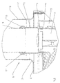
- a blower 2 is arranged on an exhaust manifold 3 in a vacuum chamber 6.
- an exhaust pipe is one on the outlet connector 14 via a sliding connector 1 combined exhaust air line 15 connected.
- the sliding connection 1 is with a captive clamping screw 4 on the connection connection 14 fixable.
- the vacuum chamber 6, which is provided with a cover 8, is with a Provided connection piece 7, on which the outer air pipe 10 of the exhaust air line 15 is fastened with a clamp 11.
- Fig. 2 is to connect an inner exhaust pipe 9 of the combined exhaust-air line 15 of the sliding connector 1 is provided, which with a Sliding seal 12, which is held in a circumferential bead 13 of the sliding connector 1, which is arranged in an end region of the sliding connector 1.
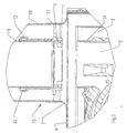
- This sliding connector 1 can, if necessary, as shown in FIG. 3, along the Exhaust pipe 9 are pushed up. This enables very easy access to the Blower 2 and the exhaust manifold 3 and it is thereby easier to remove the same.
Landscapes
- Engineering & Computer Science (AREA)
- Mechanical Engineering (AREA)
- General Engineering & Computer Science (AREA)
- Quick-Acting Or Multi-Walled Pipe Joints (AREA)
- Jet Pumps And Other Pumps (AREA)
- Exhaust Gas After Treatment (AREA)
- Compressor (AREA)
- Gasket Seals (AREA)
- Exhaust Silencers (AREA)
- Flanged Joints, Insulating Joints, And Other Joints (AREA)
Abstract
Description
Claims (2)
- Anschlußeinrichtung für ein kombiniertes Luft- Abgasrohr (15) an eine Unterdruckkammer (6), bzw. ein Abgasgebläse (2), insbesondere eines Heizgerätes, bei welcher Anschlußeinrichtung das äußere, Luft führende Rohr (10) mit einer Schelle (11) an einem Anschlußstutzen (7) der Unterdruckkammer (6) angeschlossen ist, dadurch gekennzeichnet, daß das Abgasrohr (9) über einen mit einer Gleitdichtung (12) versehenen Schiebestutzen (1) mit einem Auslaßstutzen (14) des Gebläses (2) verbunden ist.
- Anschlußeinrichtung nach Anspruch 1, dadurch gekennzeichnet, daß der Schiebestutzen (1) an seinem einen Ende stirnseitig mit einer umlaufenden Rille (5) versehen ist, mit dem der Auslaßstutzen (14) des Gebläses (2) in Eingriff bringbar ist.
Applications Claiming Priority (2)
| Application Number | Priority Date | Filing Date | Title |
|---|---|---|---|
| AT0142500A AT503704B1 (de) | 2000-08-18 | 2000-08-18 | Anschlusseinrichtung |
| AT14252000 | 2000-08-18 |
Publications (3)
| Publication Number | Publication Date |
|---|---|
| EP1180643A2 true EP1180643A2 (de) | 2002-02-20 |
| EP1180643A3 EP1180643A3 (de) | 2002-08-21 |
| EP1180643B1 EP1180643B1 (de) | 2008-04-02 |
Family
ID=3688218
Family Applications (1)
| Application Number | Title | Priority Date | Filing Date |
|---|---|---|---|
| EP01119395A Expired - Lifetime EP1180643B1 (de) | 2000-08-18 | 2001-08-11 | Anschlusseinrichtung für ein kombiniertes Luft-Abgasrohr |
Country Status (4)
| Country | Link |
|---|---|
| EP (1) | EP1180643B1 (de) |
| AT (2) | AT503704B1 (de) |
| DE (2) | DE50113808D1 (de) |
| ES (1) | ES2303515T3 (de) |
Family Cites Families (7)
| Publication number | Priority date | Publication date | Assignee | Title |
|---|---|---|---|---|
| DE8604045U1 (de) * | 1986-02-12 | 1986-04-10 | Joh. Vaillant Gmbh U. Co, 5630 Remscheid | Verschließbare Sichtöffnung |
| DE3632890A1 (de) * | 1986-09-27 | 1988-04-07 | Bruno Lampka | Anschlussstutzen zum einbau in schamottewaende |
| DE3704130C2 (de) * | 1987-02-11 | 1995-06-22 | Bosch Gmbh Robert | Gasbeheizter Wassererhitzer mit einer geschlossenen Verbrennungskammer |
| DE8810212U1 (de) * | 1987-08-18 | 1988-09-22 | Joh. Vaillant Gmbh U. Co, 5630 Remscheid | Stoßverbindung für aus zwei konzentrischen Rohren bestehende Rohrschüsse |
| AT392530B (de) * | 1988-06-14 | 1991-04-25 | Rapido Waermetechnik Gmbh | Anschluss eines abgasfuehrungsrohres |
| AT399929B (de) * | 1992-10-02 | 1995-08-25 | Vaillant Gmbh | Verbindungseinrichtung |
| DE29810921U1 (de) * | 1998-06-18 | 1999-11-04 | Robert Bosch Gmbh, 70469 Stuttgart | Abgasanschluß für gasbeheizte Wandgeräte, insbesondere Wassererhitzer |
-
2000
- 2000-08-18 AT AT0142500A patent/AT503704B1/de not_active IP Right Cessation
-
2001
- 2001-08-11 EP EP01119395A patent/EP1180643B1/de not_active Expired - Lifetime
- 2001-08-11 DE DE50113808T patent/DE50113808D1/de not_active Expired - Lifetime
- 2001-08-11 AT AT01119395T patent/ATE391268T1/de active
- 2001-08-11 ES ES01119395T patent/ES2303515T3/es not_active Expired - Lifetime
- 2001-08-13 DE DE10139325A patent/DE10139325A1/de not_active Withdrawn
Also Published As
| Publication number | Publication date |
|---|---|
| ES2303515T3 (es) | 2008-08-16 |
| EP1180643A3 (de) | 2002-08-21 |
| AT503704A1 (de) | 2007-12-15 |
| AT503704B1 (de) | 2008-06-15 |
| ATE391268T1 (de) | 2008-04-15 |
| DE50113808D1 (de) | 2008-05-15 |
| DE10139325A1 (de) | 2002-04-25 |
| EP1180643B1 (de) | 2008-04-02 |
Similar Documents
| Publication | Publication Date | Title |
|---|---|---|
| DE4425863A1 (de) | Saug- und Blasvorrichtung | |
| DE20013534U1 (de) | Vorrichtung zur Rückführung von Gas an einem Verbrennungsmotor | |
| DE2305470A1 (de) | Abscheider | |
| DE3305126A1 (de) | Klimageraet | |
| DE19915701C2 (de) | Anschlussgarnitur für einen Plattenheizkörper | |
| EP0305681A1 (de) | Schwenkbarer Handhabungsgriff | |
| EP1180643B1 (de) | Anschlusseinrichtung für ein kombiniertes Luft-Abgasrohr | |
| EP0913634B1 (de) | Gasbrenner | |
| DE19545029C1 (de) | Belüftungsvorrichtung für Fahrzeuge | |
| DE9314195U1 (de) | Befestigung eines Rohres | |
| EP0263333A2 (de) | Drall-Luftauslass | |
| EP3129617A1 (de) | Modulare abgasnachbehandlungsvorrichtung für ein abgassystem einer brennkraftmaschine | |
| DE102019002290A1 (de) | Verschlusskappe | |
| EP0328094A2 (de) | Doppelrohr sowie Verbindung koaxialer Doppelrohrschüsse mittels eines aus einem solchen Doppelrohr bestehenden Verbindungsstückes | |
| EP0629819B1 (de) | Anschlussgruppenstück für automatische Heizölentlüfter | |
| EP0617244A2 (de) | Luftheizgerät | |
| DE102018001137B3 (de) | Verbrennungsmotoraggregat | |
| DE19821360A1 (de) | Luftfilter, insbesondere Ansaugluftfilter für Brennkraftmaschinen | |
| AT392727B (de) | Dunstabzugshaube zur anordnung ueber einen kuechenherd oder dgl. | |
| DE9319686U1 (de) | Kombinierte Luft-/Abgasführung | |
| AT403205B (de) | Heizkessel | |
| DE1094058B (de) | Loesbare Verbindung von Rohren, insbesondere Fahrrohren in Zettelrohrpostanlagen | |
| DE102019135091A1 (de) | Behandlungsvorrichtung zur Behandlung von insbesondere flüssigen Fluiden sowie Behandlungseinheit und Anschlusskopf einer Behandlungsvorrichtung | |
| EP2105679B1 (de) | Heizkessel | |
| DE29502369U1 (de) | Luftleitung für ein mit einem Brenner versehenes Heizgerät |
Legal Events
| Date | Code | Title | Description |
|---|---|---|---|
| PUAI | Public reference made under article 153(3) epc to a published international application that has entered the european phase |
Free format text: ORIGINAL CODE: 0009012 |
|
| AK | Designated contracting states |
Kind code of ref document: A2 Designated state(s): AT BE CH CY DE DK ES FI FR GB GR IE IT LI LU MC NL PT SE TR |
|
| AX | Request for extension of the european patent |
Free format text: AL;LT;LV;MK;RO;SI |
|
| PUAL | Search report despatched |
Free format text: ORIGINAL CODE: 0009013 |
|
| AK | Designated contracting states |
Kind code of ref document: A3 Designated state(s): AT BE CH CY DE DK ES FI FR GB GR IE IT LI LU MC NL PT SE TR |
|
| AX | Request for extension of the european patent |
Free format text: AL;LT;LV;MK;RO;SI |
|
| 17P | Request for examination filed |
Effective date: 20030116 |
|
| 17Q | First examination report despatched |
Effective date: 20030326 |
|
| AKX | Designation fees paid |
Designated state(s): AT BE CH CY DE DK ES FI FR GB GR IE IT LI LU MC NL PT SE TR |
|
| GRAP | Despatch of communication of intention to grant a patent |
Free format text: ORIGINAL CODE: EPIDOSNIGR1 |
|
| GRAS | Grant fee paid |
Free format text: ORIGINAL CODE: EPIDOSNIGR3 |
|
| GRAA | (expected) grant |
Free format text: ORIGINAL CODE: 0009210 |
|
| AK | Designated contracting states |
Kind code of ref document: B1 Designated state(s): AT BE CH CY DE DK ES FI FR GB GR IE IT LI LU MC NL PT SE TR |
|
| REG | Reference to a national code |
Ref country code: GB Ref legal event code: FG4D Free format text: NOT ENGLISH |
|
| REG | Reference to a national code |
Ref country code: CH Ref legal event code: EP Ref country code: IE Ref legal event code: FG4D Free format text: LANGUAGE OF EP DOCUMENT: GERMAN |
|
| REF | Corresponds to: |
Ref document number: 50113808 Country of ref document: DE Date of ref document: 20080515 Kind code of ref document: P |
|
| REG | Reference to a national code |
Ref country code: ES Ref legal event code: FG2A Ref document number: 2303515 Country of ref document: ES Kind code of ref document: T3 |
|
| NLV1 | Nl: lapsed or annulled due to failure to fulfill the requirements of art. 29p and 29m of the patents act | ||
| REG | Reference to a national code |
Ref country code: IE Ref legal event code: FD4D |
|
| PG25 | Lapsed in a contracting state [announced via postgrant information from national office to epo] |
Ref country code: PT Free format text: LAPSE BECAUSE OF FAILURE TO SUBMIT A TRANSLATION OF THE DESCRIPTION OR TO PAY THE FEE WITHIN THE PRESCRIBED TIME-LIMIT Effective date: 20080902 Ref country code: FI Free format text: LAPSE BECAUSE OF FAILURE TO SUBMIT A TRANSLATION OF THE DESCRIPTION OR TO PAY THE FEE WITHIN THE PRESCRIBED TIME-LIMIT Effective date: 20080402 Ref country code: NL Free format text: LAPSE BECAUSE OF FAILURE TO SUBMIT A TRANSLATION OF THE DESCRIPTION OR TO PAY THE FEE WITHIN THE PRESCRIBED TIME-LIMIT Effective date: 20080402 |
|
| PGFP | Annual fee paid to national office [announced via postgrant information from national office to epo] |
Ref country code: FR Payment date: 20080606 Year of fee payment: 8 |
|
| EN | Fr: translation not filed | ||
| PG25 | Lapsed in a contracting state [announced via postgrant information from national office to epo] |
Ref country code: DK Free format text: LAPSE BECAUSE OF FAILURE TO SUBMIT A TRANSLATION OF THE DESCRIPTION OR TO PAY THE FEE WITHIN THE PRESCRIBED TIME-LIMIT Effective date: 20080402 Ref country code: SE Free format text: LAPSE BECAUSE OF FAILURE TO SUBMIT A TRANSLATION OF THE DESCRIPTION OR TO PAY THE FEE WITHIN THE PRESCRIBED TIME-LIMIT Effective date: 20080702 Ref country code: IE Free format text: LAPSE BECAUSE OF FAILURE TO SUBMIT A TRANSLATION OF THE DESCRIPTION OR TO PAY THE FEE WITHIN THE PRESCRIBED TIME-LIMIT Effective date: 20080402 |
|
| PLBE | No opposition filed within time limit |
Free format text: ORIGINAL CODE: 0009261 |
|
| STAA | Information on the status of an ep patent application or granted ep patent |
Free format text: STATUS: NO OPPOSITION FILED WITHIN TIME LIMIT |
|
| 26N | No opposition filed |
Effective date: 20090106 |
|
| PG25 | Lapsed in a contracting state [announced via postgrant information from national office to epo] |
Ref country code: MC Free format text: LAPSE BECAUSE OF NON-PAYMENT OF DUE FEES Effective date: 20080831 |
|
| GBPC | Gb: european patent ceased through non-payment of renewal fee |
Effective date: 20080811 |
|
| PG25 | Lapsed in a contracting state [announced via postgrant information from national office to epo] |
Ref country code: BE Free format text: LAPSE BECAUSE OF NON-PAYMENT OF DUE FEES Effective date: 20080831 |
|
| PG25 | Lapsed in a contracting state [announced via postgrant information from national office to epo] |
Ref country code: CY Free format text: LAPSE BECAUSE OF FAILURE TO SUBMIT A TRANSLATION OF THE DESCRIPTION OR TO PAY THE FEE WITHIN THE PRESCRIBED TIME-LIMIT Effective date: 20080402 |
|
| PG25 | Lapsed in a contracting state [announced via postgrant information from national office to epo] |
Ref country code: GB Free format text: LAPSE BECAUSE OF NON-PAYMENT OF DUE FEES Effective date: 20080811 |
|
| PG25 | Lapsed in a contracting state [announced via postgrant information from national office to epo] |
Ref country code: LU Free format text: LAPSE BECAUSE OF NON-PAYMENT OF DUE FEES Effective date: 20080811 |
|
| PG25 | Lapsed in a contracting state [announced via postgrant information from national office to epo] |
Ref country code: TR Free format text: LAPSE BECAUSE OF FAILURE TO SUBMIT A TRANSLATION OF THE DESCRIPTION OR TO PAY THE FEE WITHIN THE PRESCRIBED TIME-LIMIT Effective date: 20080402 |
|
| PG25 | Lapsed in a contracting state [announced via postgrant information from national office to epo] |
Ref country code: GR Free format text: LAPSE BECAUSE OF FAILURE TO SUBMIT A TRANSLATION OF THE DESCRIPTION OR TO PAY THE FEE WITHIN THE PRESCRIBED TIME-LIMIT Effective date: 20080703 |
|
| PG25 | Lapsed in a contracting state [announced via postgrant information from national office to epo] |
Ref country code: FR Free format text: LAPSE BECAUSE OF FAILURE TO SUBMIT A TRANSLATION OF THE DESCRIPTION OR TO PAY THE FEE WITHIN THE PRESCRIBED TIME-LIMIT Effective date: 20090123 |
|
| PGFP | Annual fee paid to national office [announced via postgrant information from national office to epo] |
Ref country code: DE Payment date: 20150803 Year of fee payment: 15 Ref country code: ES Payment date: 20150701 Year of fee payment: 15 Ref country code: CH Payment date: 20150805 Year of fee payment: 15 |
|
| PGFP | Annual fee paid to national office [announced via postgrant information from national office to epo] |
Ref country code: AT Payment date: 20150803 Year of fee payment: 15 |
|
| PGFP | Annual fee paid to national office [announced via postgrant information from national office to epo] |
Ref country code: IT Payment date: 20150831 Year of fee payment: 15 |
|
| REG | Reference to a national code |
Ref country code: DE Ref legal event code: R119 Ref document number: 50113808 Country of ref document: DE |
|
| REG | Reference to a national code |
Ref country code: CH Ref legal event code: PL |
|
| REG | Reference to a national code |
Ref country code: AT Ref legal event code: MM01 Ref document number: 391268 Country of ref document: AT Kind code of ref document: T Effective date: 20160811 |
|
| PG25 | Lapsed in a contracting state [announced via postgrant information from national office to epo] |
Ref country code: LI Free format text: LAPSE BECAUSE OF NON-PAYMENT OF DUE FEES Effective date: 20160831 Ref country code: CH Free format text: LAPSE BECAUSE OF NON-PAYMENT OF DUE FEES Effective date: 20160831 |
|
| PG25 | Lapsed in a contracting state [announced via postgrant information from national office to epo] |
Ref country code: AT Free format text: LAPSE BECAUSE OF NON-PAYMENT OF DUE FEES Effective date: 20160811 |
|
| PG25 | Lapsed in a contracting state [announced via postgrant information from national office to epo] |
Ref country code: DE Free format text: LAPSE BECAUSE OF NON-PAYMENT OF DUE FEES Effective date: 20170301 |
|
| PG25 | Lapsed in a contracting state [announced via postgrant information from national office to epo] |
Ref country code: IT Free format text: LAPSE BECAUSE OF NON-PAYMENT OF DUE FEES Effective date: 20160811 |
|
| PG25 | Lapsed in a contracting state [announced via postgrant information from national office to epo] |
Ref country code: ES Free format text: LAPSE BECAUSE OF NON-PAYMENT OF DUE FEES Effective date: 20160812 |
|
| REG | Reference to a national code |
Ref country code: ES Ref legal event code: FD2A Effective date: 20180625 |