EP1180248B1 - Verfahren zum befestigen einer ferrule an einem lichtwellenleiter - Google Patents
Verfahren zum befestigen einer ferrule an einem lichtwellenleiter Download PDFInfo
- Publication number
- EP1180248B1 EP1180248B1 EP00919086A EP00919086A EP1180248B1 EP 1180248 B1 EP1180248 B1 EP 1180248B1 EP 00919086 A EP00919086 A EP 00919086A EP 00919086 A EP00919086 A EP 00919086A EP 1180248 B1 EP1180248 B1 EP 1180248B1
- Authority
- EP
- European Patent Office
- Prior art keywords
- ferrule
- optical waveguide
- laser
- casing
- optical fiber
- Prior art date
- Legal status (The legal status is an assumption and is not a legal conclusion. Google has not performed a legal analysis and makes no representation as to the accuracy of the status listed.)
- Revoked
Links
- 230000003287 optical effect Effects 0.000 title claims description 43
- 238000000034 method Methods 0.000 title claims description 24
- 238000003466 welding Methods 0.000 claims description 13
- 230000005540 biological transmission Effects 0.000 claims description 5
- 238000001746 injection moulding Methods 0.000 claims description 3
- 229920002994 synthetic fiber Polymers 0.000 claims 4
- 239000011796 hollow space material Substances 0.000 claims 1
- 239000013307 optical fiber Substances 0.000 description 42
- 239000004033 plastic Substances 0.000 description 8
- 229920003023 plastic Polymers 0.000 description 8
- 239000000835 fiber Substances 0.000 description 5
- 239000000463 material Substances 0.000 description 5
- 238000005253 cladding Methods 0.000 description 4
- 230000000694 effects Effects 0.000 description 3
- 230000008878 coupling Effects 0.000 description 2
- 238000010168 coupling process Methods 0.000 description 2
- 238000005859 coupling reaction Methods 0.000 description 2
- 230000006735 deficit Effects 0.000 description 2
- 238000004519 manufacturing process Methods 0.000 description 2
- 230000004323 axial length Effects 0.000 description 1
- 238000002788 crimping Methods 0.000 description 1
- 238000013016 damping Methods 0.000 description 1
- 230000001419 dependent effect Effects 0.000 description 1
- 238000011161 development Methods 0.000 description 1
- 230000018109 developmental process Effects 0.000 description 1
- 238000005516 engineering process Methods 0.000 description 1
- 238000000605 extraction Methods 0.000 description 1
- 239000000155 melt Substances 0.000 description 1
- 230000035515 penetration Effects 0.000 description 1
- 230000001681 protective effect Effects 0.000 description 1
- 238000002604 ultrasonography Methods 0.000 description 1
Images

Classifications
-
- G—PHYSICS
- G02—OPTICS
- G02B—OPTICAL ELEMENTS, SYSTEMS OR APPARATUS
- G02B6/00—Light guides; Structural details of arrangements comprising light guides and other optical elements, e.g. couplings
- G02B6/24—Coupling light guides
- G02B6/36—Mechanical coupling means
- G02B6/38—Mechanical coupling means having fibre to fibre mating means
- G02B6/3807—Dismountable connectors, i.e. comprising plugs
- G02B6/3833—Details of mounting fibres in ferrules; Assembly methods; Manufacture
- G02B6/3855—Details of mounting fibres in ferrules; Assembly methods; Manufacture characterised by the method of anchoring or fixing the fibre within the ferrule
Definitions
- the present invention relates to a ferrule for a Optical fiber and a method of attaching one Ferrule on an optical fiber.
- electro-optical transmitters such as LEDs and laser diodes and electro-optical receivers, such as photodiodes and phototransistors
- electro-optical receivers such as photodiodes and phototransistors
- the attachment of the ferrule on or on the optical fiber must be tensile without damaging the optical fiber or even to influence its optical properties.
- a ferrule for an optical fiber or a method of attaching a ferrule to a To create optical fibers being a safe Attaching the ferrule to the optical fiber, too when used in a motor vehicle, for high Extraction forces is given.
- an optical Damping if possible do not occur and the manufacturing allow short cycle times by means of the method and cause low cost.
- This task is accomplished by a ferrule with a Optical waveguide according to claim 1 solved or solved by a method according to claim 8.
- a ferrule according to the invention is characterized by an optical fiber through the features of Claim 1 from.
- the method according to the invention comprises for attaching a ferrule to an optical fiber Steps according to claim 8.
- the ferrule which is made of a plastic that is in Regarding the laser light used more transparent than that
- the cladding of the optical fiber is also made of a plastic, by means of laser welding at the interface between ferrule and Optical fiber jacket, attached to the optical fiber.
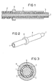
- a ferrule for an optical waveguide and the inventive method for attaching a ferrule on an optical fiber are shown in the drawings.
- FIG 1 is a ferrule 4 made of a plastic material arranged on an optical fiber 1, which is also made of is made of a plastic material.
- the optical waveguide 1 has in the illustrated embodiment a light-conducting core and a double-shell Coat on, which consists of an outer jacket 2 and an inner jacket 3 exists.
- This two-shell or two-layer structure of the jacket of the optical waveguide 1 from the outer jacket 2 and the inner jacket 3 is not absolutely necessary for the present invention; the decisive factor is that for the attachment of the ferrule 4 a certain buffer is available which is used for fastening the ferrule 4 damage to the core of the optical fiber 1 prevented.
- the outer jacket 2 of the optical waveguide 1 in one Stripped area that corresponds approximately to the axial length of ferrule 4 equivalent.
- the stripped area is preferably slight longer than the ferrule 4, so that a small piece of the Optical fiber 1 overhangs the ferrule 4.
- a collar 6 is formed at the left end of the ferrule 4. This Collar 6 arrives when the ferrule 4 is pushed on Optical fiber 1 in contact with the outer jacket 2.
- the core of the optical waveguide 1 is in place Ferrule 4 protected by the inner jacket 3.
- Figure 2 is a perspective view shown on the optical fiber 1 ferrule 4 shown.
- the optical fiber 1 is here on the right Ferrule 4 over while on the left of the illustration the optical fiber is shown cut off.
- the ferrule 4 on the Optical fiber 1 attached. 3 are exemplary three areas 5, where the welded connection is made. Depending on the required strength of the Connection between ferrule 4 and optical fiber 1 can more or less areas 5 and also the extent of these Areas 5 can be varied.
- the optical fiber 1 and the ferrule 4 are by means of this Laser beam welding permanently and indissolubly with each other connected. The welding takes place between the Inner circumference of the ferrule 4 and the outer circumference of the inner jacket Third
- the ferrule 4 When the ferrule 4 is actually welded to the inner jacket 3 (protective jacket for the core of the FO) of the optical fiber 1 only the plastic on these two parts melted, and there is no significant impairment effected on the Lichcwellenleicer 1. Because the light guiding Fiber is not mechanically deformed, such as during crimping, there is no increase in optical attenuation.
- the pull-out force of the ferrule relative to the optical waveguide 1 is mainly determined by the quality of the scoff conclusion and determined by the cross section of the weld.
- This weld can be made with any number of around the Ferrule 4 circularly distributed lasers or by a central one Lasers are generated, which then have appropriate laser optics fed.
- the ferrule 4 Since the ferrule 4 is more transparent than the inner jacket 3 for the laser light used, can be welded using the transmission method, i.e. the Laser light beam the transparent ferrule 4 almost undiminished penetrates and its effect on the inner jacket 3 unfolded. There it is in the top layer of the inner jacket 3 absorbs, whereby the material is heated, melts and combines with the material of the ferrule 4.
- the laser must have a wavelength for this penetration process have, preferably in the so-called near infrared range lies.
- Plastics for the ferrule 4 and the inner jacket 3 of the optical fiber 1 are available, the one hand offer transparency for the ferrule 4 and on the other hand absorb the light well as the inner jacket 3.
- the inner surface of the ferrule 4 can have a smooth surface have or may not be smooth, then with recesses, recesses, ribs, webs, etc. to make this To facilitate welding. Especially smaller amounts of material, such as on a rib, can be done with the laser melted more easily and quickly than a full one smooth surface.
- a quick welding has the advantage that damage to the core of the optical waveguide 1 is excluded can be.
- Figures 4 and 5 is the finished end piece of the optical fiber 1 with ferrule 4 shown.
- the End face of the optical waveguide 1 is on the length of the Ferrule 4 shortened and finished.
- the face can be cut, sanded or with the Laser smoothed. In the latter case, the same laser can be used how to use for welding.
- a ferrule 4 according to the invention is distinguished for one Optical fiber 1 characterized in that the ferrule 4 from Plastic is made and that the ferrule 4 preferably more transparent than the cladding 2, 3 of the optical waveguide 1 is trained.
- a method according to the invention Version for attaching a ferrule 4 to an optical fiber 1 comprises the following steps: Stripping an outer jacket 2 of one end of the optical waveguide 1 and exposing an inner jacket 3 of the optical waveguide 1; Push the ferrule 4 onto the stripped area the optical fiber 1; and at least in some areas Welding the ferrule 4 on the contact surface to the inner jacket 3 of the optical fiber 1. Due to the transparency this ferrule 4 can in the so-called transmission method Laser light penetrate the ferrule 4 almost completely and in the outermost region of the cladding 2, 3 of the optical waveguide 1 unfold its effect.
Landscapes
- Physics & Mathematics (AREA)
- General Physics & Mathematics (AREA)
- Optics & Photonics (AREA)
- Mechanical Coupling Of Light Guides (AREA)
- Optical Couplings Of Light Guides (AREA)
- Lining Or Joining Of Plastics Or The Like (AREA)
- Laser Beam Processing (AREA)
Description
- Hochfeste Verbindung zwischen Ferrule und Lichtwellenleiter;
- Die Ferrule kann kostengünstig in Spritzgusstechnik gefertigt werden;
- Wirtschaftliche Kabelkonfektionierung und Fertigung der Ferrule;
- Hoher Automatisierungsgrad bei der Montage möglich;
- Montage der Ferrule an dem Lichtwellenleiter kann mit der Bearbeitung der Stirnfläche des Lichtwellenleiters kombiniert werden; und
- Keine Beeinträchtigung der optischen Eigenschaften des Lichtwellenleiters.
- Fig. 1
- eine Querschnittansicht eines Lichtwellenleiters mit einer aufgesetzten Ferrule im Längsschnitt;
- Fig. 2
- eine perspektivische Ansicht der Ferrule und eines Teils des Lichtwellenleiters nach der Figur 1;
- Fig. 3
- eine Querschnittansicht des Lichtwellenleiters und der aufgesetzten Ferrule im Radialschnitt;
- Fig. 4
- eine Querschnittansicht ähnlich der Figur 1, wobei jedoch eine Stirnfläche des Lichtwellenleiters bündig auf die Länge der Ferrule gekürzt ist; und
- Fig. 5
- eine weitere perspektivische Ansicht der Ferrule und des Lichtwellenleiters nach der Figur 4.
Claims (16)
- Ferrule (4) mit einem Lichtwellenleiter (1), wobei die Ferrule (4) aus Kunststoff hergestellt ist und die Ferrule (4) an einem Mantel (2, 3) des Lichtwellenleiters (1) verschweissbar ist, dadurch gekennzeichnet, dass die Ferrule (4) mittels einer Laserverschweissung im Durchstrahlverfahren an dem Lichtwellenleiter (1) befestigbar ist und die Ferrule (4) für das verwendete Laserlicht transparenter ist als der Mantel (2, 3).
- Ferrule (4) nach Anspruch 1,
dadurch gekennzeichnet, dass die Ferrule (4) im Wesentlichen eine hohlzylindrische Form aufweist, wobei der Lichtwellenleiter (1) durch den Hohlraum verläuft. - Ferrule (4) nach Anspruch 1 oder 2,
dadurch gekennzeichnet, dass die Ferrule (4) im Berührungsbereich mit dem Lichtwellenleiter (1) eine nicht glatte Oberfläche aufweist. - Ferrule (4) nach Anspruch 1 oder 2,
dadurch gekennzeichnet, dass die Ferrule (4) im Berührungsbereich mit dem Lichtwellenleiter (1) eine glatte Oberfläche aufweist. - Ferrule (4) nach einem der Ansprüche 1 bis 4,
dadurch gekennzeichnet, dass die Ferrule (4) mittels Spritzgiessen hergestellt ist. - Ferrule (4) nach einem der Ansprüche 1 bis 5,
dadurch gekennzeichnet, dass die Ferrule (4) am Ende, welches dem Ende des Lichtwellenleiters (1) gegenüberliegt, einen Bund (6) aufweist. - Ferrule (4) nach Anspruch 1,
dadurch gekennzeichnet, dass die Laserverschweissung zumindest bereichsweise im Berührungsbereich zwischen Ferrule (4) und Lichtwellenleiter (1) erfolgt. - Verfahren zum Befestigen einer Ferrule (4) an einem Lichtwellenleiter (1) mit folgenden Schritten:gekennzeichnet durch die Schritte:Axial bereichsweises Abisolieren eines Endes des Zylindrischen Lichtwellenleiters (1), wobei radial ein Teil eines Mantels (2, 3) des Lichtwellenleiters (1) entfernt wird;Aufschieben der Ferrule (4) auf den abisolierten Bereich des Lichtwellenleiters (1); undZumindest bereichsweises (5) Verschweissen der Ferrule (4) an der Berührungsfläche zum verbliebenen Mantel (2, 3) des Lichtwellenleiters (1),Verschweissen der Ferrule (4) mit dem Lichtwellenleiter (1) mittels eines Laserstrahles; undVerschweissen mittels eines Durchstrahlverfahrens, wobei die Ferrule (4) für das verwendete Laserlicht im Wesentlichen transparent ist und der Mantel (2, 3) des Lichtwellenleiters (1) das verwendete Laserlicht im Wesentlichen absorbiert.
- Verfahren nach Anspruch 8,
gekennzeichnet durch den Schritt:
Herstellen der Ferrule (4) aus einem Kunststoff. - Verfahren nach Anspruch 8 oder 9,
gekennzeichnet durch den Schritt:
Herstellen der Ferrule (4) mittels eines Spritzgussverfahrens. - Verfahren nach einem der Ansprüche 8 bis 10,
gekennzeichnet durch den Schritt:
Herstellen des Lichtwellenleiters (4) aus einem Kunststoff. - Verfahren nach einem der Ansprüche 8 bis 11,
gekennzeichnet durch den Schritt:
Herstellen des Mantels (2, 3), der aus einem Aussenmantel (2) und/oder einem Innenmantel (3) besteht, aus einem Kunststoff. - Verfahren nach Anspruch 8,
gekennzeichnet durch den Schritt:
Verwenden eines Lasers mit einer Wellenlänge des Laserlichtes im nahen Infrarotbereich. - verfahren nach einem der Ansprüche 8 bis 12,
gekennzeichnet durch den Schritt:
Verwenden eines CO2-Lasers. - Verfahren nach einem der Ansprüche 8 bis 14,
gekennzeichnet durch den Schritt:
Anordnen von mehreren, am Umfang der Ferrule (4) kreisförmig angebrachten Lasern. - Verfahren nach einem der Ansprüche 8 bis 14,
gekennzeichnet durch den Schritt:
Anordnen eines Lasers und Anordnen einer Laseroptik zum Verteilen des Laserlichtes des Lasers über den umfang der Ferrule (4).
Applications Claiming Priority (3)
| Application Number | Priority Date | Filing Date | Title |
|---|---|---|---|
| DE19919428 | 1999-04-28 | ||
| DE19919428A DE19919428C2 (de) | 1999-04-28 | 1999-04-28 | Kunststoff-Ferrule für einen Lichtwellenleiter und Verfahren zum Befestigen einer Ferrule an einem Lichtwellenleiter |
| PCT/IB2000/000521 WO2000067056A1 (de) | 1999-04-28 | 2000-04-26 | Verfahren zum befestigen einer ferrule an einem lichtwellenleiter |
Publications (2)
| Publication Number | Publication Date |
|---|---|
| EP1180248A1 EP1180248A1 (de) | 2002-02-20 |
| EP1180248B1 true EP1180248B1 (de) | 2003-01-02 |
Family
ID=7906224
Family Applications (1)
| Application Number | Title | Priority Date | Filing Date |
|---|---|---|---|
| EP00919086A Revoked EP1180248B1 (de) | 1999-04-28 | 2000-04-26 | Verfahren zum befestigen einer ferrule an einem lichtwellenleiter |
Country Status (6)
| Country | Link |
|---|---|
| US (1) | US6960027B1 (de) |
| EP (1) | EP1180248B1 (de) |
| JP (1) | JP2002543466A (de) |
| DE (2) | DE19919428C2 (de) |
| ES (1) | ES2187460T3 (de) |
| WO (1) | WO2000067056A1 (de) |
Cited By (1)
| Publication number | Priority date | Publication date | Assignee | Title |
|---|---|---|---|---|
| DE102011016709A1 (de) | 2011-04-11 | 2012-10-11 | Tyco Electronics Amp Gmbh | Kupplungselement für Lichtwellenleiter, Steckverbinder und Herstellungsverfahren |
Families Citing this family (27)
| Publication number | Priority date | Publication date | Assignee | Title |
|---|---|---|---|---|
| EP1179744A1 (de) * | 2000-08-07 | 2002-02-13 | Tyco Electronics Logistics AG | Ferrule für einen Lichtwellenleiter und Verfahren zum Befestigen einer Ferrule an einem Lichtwellenleiter |
| DE10065197A1 (de) * | 2000-12-20 | 2002-07-11 | Euromicron Werkzeuge Gmbh | Abbildungsoptik |
| US6740191B2 (en) * | 2001-02-22 | 2004-05-25 | Medtronic Ave, Inc. | Through-transmission welding of catheter components |
| DE10209461A1 (de) | 2002-03-05 | 2003-10-02 | Bernhard Schaefer Werkzeug Und | Verfahren und Vorrichtung zur Herstellung eines Lichtwellenleiterendes |
| DE10217104A1 (de) * | 2002-04-17 | 2003-11-06 | Tyco Electronics Amp Gmbh | Verfahren und Vorrichtung zum Anschweißen von Kontakten an Lichtwellenleiter |
| EP1380867B1 (de) * | 2002-07-13 | 2007-09-12 | Tyco Electronics AMP GmbH | Steckverbindergehäuse für Lichtwellenleiter |
| US6804439B1 (en) | 2003-09-09 | 2004-10-12 | Yazaki North America, Inc. | Method of attaching a fiber optic connector |
| US6902327B1 (en) | 2003-12-10 | 2005-06-07 | Yazaki North America, Inc. | Apparatus and method for laser welding a ferrule to a fiber optic cable |
| US7430352B2 (en) | 2005-07-29 | 2008-09-30 | Aculight Corporation | Multi-segment photonic-crystal-rod waveguides for amplification of high-power pulsed optical radiation and associated method |
| US7391561B2 (en) | 2005-07-29 | 2008-06-24 | Aculight Corporation | Fiber- or rod-based optical source featuring a large-core, rare-earth-doped photonic-crystal device for generation of high-power pulsed radiation and method |
| WO2007103898A2 (en) * | 2006-03-03 | 2007-09-13 | Aculight Corporation | Diode-laser-pump module with integrated signal ports for pumping amplifying fibers |
| US7768700B1 (en) | 2006-11-30 | 2010-08-03 | Lockheed Martin Corporation | Method and apparatus for optical gain fiber having segments of differing core sizes |
| US7471860B2 (en) * | 2007-05-11 | 2008-12-30 | Baker Hughes Incorporated | Optical fiber cable construction allowing rigid attachment to another structure |
| US8179594B1 (en) | 2007-06-29 | 2012-05-15 | Lockheed Martin Corporation | Method and apparatus for spectral-beam combining of fanned-in laser beams with chromatic-dispersion compensation using a plurality of diffractive gratings |
| US8526110B1 (en) | 2009-02-17 | 2013-09-03 | Lockheed Martin Corporation | Spectral-beam combining for high-power fiber-ring-laser systems |
| CN102576127A (zh) * | 2009-10-15 | 2012-07-11 | 康宁股份有限公司 | 用于大芯径光纤的光纤连接器和结构以及所述光纤连接器和结构的制作方法 |
| US20110091166A1 (en) * | 2009-10-15 | 2011-04-21 | Seldon David Benjamin | Fiber Optic Connectors and Structures for Large Core Optical Fibers and Methods for Making the Same |
| US8441718B2 (en) | 2009-11-23 | 2013-05-14 | Lockheed Martin Corporation | Spectrally beam combined laser system and method at eye-safer wavelengths |
| US8503840B2 (en) | 2010-08-23 | 2013-08-06 | Lockheed Martin Corporation | Optical-fiber array method and apparatus |
| DE112011101288T5 (de) | 2010-04-12 | 2013-02-07 | Lockheed Martin Corporation | Strahldiagnostik- und Rückkopplungssystem sowie Verfahren für spektralstrahlkombinierteLaser |
| US8998502B2 (en) * | 2010-09-03 | 2015-04-07 | Corning Incorporated | Fiber optic connectors and ferrules and methods for using the same |
| JP2012168294A (ja) * | 2011-02-10 | 2012-09-06 | Nitto Denko Corp | 光コネクタの製法 |
| US9322998B2 (en) | 2013-01-15 | 2016-04-26 | Corning Cable Systems Llc | Fiber optic connector |
| US9366872B2 (en) | 2014-02-18 | 2016-06-14 | Lockheed Martin Corporation | Apparatus and method for fiber-laser output-beam shaping for spectral beam combination |
| US9681793B2 (en) * | 2014-06-19 | 2017-06-20 | Novartis Ag | Surgical probe with interlocking attachment |
| US10598866B2 (en) * | 2015-11-18 | 2020-03-24 | Lumasense Technologies Holdings, Inc. | Low reflection fiber-optic connector |
| JP2018205387A (ja) * | 2017-05-31 | 2018-12-27 | 矢崎総業株式会社 | 光コネクタ |
Family Cites Families (39)
| Publication number | Priority date | Publication date | Assignee | Title |
|---|---|---|---|---|
| NL6413441A (de) | 1964-11-19 | 1966-05-20 | ||
| BE792903A (nl) | 1971-12-30 | 1973-06-18 | American Can Co | Laserstraal-lassen van kunststoffen buizen |
| FR2385107A1 (fr) | 1977-01-18 | 1978-10-20 | Souriau & Cie | Perfectionnements aux procedes pour preparer, en vue de sa connexion, une extremite d'un cable optique a faisceau de fibres et cable ainsi obtenu |
| US4424435A (en) | 1981-09-11 | 1984-01-03 | Itek Corporation | Low expansion laser welding arrangement |
| JPS60214931A (ja) | 1984-04-10 | 1985-10-28 | Toyota Motor Corp | 異種合成樹脂材料の接合方法 |
| EP0159169A3 (de) | 1984-04-09 | 1987-07-01 | Toyota Jidosha Kabushiki Kaisha | Verfahren zum Verbinden verschiedenartiger synthetischer Harze |
| US4726008A (en) | 1986-10-20 | 1988-02-16 | Eastman Kodak Company | Optical disk assembly |
| JPH0750217B2 (ja) | 1986-11-29 | 1995-05-31 | 富士通株式会社 | 光コネクタ用フエル−ル |
| JP2520896B2 (ja) | 1987-03-04 | 1996-07-31 | 株式会社フジクラ | 光コネクタにおける光フアイバとフエル−ルとの接合方法 |
| JPS63228112A (ja) | 1987-03-17 | 1988-09-22 | Matsushita Electric Ind Co Ltd | 半導体レ−ザ・光フアイバ結合モジユ−ル |
| FR2624041A1 (fr) | 1987-12-02 | 1989-06-09 | Otic Fischer & Porter | Procede de soudage au moyen d'un faisceau laser, notamment applicable au soudage de pieces en verre |
| DE3813570A1 (de) | 1988-04-22 | 1989-11-09 | Fraunhofer Ges Forschung | Verfahren zum fuegen von werkstuecken aus aufschmelzbarem werkstoff mit laserstrahlung |
| DE3822429A1 (de) | 1988-06-30 | 1990-01-04 | Siemens Ag | Lichtwellenleiter-kupplung |
| US4859827A (en) * | 1988-10-17 | 1989-08-22 | American Telephone And Telegraph Company | Method for welding relatively small parts |
| JPH02219008A (ja) | 1989-02-20 | 1990-08-31 | Mitsubishi Cable Ind Ltd | フェルール |
| US5279693A (en) | 1990-05-09 | 1994-01-18 | Lps Industries, Inc. | Welding thermoplastic material with a laser |
| EP0483569A1 (de) | 1990-10-29 | 1992-05-06 | Fmc Corporation | Vorrichtung zum Verschweissen von Kunststoffen |
| US5300162A (en) | 1990-11-29 | 1994-04-05 | Hoechst Aktiengesellschaft | Process for the production of an optical coupler for polymeric optical fibers |
| US5267959A (en) | 1991-11-29 | 1993-12-07 | Schneider, Inc. | Laser bonding of angioplasty balloon catheters |
| DE4140283A1 (de) * | 1991-12-06 | 1993-06-17 | Bundesrep Deutschland | Verfahren zur fixierung eines lichtwellenleiters |
| GB9126370D0 (en) | 1991-12-12 | 1992-02-12 | Shanning Laser Systems Ltd | Securing of bodies |
| JPH05233742A (ja) | 1992-02-24 | 1993-09-10 | Sekisui Chem Co Ltd | 配線材料の選択方法 |
| DE4225679A1 (de) | 1992-08-04 | 1994-02-10 | Proaqua Provita Deutschland Gm | Verfahren und Anlage zum Schweißen von Kunststoffeinzelteilen von Filterelementen oder -systemen für die Medizin- und Labortechnik |
| US5291570A (en) | 1992-09-09 | 1994-03-01 | Hobart Laser Products, Inc. | High power laser - optical fiber connection system |
| DE4232326A1 (de) | 1992-09-26 | 1994-03-31 | Sel Alcatel Ag | Koppelanordnung für die Kopplung einer optischen Faser an ein optoelektronisches Modul |
| TW260753B (de) | 1992-12-03 | 1995-10-21 | Du Pont | |
| GB2276584B (en) | 1993-04-01 | 1997-09-17 | British Gas Plc | Joining bodies of thermoplastic material |
| US5893959A (en) | 1994-03-31 | 1999-04-13 | Marquardt Gmbh | Workpiece of plastic and production process for such a workpiece |
| DE4421531C1 (de) | 1994-06-20 | 1995-10-12 | Zam Ev | Verfahren zur Herstellung einer Faser-Ferrule-Verbindung |
| DE4432081A1 (de) | 1994-09-09 | 1996-03-14 | Basf Ag | Verfahren zum Schweißverbinden von Kunststoffteilen |
| WO1997009811A1 (en) | 1995-09-06 | 1997-03-13 | Advanced Micro Devices, Inc. | Low jitter low power single ended driver |
| JPH1048462A (ja) | 1996-08-06 | 1998-02-20 | Seiko Instr Inc | 光コネクタ用フェルール |
| JP4102448B2 (ja) * | 1997-02-07 | 2008-06-18 | 旭化成エレクトロニクス株式会社 | 光信号伝送用多芯プラスチック光ファイバ |
| DE19726489C1 (de) | 1997-06-21 | 1999-02-11 | Hartmann & Braun Gmbh & Co Kg | Verfahren zur Herstellung einer mechanischen Verbindung zwischen einem dünnen metallischen Draht und einem Glaskörper |
| DE29712264U1 (de) | 1997-07-11 | 1998-11-12 | Sator Alexander Paul | Vorrichtung zum Verschweißen der Enden von rohrförmigen Behältern, insbesondere von Tuben |
| DE19746402A1 (de) | 1997-10-21 | 1999-04-22 | Fresenius Medical Care De Gmbh | Verfahren und Vorrichtung zum Verschweißen von Kunststoffolien, vorzugsweise von Polyolefin-Folien |
| DE19849026A1 (de) * | 1998-10-23 | 2000-04-27 | Bayerische Motoren Werke Ag | Verfahren zum Befestigen eines Lichtleitfaserendes in einer Kunststoffkontakthülse und entsprechend hergestellter Kunststoffkontakt |
| DE19906828B4 (de) | 1999-02-18 | 2004-07-08 | Ticona Gmbh | Polyesterformmasse Verfahren zu ihrer Herstellung und deren Verwendung zum Laserschweißen |
| DE19919191A1 (de) | 1999-04-29 | 2000-11-02 | Bielomatik Leuze & Co | Verfahren und Vorrichtung zum Schweißen |
-
1999
- 1999-04-28 DE DE19919428A patent/DE19919428C2/de not_active Expired - Lifetime
-
2000
- 2000-04-26 WO PCT/IB2000/000521 patent/WO2000067056A1/de not_active Ceased
- 2000-04-26 ES ES00919086T patent/ES2187460T3/es not_active Expired - Lifetime
- 2000-04-26 US US10/130,887 patent/US6960027B1/en not_active Expired - Lifetime
- 2000-04-26 JP JP2000615840A patent/JP2002543466A/ja active Pending
- 2000-04-26 EP EP00919086A patent/EP1180248B1/de not_active Revoked
- 2000-04-26 DE DE50001010T patent/DE50001010D1/de not_active Revoked
Cited By (2)
| Publication number | Priority date | Publication date | Assignee | Title |
|---|---|---|---|---|
| DE102011016709A1 (de) | 2011-04-11 | 2012-10-11 | Tyco Electronics Amp Gmbh | Kupplungselement für Lichtwellenleiter, Steckverbinder und Herstellungsverfahren |
| WO2012139914A1 (en) | 2011-04-11 | 2012-10-18 | Tyco Electronics Amp Gmbh | Coupling element for optical waveguide, plug connector and fabrication method |
Also Published As
| Publication number | Publication date |
|---|---|
| DE50001010D1 (de) | 2003-02-06 |
| DE19919428C2 (de) | 2001-12-06 |
| JP2002543466A (ja) | 2002-12-17 |
| EP1180248A1 (de) | 2002-02-20 |
| ES2187460T3 (es) | 2003-06-16 |
| DE19919428A1 (de) | 2000-11-23 |
| WO2000067056A1 (de) | 2000-11-09 |
| US6960027B1 (en) | 2005-11-01 |
Similar Documents
| Publication | Publication Date | Title |
|---|---|---|
| DE19919428C2 (de) | Kunststoff-Ferrule für einen Lichtwellenleiter und Verfahren zum Befestigen einer Ferrule an einem Lichtwellenleiter | |
| DE102008044938B4 (de) | Verfahren zur Terminierung von lichtleitenden Faserbündeln sowie Hülse mit einem Faserbündel | |
| DE2352874B2 (de) | Optischer lichtleiteranschluss und verfahren zu seiner herstellung | |
| DE10015867A1 (de) | Steckerbuchse und Kupplung für einen optischen Steckverbinder | |
| EP0996010A2 (de) | Verfahren zum Befestigen eines Lichtleitfaserendes in einer Kunststoffkontakthülse und entsprechend hergestellter Kunststoffkontakt | |
| DE2743626C2 (de) | Steckverbindung für lichtleitende, mehradrige Kabelstränge | |
| DE8105665U1 (de) | "verfahren und vorrichtung zum verbinden optischer elemente" | |
| WO2013064481A1 (de) | Optische transportfaser und verfahren zu deren herstellung | |
| EP1058139A1 (de) | Ferrule für einen Lichtwellenleiter und Verfahren zum Befestigen der Ferrule an dem Lichtwellenleiter | |
| DE69116246T2 (de) | Zugentlasteter Stecker für optische Fasern | |
| DE102010039153B4 (de) | Verfahren zum Verbinden eines in ein Faserverbundbauteil eingebetteten Lichtleiters mit einem externen Lichtleiter | |
| DE69926235T2 (de) | Steckerstift für optischen stecker, methode zu seiner herstellung und optischer stecker mit einem solchen steckerstift | |
| EP2764387B1 (de) | Kabelzugentlastung für kabel, insbesondere fiberoptische kabel | |
| DE4341417C2 (de) | Lichtwellenleiter-Endabschlußvorrichtung | |
| DE4219901A1 (de) | Lichtwellenleiter-Abschlußhülse | |
| DE4221040C2 (de) | Verfahren zur Herstellung eines Lichtwellenleitersteckers | |
| DE60119236T2 (de) | Optischer Steckverbinder | |
| DE19922555C2 (de) | Ferrule für einen Lichtwellenleiter und Verfahren zum Befestigen einer Ferrule an einem Lichtwellenleiter | |
| EP1179744A1 (de) | Ferrule für einen Lichtwellenleiter und Verfahren zum Befestigen einer Ferrule an einem Lichtwellenleiter | |
| DE102023118608B4 (de) | Rückreflexionsverminderter Lichtwellenleiterstecker sowie Lichtwellenleiterverbinder mit einem solchen | |
| DE19923416C2 (de) | Ferrule für einen Lichtwellenleiter, Verfahren zum Herstellen einer solchen Ferrule und Verfahren zum Befestigen einer Ferrule an einem Lichtwellenleiter | |
| DE19639184A1 (de) | Verbindungseinrichtung für mindestens einen Lichtwellenleiter enthaltende optische Übertragungselemente und Verfahren zur Herstellung einer Verbindung | |
| DE8706844U1 (de) | Stecker für Lichtwellenleiter | |
| DE3733987A1 (de) | Verfahren und vorrichtung zur herstellung von verbindungsstellen fuer lichtleitfasern an verbindungssteckern | |
| DE19605027C1 (de) | Aufnahmelager |
Legal Events
| Date | Code | Title | Description |
|---|---|---|---|
| PUAI | Public reference made under article 153(3) epc to a published international application that has entered the european phase |
Free format text: ORIGINAL CODE: 0009012 |
|
| 17P | Request for examination filed |
Effective date: 20011023 |
|
| AK | Designated contracting states |
Kind code of ref document: A1 Designated state(s): AT BE CH CY DE DK ES FI FR GB GR IE IT LI LU MC NL PT SE |
|
| AX | Request for extension of the european patent |
Free format text: AL;LT;LV;MK;RO;SI |
|
| TPAD | Observations by third parties |
Free format text: ORIGINAL CODE: EPIDOS TIPA |
|
| GRAH | Despatch of communication of intention to grant a patent |
Free format text: ORIGINAL CODE: EPIDOS IGRA |
|
| GRAH | Despatch of communication of intention to grant a patent |
Free format text: ORIGINAL CODE: EPIDOS IGRA |
|
| GRAA | (expected) grant |
Free format text: ORIGINAL CODE: 0009210 |
|
| AK | Designated contracting states |
Kind code of ref document: B1 Designated state(s): CH DE ES FR GB IT LI |
|
| REG | Reference to a national code |
Ref country code: GB Ref legal event code: FG4D Free format text: 20030102:NOT ENGLISH |
|
| REG | Reference to a national code |
Ref country code: CH Ref legal event code: EP |
|
| REG | Reference to a national code |
Ref country code: IE Ref legal event code: FG4D Free format text: GERMAN |
|
| REF | Corresponds to: |
Ref document number: 50001010 Country of ref document: DE Date of ref document: 20030206 Kind code of ref document: P |
|
| REG | Reference to a national code |
Ref country code: CH Ref legal event code: NV Representative=s name: RITSCHER & PARTNER AG PATENTANWAELTE |
|
| GBT | Gb: translation of ep patent filed (gb section 77(6)(a)/1977) |
Effective date: 20030501 |
|
| ET | Fr: translation filed | ||
| REG | Reference to a national code |
Ref country code: ES Ref legal event code: FG2A Ref document number: 2187460 Country of ref document: ES Kind code of ref document: T3 |
|
| LTIE | Lt: invalidation of european patent or patent extension |
Effective date: 20030102 |
|
| REG | Reference to a national code |
Ref country code: IE Ref legal event code: FD4D Ref document number: 1180248E Country of ref document: IE |
|
| PLBQ | Unpublished change to opponent data |
Free format text: ORIGINAL CODE: EPIDOS OPPO |
|
| PLBI | Opposition filed |
Free format text: ORIGINAL CODE: 0009260 |
|
| PLBQ | Unpublished change to opponent data |
Free format text: ORIGINAL CODE: EPIDOS OPPO |
|
| PLBI | Opposition filed |
Free format text: ORIGINAL CODE: 0009260 |
|
| PLAX | Notice of opposition and request to file observation + time limit sent |
Free format text: ORIGINAL CODE: EPIDOSNOBS2 |
|
| 26 | Opposition filed |
Opponent name: DELPHI TECHNOLOGIES, INC.PATENTANWALT Effective date: 20030926 Opponent name: SCHAEFER WERKZEUG- UND SONDERMASCHINENBAU Effective date: 20030924 |
|
| 26 | Opposition filed |
Opponent name: DELPHI TECHNOLOGIES, INC.PATENTANWALT Effective date: 20030926 Opponent name: SCHLEUNIGER HOLDING AG Effective date: 20031002 Opponent name: SCHAEFER WERKZEUG- UND SONDERMASCHINENBAU Effective date: 20030924 |
|
| PLAX | Notice of opposition and request to file observation + time limit sent |
Free format text: ORIGINAL CODE: EPIDOSNOBS2 |
|
| PLBB | Reply of patent proprietor to notice(s) of opposition received |
Free format text: ORIGINAL CODE: EPIDOSNOBS3 |
|
| RDAF | Communication despatched that patent is revoked |
Free format text: ORIGINAL CODE: EPIDOSNREV1 |
|
| APBP | Date of receipt of notice of appeal recorded |
Free format text: ORIGINAL CODE: EPIDOSNNOA2O |
|
| APAH | Appeal reference modified |
Free format text: ORIGINAL CODE: EPIDOSCREFNO |
|
| APBQ | Date of receipt of statement of grounds of appeal recorded |
Free format text: ORIGINAL CODE: EPIDOSNNOA3O |
|
| PGFP | Annual fee paid to national office [announced via postgrant information from national office to epo] |
Ref country code: ES Payment date: 20070426 Year of fee payment: 8 |
|
| PGFP | Annual fee paid to national office [announced via postgrant information from national office to epo] |
Ref country code: CH Payment date: 20070427 Year of fee payment: 8 |
|
| PGFP | Annual fee paid to national office [announced via postgrant information from national office to epo] |
Ref country code: DE Payment date: 20070531 Year of fee payment: 8 |
|
| APBU | Appeal procedure closed |
Free format text: ORIGINAL CODE: EPIDOSNNOA9O |
|
| RDAG | Patent revoked |
Free format text: ORIGINAL CODE: 0009271 |
|
| STAA | Information on the status of an ep patent application or granted ep patent |
Free format text: STATUS: PATENT REVOKED |
|
| PGFP | Annual fee paid to national office [announced via postgrant information from national office to epo] |
Ref country code: GB Payment date: 20070425 Year of fee payment: 8 |
|
| REG | Reference to a national code |
Ref country code: CH Ref legal event code: PL |
|
| 27W | Patent revoked |
Effective date: 20070918 |
|
| GBPR | Gb: patent revoked under art. 102 of the ep convention designating the uk as contracting state |
Free format text: 20070918 |
|
| PGFP | Annual fee paid to national office [announced via postgrant information from national office to epo] |
Ref country code: IT Payment date: 20070518 Year of fee payment: 8 |
|
| PGFP | Annual fee paid to national office [announced via postgrant information from national office to epo] |
Ref country code: FR Payment date: 20070417 Year of fee payment: 8 |