EP1179387A1 - Werkzeugmaschine mit Greifer und/oder Werkzeugmagazinsystem - Google Patents
Werkzeugmaschine mit Greifer und/oder Werkzeugmagazinsystem Download PDFInfo
- Publication number
- EP1179387A1 EP1179387A1 EP01117517A EP01117517A EP1179387A1 EP 1179387 A1 EP1179387 A1 EP 1179387A1 EP 01117517 A EP01117517 A EP 01117517A EP 01117517 A EP01117517 A EP 01117517A EP 1179387 A1 EP1179387 A1 EP 1179387A1
- Authority
- EP
- European Patent Office
- Prior art keywords
- tool
- gripper
- shank
- magazine
- gripping
- Prior art date
- Legal status (The legal status is an assumption and is not a legal conclusion. Google has not performed a legal analysis and makes no representation as to the accuracy of the status listed.)
- Granted
Links
Images


Classifications
-
- B—PERFORMING OPERATIONS; TRANSPORTING
- B23—MACHINE TOOLS; METAL-WORKING NOT OTHERWISE PROVIDED FOR
- B23Q—DETAILS, COMPONENTS, OR ACCESSORIES FOR MACHINE TOOLS, e.g. ARRANGEMENTS FOR COPYING OR CONTROLLING; MACHINE TOOLS IN GENERAL CHARACTERISED BY THE CONSTRUCTION OF PARTICULAR DETAILS OR COMPONENTS; COMBINATIONS OR ASSOCIATIONS OF METAL-WORKING MACHINES, NOT DIRECTED TO A PARTICULAR RESULT
- B23Q3/00—Devices holding, supporting, or positioning work or tools, of a kind normally removable from the machine
- B23Q3/155—Arrangements for automatic insertion or removal of tools, e.g. combined with manual handling
- B23Q3/1552—Arrangements for automatic insertion or removal of tools, e.g. combined with manual handling parts of devices for automatically inserting or removing tools
- B23Q3/15526—Storage devices; Drive mechanisms therefor
- B23Q3/15536—Non-rotary fixed racks
-
- B—PERFORMING OPERATIONS; TRANSPORTING
- B23—MACHINE TOOLS; METAL-WORKING NOT OTHERWISE PROVIDED FOR
- B23Q—DETAILS, COMPONENTS, OR ACCESSORIES FOR MACHINE TOOLS, e.g. ARRANGEMENTS FOR COPYING OR CONTROLLING; MACHINE TOOLS IN GENERAL CHARACTERISED BY THE CONSTRUCTION OF PARTICULAR DETAILS OR COMPONENTS; COMBINATIONS OR ASSOCIATIONS OF METAL-WORKING MACHINES, NOT DIRECTED TO A PARTICULAR RESULT
- B23Q11/00—Accessories fitted to machine tools for keeping tools or parts of the machine in good working condition or for cooling work; Safety devices specially combined with or arranged in, or specially adapted for use in connection with, machine tools
- B23Q11/08—Protective coverings for parts of machine tools; Splash guards
-
- B—PERFORMING OPERATIONS; TRANSPORTING
- B23—MACHINE TOOLS; METAL-WORKING NOT OTHERWISE PROVIDED FOR
- B23Q—DETAILS, COMPONENTS, OR ACCESSORIES FOR MACHINE TOOLS, e.g. ARRANGEMENTS FOR COPYING OR CONTROLLING; MACHINE TOOLS IN GENERAL CHARACTERISED BY THE CONSTRUCTION OF PARTICULAR DETAILS OR COMPONENTS; COMBINATIONS OR ASSOCIATIONS OF METAL-WORKING MACHINES, NOT DIRECTED TO A PARTICULAR RESULT
- B23Q11/00—Accessories fitted to machine tools for keeping tools or parts of the machine in good working condition or for cooling work; Safety devices specially combined with or arranged in, or specially adapted for use in connection with, machine tools
- B23Q11/10—Arrangements for cooling or lubricating tools or work
-
- B—PERFORMING OPERATIONS; TRANSPORTING
- B23—MACHINE TOOLS; METAL-WORKING NOT OTHERWISE PROVIDED FOR
- B23Q—DETAILS, COMPONENTS, OR ACCESSORIES FOR MACHINE TOOLS, e.g. ARRANGEMENTS FOR COPYING OR CONTROLLING; MACHINE TOOLS IN GENERAL CHARACTERISED BY THE CONSTRUCTION OF PARTICULAR DETAILS OR COMPONENTS; COMBINATIONS OR ASSOCIATIONS OF METAL-WORKING MACHINES, NOT DIRECTED TO A PARTICULAR RESULT
- B23Q7/00—Arrangements for handling work specially combined with or arranged in, or specially adapted for use in connection with, machine tools, e.g. for conveying, loading, positioning, discharging, sorting
- B23Q7/04—Arrangements for handling work specially combined with or arranged in, or specially adapted for use in connection with, machine tools, e.g. for conveying, loading, positioning, discharging, sorting by means of grippers
- B23Q7/043—Construction of the grippers
-
- Y—GENERAL TAGGING OF NEW TECHNOLOGICAL DEVELOPMENTS; GENERAL TAGGING OF CROSS-SECTIONAL TECHNOLOGIES SPANNING OVER SEVERAL SECTIONS OF THE IPC; TECHNICAL SUBJECTS COVERED BY FORMER USPC CROSS-REFERENCE ART COLLECTIONS [XRACs] AND DIGESTS
- Y10—TECHNICAL SUBJECTS COVERED BY FORMER USPC
- Y10S—TECHNICAL SUBJECTS COVERED BY FORMER USPC CROSS-REFERENCE ART COLLECTIONS [XRACs] AND DIGESTS
- Y10S414/00—Material or article handling
- Y10S414/124—Roll handlers
-
- Y—GENERAL TAGGING OF NEW TECHNOLOGICAL DEVELOPMENTS; GENERAL TAGGING OF CROSS-SECTIONAL TECHNOLOGIES SPANNING OVER SEVERAL SECTIONS OF THE IPC; TECHNICAL SUBJECTS COVERED BY FORMER USPC CROSS-REFERENCE ART COLLECTIONS [XRACs] AND DIGESTS
- Y10—TECHNICAL SUBJECTS COVERED BY FORMER USPC
- Y10S—TECHNICAL SUBJECTS COVERED BY FORMER USPC CROSS-REFERENCE ART COLLECTIONS [XRACs] AND DIGESTS
- Y10S483/00—Tool changing
- Y10S483/901—Robot end effectors
-
- Y—GENERAL TAGGING OF NEW TECHNOLOGICAL DEVELOPMENTS; GENERAL TAGGING OF CROSS-SECTIONAL TECHNOLOGIES SPANNING OVER SEVERAL SECTIONS OF THE IPC; TECHNICAL SUBJECTS COVERED BY FORMER USPC CROSS-REFERENCE ART COLLECTIONS [XRACs] AND DIGESTS
- Y10—TECHNICAL SUBJECTS COVERED BY FORMER USPC
- Y10S—TECHNICAL SUBJECTS COVERED BY FORMER USPC CROSS-REFERENCE ART COLLECTIONS [XRACs] AND DIGESTS
- Y10S483/00—Tool changing
- Y10S483/902—Tool grippers
-
- Y—GENERAL TAGGING OF NEW TECHNOLOGICAL DEVELOPMENTS; GENERAL TAGGING OF CROSS-SECTIONAL TECHNOLOGIES SPANNING OVER SEVERAL SECTIONS OF THE IPC; TECHNICAL SUBJECTS COVERED BY FORMER USPC CROSS-REFERENCE ART COLLECTIONS [XRACs] AND DIGESTS
- Y10—TECHNICAL SUBJECTS COVERED BY FORMER USPC
- Y10T—TECHNICAL SUBJECTS COVERED BY FORMER US CLASSIFICATION
- Y10T483/00—Tool changing
- Y10T483/17—Tool changing including machine tool or component
- Y10T483/1733—Rotary spindle machine tool [e.g., milling machine, boring, machine, grinding machine, etc.]
- Y10T483/1748—Tool changer between spindle and matrix
- Y10T483/1752—Tool changer between spindle and matrix including tool holder pivotable about axis
- Y10T483/1779—Linearly movable tool holder
-
- Y—GENERAL TAGGING OF NEW TECHNOLOGICAL DEVELOPMENTS; GENERAL TAGGING OF CROSS-SECTIONAL TECHNOLOGIES SPANNING OVER SEVERAL SECTIONS OF THE IPC; TECHNICAL SUBJECTS COVERED BY FORMER USPC CROSS-REFERENCE ART COLLECTIONS [XRACs] AND DIGESTS
- Y10—TECHNICAL SUBJECTS COVERED BY FORMER USPC
- Y10T—TECHNICAL SUBJECTS COVERED BY FORMER US CLASSIFICATION
- Y10T483/00—Tool changing
- Y10T483/18—Tool transfer to or from matrix
- Y10T483/1809—Matrix including means to latch tool
-
- Y—GENERAL TAGGING OF NEW TECHNOLOGICAL DEVELOPMENTS; GENERAL TAGGING OF CROSS-SECTIONAL TECHNOLOGIES SPANNING OVER SEVERAL SECTIONS OF THE IPC; TECHNICAL SUBJECTS COVERED BY FORMER USPC CROSS-REFERENCE ART COLLECTIONS [XRACs] AND DIGESTS
- Y10—TECHNICAL SUBJECTS COVERED BY FORMER USPC
- Y10T—TECHNICAL SUBJECTS COVERED BY FORMER US CLASSIFICATION
- Y10T483/00—Tool changing
- Y10T483/18—Tool transfer to or from matrix
- Y10T483/1818—Matrix including means to project tool for transfer
Definitions
- the invention relates to a tool magazine system for a machining spindle, with a gripper, which comes from a tool magazine Grips tools on a machining spindle to Example of a machining center or a machine tool leads and passes to the spindle.
- the aforementioned tool magazine systems are well known. You serve in machine tools, such as machining centers, Milling machines or lathes and so on, in particular for the metalworking industry, according to the given machining steps in the tool spindle in a short succession of different tools available put. As a rule, the tools are cutting tools, such as drills or milling cutters and the same. But it is quite possible instead of one Machining spindle to provide a machining head that optionally also has a tool spindle.
- the invention therefore has set itself the task of a tool magazine system, as described at the beginning improve that it is possible with the same space requirement higher number of tools in this tool magazine system reproach.
- the invention is based on one Tool magazine system, as described at the beginning, and strikes before that the gripper with respect to the axis of rotation or Longitudinal axis of the tool, laterally, especially in To the tool essentially at right angles to this axis is brought up and seizes this.
- This configuration ensures that it is possible to use tools essentially in the longitudinal axis To arrange a shelf vertically one above the other and still safe grasping and safe transport of the Allow tool. Since it is possible in principle, several The tool magazine is designed to store tools one on top of the other easily possible as a shelf, which makes the Space requirements can be significantly reduced.
- the invention is based on the arrangement of the tools in Longitudinal axis, for example vertically one above the other, in none wise limited. It is also possible in the same way Use invention in existing tool magazines, at which the tools, for example, flat or graded are arranged offset next to each other.
- the invention Tool magazine system also allows the recording of lying down stored tools, i.e. tools whose longitudinal axis in the Is oriented essentially horizontally.
- the gripper with respect the longitudinal / rotational axis of the tool to the side of the tool drives up.
- the gripping device is the tool or gripped the tool shank in the axial direction.
- the gripper is arranged on a handling device and mounted with multiple axes. This is about Example of a five- or six-axis system, with three translation axes and two, three or more axes of rotation for the gripper are provided.
- a drip pan to catch under the tool magazine of dragged-in coolant is provided and the Drip tray is connected to the coolant circuit.
- the Tool is sprayed with coolant during work, which on the one hand should lower the tool temperature and on the other hand should also wash away the detached chips.
- the coolant is in a cycle, the coolant after cleaning or filtering the washed-off Parts through a pump system to the tool respectively the workpiece is brought up and with high pressure is sprayed onto the tool or workpiece.
- the Dripping-wet tool will be at the end of each step from the gripper from the work spindle respectively removed from the processing head and transported back into the magazine.
- the adhering coolant also dragged into the tool magazine. This then drips in the pause time of the tool down and is by caught the drip tray proposed according to the invention, which the collected liquid to the coolant circuit feeds again.
- a drip plate is provided for the tools, such that the underlying tool in the sense of a rain canopy is protected from this liquid.
- the invention relates to a gripper for gripping, Transporting and / or transferring a tool, in particular for transporting a tool from a tool magazine to a work spindle, the tool in particular has a shaft, and on the lateral surface of the Shank or tool a groove, recess or a Paragraph is provided with which a first part of the gripper cooperates and a second part of the gripper with one interacts with another area of the shaft or tool.
- the design of the tool magazine system becomes an improved gripper in the same way suggested that the tool essentially allows rectangular or sideways with respect to its preferred axis is taken.
- gripping tools are in the Basically two different, competing systems known. On the one hand it is a so-called flap system, in which two elements are axial or pointed Angles are moved to this axis and the flaps are formed are that they look at the heels and stems respectively Hold the grooves or grooves in the tool.
- Another principle works like a pair of pliers, that is, it the tool is gripped axially. In the solution in the state of the Technology, however, regularly have special undercuts, Heels and so on on the tool or tool shank exploited to hold the tool.
- the now proposed embodiment of the Gripper therefore also allows a different gripping system, namely, according to the movement of the gripper, laterally or at right angles to the tool, to this. It is proposed that that the second part of the gripper on the shaft surface or lies against the outer diameter of the tool. Training the The second part is made so that not one Keeping on shoulders and axial grooves and so on must be, as was necessary in the prior art. Rather, the second part is on the outer surface of the shaft or tool outer diameter positioned that the tool is guided and fixed radially with respect to the gripper. The axial guidance is provided by the first part, which with a corresponding nose, a projection or also cooperates with a depression, groove and the like on the tool.
- the invention is not based on such an embodiment limited, but is also in the same way on a tool Can be used without a tool shank, then instead of the corresponding tool sheath Functionalities takes over. The same applies to tool types their shank compared to the effective tool areas is reset.
- the use of the shaft has, however, particularly in the automatic Machining workpieces a task, he defines the exact position of the tool due to contact surfaces in the longitudinal direction as well as with respect to the diameter for correspondingly precise processing.
- This is in particular a flat surface is provided on the shaft at right angles to the longitudinal axis, which is called the functional surface and highly accurate is processed.
- Known gripping principles have in particular Functional surface for holding the tool included. On such a principle is disadvantageous because, on the one hand, due to the Holding forces can damage the functional surface. Of Further can under the gripping part on the plane surface Chips and so on get stuck, which often happens with one blow-off step provided below for storage or retrieval of the tool in the magazine not of the tool be removed.
- Another advantage of the design of the gripper lies in that it is designed to be relatively space-saving, because the first part, for example, in the groove of the tool engages and the second part next to the shaft surface is applied. If this principle is mirrored on the longitudinal axis rectangular axis or plane, so can be arranged Gripper also in the groove and in another shaft area take. Because of this principle, it is also fundamental possible that two grippers simultaneously the tool take. But this is the basic requirement for a wrap-around system, which consists of two grippers.
- the configuration of the gripper according to the invention thus combines three advantages in itself, on the one hand, it allows space-saving Arrangement of the tools on a tool shelf, it allows without Using an additional wrap-around element of the workpiece immediately and the design of the gripper is chosen so that the functional surfaces for holding are not are required, i.e. also when inserting the tool into the Do not disturb the work spindle or the surfaces for Cleanings are accessible.
- first part and the second part are relative to each other is movable, in particular linearly movable with respect to one another or are pivotable.
- the proposed mobility allows the tool to be gripped, taking into account the real mobility be realized by three different principles can, namely only by moving the first or second Part or a movement of both parts.
- the first and the second part is either linearly movable with respect to one another, or swiveled towards each other, for example if a Part is articulated.
- first part is relatively stationary on the gripper and the second part is designed to be movable for this purpose.
- the first Part is preferably with a spring-like contact surface formed, which engages in a circumferential groove of the shaft, the second part, which is the radial fixation of the tool takes over (with axial determination by the first part), is for this purpose designed to be movable.
- the invention also relates to a machine tool either with a gripper, a tool magazine system or a wrap-around system as described.
- a Such a machine tool is used in particular for machining Machining workpieces, but it is also possible to To use machine tools for other purposes, for example to use this principle for assembly machines, too which corresponding assembly tools with the help of the invention be stored in the working head.
- 1, 2 is the tool magazine system according to the invention shown schematically.
- a tool magazine 3 are the Tools 2 are stored and are gripped by a gripper 1 if necessary taken.
- the tool magazine 3 is, for example from a tool rack with several shelves 30 one above the other.
- the shelves 30 have a vertical Back 33 on which the floors on a not shown Support wall or support frame or the like attachable are.
- Tool carrier 34 has on its front, the back opposite side, recesses 31 on the outside diameter of the tool or tool shank to be held 21 correspond and form the bearing device 31.
- recesses 31 In the tool carrier 34 are corresponding in the region of the recesses Molded paragraphs for this.
- a drip plate 32 is arranged above the tool 2 in order to Avoid getting a tool 2 that is still wet coolant onto an underlying tool drips down, especially on the sensitive ones Functional surfaces or receiving surfaces (HSK shank or steep taper shank) dirty.
- the configuration of the invention ensures that the Shelf 30 are arranged one above the other and therefore the entire tool magazine system is proportionate can be realized in a space-saving manner.
- the gripper 1 becomes rectangular brought up to the tool 2.
- the gripper 1 is by a handling device not shown along all Spatial axes and guided with respect to a plurality of axes of rotation / moves and has two parts 11 and 12.
- Fig. 3 the gripping of the tool 2 is in particular with two essentially identical grippers 10, 19 shown. First, however, the tool 2 should be gripped be dealt with in detail by the gripper 1.
- the gripper 1, 10, as already formed, consists of a Gripping arm 16, the two parts at its front end, namely has a first part 11 and a second part 12.
- the two Parts 11 and 12 work together in such a way that the tool 2 is kept safe.
- the second Part 12 oriented around a perpendicular to the longitudinal axis 20, usually swivel axis horizontally arranged, So movably mounted, whereas the first part 11 on the gripper arm 16 is fixed.
- the first part 11 points at least one contact surface 14, 14 'on (Fig. 4).
- This Contact surface 14 is spring-like, prismatic and corresponds in its contour to the shape of the circumferential groove 22 on the tool shank 21 or the tool 2.
- This Circumferential groove 22 is in the area of the design of the tools, widely used especially for cutting tools and as Standard.
- the shaft 21 on which the second part is present a larger diameter or outer dimensions has, like the rest of the tool 2, at the ensure claw-like configuration of the second part 12, that the claw over the half diameter of the tool shank 21 takes hold.
- the second part 12 is in the area of the smaller diameter is moved over the tool axis and then in a movement component in the direction of the longitudinal axis of the tool swiveled onto the shaft.
- a half diameter it describes the route to be overcome must to the outer areas of the claw-like part 12 behind the maximum outside diameter of the shank / tool position.
- cylindrical tool shank at least half the diameter to move accordingly into a corresponding receptacle, to allow the cylinder to reach behind the claw.
- FIG. 4 is a bottom view of the gripper 1 according to the invention.
- the investment areas 13, 13 ' are at a circumferential distance of less than 180 ° on the side facing the claw opening of the part 12, in cooperation with the stop surface 14 of the first part 11, the two remaining degrees of freedom flat possibility of movement in radial mobility eliminate.
- a cover 100 is provided on the second part 12, the but not necessarily in on the bottom with the tool To come into contact to achieve the holding effect. On the cover 100 can also be dispensed with.
- This configuration ensures that the functional surface is not damaged and also cleaned at any time can be.
- Fig. 4 it is shown that two contact surfaces 14, 14 'on the arranged first, here fixed first part 11 are in a circumferential distance of about 60 ° to 90 ° extends over a circumferential angle of approximately 30 °. This will achieved a safe storage of the tool 2.
- a position securing device 15 for example in the form of a sliding block provided that in a corresponding recess on the Tool engages.
- the contact surfaces 13, 13 'on the second part 12 are in the Rule edited precisely and allow a form-fitting, clamping Installation of the front area of the second part 12 the tool shank 21.
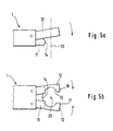
- FIG. 5b shows that the principle according to the invention is not only as a flap principle (Fig. 5a, or Fig. 3 and 4) is feasible, but also with the principle of pliers is feasible.
- the second part 12 consists of two Elements 17, 18 which cooperate like claws or pliers. For this purpose, they are articulated around pivot points and with appropriate Drives equipped.
- the first part 11 is located below the elements of the second part 12.
- the axis 20 of the tool 2 is with indicated by a cross, the tool 2 is otherwise not shown.
- the first and second Part 11, 12 is relatively movable to each other.
- an Drive provided, for example as a hydraulic or pneumatic working cylinder, which is integrated in the gripping arm 16 is, is formed or for example as an electric motor is realized. It is thus possible to operate as a third party
- To provide drive that is, the movement of the gripper exploit his handling device so that the gripper on appropriate stops is performed and then, due to the Drive of the gripper, the parts 11, 12 are moved. there can also be operated by the second gripper or through other elements on the machine tool and so on respectively.
- the mutually movable Parts 11, 12 or elements 17, 18 of the second part 12 to each other are fixable.
- fixation can also by appropriately trained working cylinders and such continue to take place.
- the guard locking is also, for example, by a hydraulic or pneumatic working cylinder causes.
- Corresponding springs compression, tension, or disc springs
- the working cylinder Becomes the working cylinder or the drive is not acted on, then the Force of these passive elements, for example the spring, as Tumbler.
- the working cylinder must be a correspondingly large Use force to overcome the force of guard locking.
- the contact surface first dips 14, 14 'of the first part 11 in the circumferential groove 22 of the Tool shank 21 a.
- the second part Before, at the same time or afterwards the second part is clamped to the Tool shaft 21 or the tool 2 brought up, the engages second part 12 on the lateral surface.
- the second part 12 moves onto the first Part 11 to, the second part 12 here a pivoting movement describes whose movement at the acute angle or is oriented almost parallel to the longitudinal axis 20.
- the first being second part 12 removed from the shaft 21 or workpiece 2 and overcomes the clamping by the first part 11 in its interaction with the tool 2 or the Tool shaft 21 forms a replacement for this.
- the clamping is overcome in one movement in the axial direction, the axial fixation of the tool by the first part is used as a reserve.
- this moves second part 12 in sections in the longitudinal direction so parallel to the longitudinal axis 20, but only a part 12 of the gripper 1 is moved.
- the gripper 1 as a whole becomes laterally, for example essentially at right angles to the longitudinal axis 20 to the Tool introduced and therefore allows in particular the vertical Arrangement of many tools on top of each other.
- Part 12 is pushed into an area over the tool, in which the diameter is smaller because of the claw-like formation of the second part 12 encompass the entire tool should.
- the part 12 is therefore positioned so that it in the narrower area overlaps the tool and then at an acute angle or essentially parallel to the longitudinal axis on the shaft listed and clamped to it.
- a vertical component or a component parallel to the longitudinal axis 20 of the second part 12 is in the The proposal according to 5b is dispensed with, since there is a forceps or claw movement of the two elements designed to be movable relative to one another 17 and 18 is provided.
- the gripping system here consists of two grippers 10, 19, which are constructed identically. On the identity of the two However, grippers are not important when using the invention.
- the two grippers 10, 19 are arranged so that they with respect to an axis perpendicular to the tool longitudinal axis 20 attack rotated on the tool on different sides.
- the configuration is special of the first part 11, 11 'chosen so that they are at opposite Engagement on the tool a gap between them form, that is, the first part 11 does not encompass the entire Semicircle of the tool shank 21.
- the second part 12, 12 ' overlaps the widest point of the diameter of tool 2 or tool shank 21, however on opposite sides of the shaft the groove 22. Due to the twisted arrangement, the two side parts 12, 12 'not, since they with respect to the Groove 22 attack different shaft sections.
Landscapes
- Engineering & Computer Science (AREA)
- Mechanical Engineering (AREA)
- Automatic Tool Replacement In Machine Tools (AREA)
- Percussive Tools And Related Accessories (AREA)
Abstract
Description
- Fig. 1, 2
- in einer perspektivischen Darstellung (Fig. 1) und in einer Seitenansicht (Fig. 2) das erfindungsgemäße Werkzeugmagazinsystem,
- Fig. 3
- in einer perspektivischen Darstellung zwei erfindungsgemäße Greifer in dem ebenfalls erfindungsgemäßen Umgreifsystem,
- Fig. 4
- in einer Draufsicht ein Detail des erfindungsgemäßen Greifers und
- Fig. 5a, 5b
- in einer Seitenansicht (Fig. 5a) beziehungsweise Draufsicht (Fig. 5b) zwei verschiedene Ausgestaltungen des Prinzipes des erfindungsgemäßen Greifers.
Claims (24)
- Werkzeugmagazinsystem für eine Bearbeitungsspindel oder einem Bearbeitungskopf, mit einem Greifer, mit einem Greifer, welcher aus einem Werkzeugmagazin Werkzeuge ergreift, an eine Bearbeitungsspindel, zum Beispiel eines Bearbeitungszentrums oder einer Werkzeugmaschine führt und an die Spindel oder Kopf übergibt, dadurch gekennzeichnet, daß der Greifer (1) bezüglich der Rotationsachse beziehungsweise Längsachse (20) des Werkzeuges (2) seitlich, insbesondere im Wesentlichen rechtwinklig zu dieser Achse an das Werkzeug (2) herangeführt wird und dieses ergreift.
- Werkzeugmagazinsystem nach Anspruch 1, dadurch gekennzeichnet, daß der Greifer (1) an einem Handhabungsgerät angeordnet ist und mehrachsig, beweglich gelagert ist.
- Werkzeugmagazinsystem nach einem oder beiden der vorhergehenden Ansprüche, dadurch gekennzeichnet, daß das Werkzeugmagazin (3) als Werkzeugregal ausgebildet ist, in welchem mindestens zwei Böden (30) im Wesentlichen übereinander angeordnet sind und die Böden (30) in entsprechenden Lagervorrichtungen (31) die Werkzeuge (2) halten.
- Werkzeugmagazinsystem nach einem oder mehreren der vorhergehenden Ansprüche, dadurch gekennzeichnet, daß über der Lagervorrichtung (31) ein Tropfblech (32) vorgesehen ist.
- Werkzeugmagazinsystem nach einem oder mehreren der vorhergehenden Ansprüche, dadurch gekennzeichnet, daß unter dem Werkzeugmagazin eine Tropfwanne zum Auffangen von verschleppter Kühlflüssigkeit vorgesehen ist und die Tropfwanne mit dem Kühlflüssigkeitskreislauf verbunden ist.
- Greifer für das Greifen, Transportieren und/oder Übergeben eines Werkzeuges, insbesondere für den Transport eines Werkzeuges aus einem Werkzeugmagazin zu einer Arbeitsspindel, wobei das Werkzeug insbesondere einen Schaft aufweist, und an der Mantelfläche des Schaftes oder des Werkzeuges eine Rille, Vertiefung, ein Absatz oder dergleichen vorgesehen ist, mit welchem ein erstes Teil des Greifers zusammenwirkt und ein zweites Teil des Greifers mit einem anderen Bereich des Schaftes oder des Werkzeuges zusammenwirkt, dadurch gekennzeichnet, daß der zweite Teil (12) des Greifers an der Schaftmantelfläche (21) oder am Werkzeugaußendurchmesser anliegt.
- Greifer nach Anspruch 6, dadurch gekennzeichnet, daß der zweite Teil (12) mindestens zwei Anlageflächen (13, 13') aufweist und sich das Werkzeug (2) im Greifer (1) zwischen diesen Anlageflächen (13, 13') befindet und klemmend gehalten ist.
- Greifern nach einem oder beiden der vorhergehenden Ansprüche 6 und 7, dadurch gekennzeichnet, daß der zweite Teil (12) klauenartig ausgebildet ist und die Klaue mindestens den Halbdurchmesser des Werkzeugschaftes (21) beziehungsweise des Werkzeuges (2) übergreift.
- Greifer nach einem oder mehreren der vorhergehenden Ansprüche 6 bis 8, dadurch gekennzeichnet, daß das erste Teil (11) mindestens eine federartige Anlagefläche (14) aufweist, die in eine Umfangsrille oder -nut (22) des Werkzeugschaftes (21) oder des Werkzeuges (2) eingreift.
- Greifer nach einem oder mehreren der vorhergehenden Ansprüche 6 bis 9, dadurch gekennzeichnet, daß das erste Teil (11) und das zweite Teil (12) relativ zueinander beweglich sind, diese insbesondere zueinander linear beweglich oder verschwenkbar sind.
- Greifer nach einem oder mehreren der vorhergehenden Ansprüche 6 bis 10, dadurch gekennzeichnet, daß das erste Teil (11) relativ am Greifer (1) stillstehend und das zweite Teil (12) hierzu beweglich ausgebildet ist.
- Greifer nach einem oder mehreren der vorhergehenden Ansprüche 6 bis 11, dadurch gekennzeichnet, daß das zweite Teil (12) aus mindestens zwei Elementen (17, 18) besteht, die klauenartig oder zangenartig zusammenwirken.
- Greifer nach einem oder mehreren der vorhergehenden Ansprüche 6 bis 12, dadurch gekennzeichnet, daß an dem Werkzeugschaft (21) Funktionalflächen (23) vorgesehen sind, die beim Ergreifen des Werkzeuges (2) durch den Greifer (1) von den Teilen und/oder Elementen nicht verdeckt und/oder berührt werden.
- Greifer nach einem oder mehreren der vorhergehenden Ansprüche 6 bis 13, gekennzeichnet durch einen hydraulischen oder pneumatischen Arbeitszylinder, einen Elektromotor oder einer Fremdbetätigung als Antrieb für die Teile beziehungsweise Elemente des Greifers.
- Greifer nach einem oder mehreren der vorhergehenden Ansprüche 6 bis 14, dadurch gekennzeichnet, daß die zueinander beweglichen Teile/Elemente zueinander fixierbar sind.
- Greifer nach einem oder mehreren der vorhergehenden Ansprüche 6 bis 15, dadurch gekennzeichnet, daß die zueinander beweglichen Teile/Elemente eine Zuhaltung aufweisen.
- Greifer nach einem oder mehreren der vorhergehenden Ansprüche 6 bis 16, dadurch gekennzeichnet, daß die Abmessung des Werkzeugschaftes (21), insbesondere der Durchmesser des Schaftes (21) größer ist, als die Abmessung beziehungsweise der Durchmesser des Werkzeuges (2) und der zweite Teil (12) beim Ergreifen/Loslassen des Werkzeuges (2) sich zumindest abschnittsweise axial oder im spitzen Winkel zur Längsachse (20) des Werkzeuges (2) bewegt/bewegen.
- Greifer nach einem oder mehreren der vorhergehenden Ansprüche 6 bis 17, dadurch gekennzeichnet, daß beim Ergreifen des Werkzeuges (2) zunächst die Anlagefläche (14, 14') des ersten Teiles (11) in die Ringnut, Rille (22), Vertiefung oder den Absatz des Werkzeuges (2) beziehungsweise des Werkzeugschaftes (21) eingreift und vorher, gleichzeitig oder hernach das zweite Teil (12) klemmend den Werkzeugschaft (21) beziehungsweise das Werkzeug (2) an dessen Mantelfläche ergreift.
- Greifer nach einem oder mehreren der vorhergehenden Ansprüche 6 bis 18, dadurch gekennzeichnet, daß beim Loslassen des Werkzeuges (2) sich das zweite Teil (12) vom Schaft (21) entfernt und die Klemmung überwindet, indem das erste Teil (11) in seinem Zusammenwirken mit dem Werkzeug (2) beziehungsweise Werkzeugschaft (21) ein Wiederlager hierzu bildet.
- Greifer nach einem oder mehreren der vorhergehenden Ansprüche 6 bis 19, dadurch gekennzeichnet, daß an dem Greifer (1), insbesondere dem ersten Teil (11) eine Lagesicherung (16) für die radiale Ausrichtung des Werkzeuges (2) vorgesehen ist.
- Umgreifsystem für das Umgreifen eines Gegenstandes, zum Beispiel eines Werkzeuges, wobei das Umgreifsystem zwei Greifer, insbesondere nach einem oder mehreren der Ansprüche 6 bis 20 aufweist, wobei die Greifer bezüglich einer Achse rechtwinklig zur Werkzeuglängsachse gedreht am Werkzeug, insbesondere an gegenüberliegenden Seiten des Werkstückes angreifen.
- Umgreifsystem nach Anspruch 21, dadurch gekennzeichnet, daß je das erste Teil (11, 11') der Greifer (10, 19) in die Umfangsrille (22) des Werkzeuges (2) beziehungsweise Werkzeugschaftes (21) eingreift und je das zweite Teil (12, 12') auf je an einem neben der Rille (22) befindlichen Schaftabschnitt ansetzt.
- Werkzeugmaschine mit einem Greifer nach den vorhergehenden Ansprüchen 6 bis 20, einem Werkzeugmagazinsystem nach einem oder mehreren der vorhergehenden Ansprüchen 1 bis 5 und/oder einem Umgreifsystem nach den vorhergehenden Ansprüchen 21 und 22.
- Werkzeugmaschine nach Anspruch 23 für die spanabhebende Bearbeitung von Werkstücken.
Applications Claiming Priority (2)
| Application Number | Priority Date | Filing Date | Title |
|---|---|---|---|
| DE10039525 | 2000-08-08 | ||
| DE10039525A DE10039525A1 (de) | 2000-08-08 | 2000-08-08 | Werkzeugmaschine mit Greifer und oder Werkzeugmagazinsystem |
Publications (2)
| Publication Number | Publication Date |
|---|---|
| EP1179387A1 true EP1179387A1 (de) | 2002-02-13 |
| EP1179387B1 EP1179387B1 (de) | 2004-04-28 |
Family
ID=7652281
Family Applications (1)
| Application Number | Title | Priority Date | Filing Date |
|---|---|---|---|
| EP01117517A Expired - Lifetime EP1179387B1 (de) | 2000-08-08 | 2001-07-20 | Werkzeugmaschine mit Greifer und/oder Werkzeugmagazinsystem |
Country Status (6)
| Country | Link |
|---|---|
| US (2) | US6783484B2 (de) |
| EP (1) | EP1179387B1 (de) |
| AT (1) | ATE265289T1 (de) |
| DE (2) | DE10039525A1 (de) |
| ES (1) | ES2219463T3 (de) |
| PT (1) | PT1179387E (de) |
Cited By (3)
| Publication number | Priority date | Publication date | Assignee | Title |
|---|---|---|---|---|
| EP1607175A2 (de) * | 2004-06-14 | 2005-12-21 | Chiron-Werke GmbH & Co. KG | Träger für Werkzeughalter |
| EP2900418B1 (de) * | 2012-09-26 | 2018-12-05 | Chiron-Werke GmbH & Co. KG | Werkzeuggreifer für einen werkzeughalter, werkzeugmagazin und werkzeugmaschine |
| US11919107B2 (en) | 2018-09-06 | 2024-03-05 | Yamazaki Mazak Corporation | Tool storage, machine tool, hybrid working machine |
Families Citing this family (6)
| Publication number | Priority date | Publication date | Assignee | Title |
|---|---|---|---|---|
| GB0207298D0 (en) * | 2002-03-28 | 2002-05-08 | Renishaw Plc | Apparatus for changing operating modules on a coordinate positioning machine |
| US8221297B2 (en) * | 2007-01-26 | 2012-07-17 | Faust Solutions Ltd. | Storage system for tool holders |
| GB0717969D0 (en) * | 2007-09-14 | 2007-10-24 | Renishaw Plc | Module changing for modular probe |
| US8574139B2 (en) * | 2009-08-12 | 2013-11-05 | Microlution, Inc. | Machine tool with automatic tool changer |
| DE102012102571A1 (de) | 2012-03-26 | 2013-09-26 | Chiron-Werke Gmbh & Co Kg | Werkzeugträger für einen Werkzeughalter |
| EP3351204A1 (de) | 2017-01-24 | 2018-07-25 | Martin Huber | Dentalfräsmaschine |
Citations (11)
| Publication number | Priority date | Publication date | Assignee | Title |
|---|---|---|---|---|
| US4238034A (en) * | 1979-04-16 | 1980-12-09 | Kearney & Trecker Corporation | Automatic tool changer for machine tool |
| DE3440604A1 (de) * | 1984-11-07 | 1986-05-07 | Werkzeugmaschinenfabrik Adolf Waldrich Coburg Gmbh & Co, 8630 Coburg | Automatische werkzeugwechseleinrichtung fuer werkzeugmaschinen, insbesondere fuer universalbearbeitungszentren |
| US4827599A (en) * | 1988-08-10 | 1989-05-09 | Chiron-Werke Gmbh & Co. Kg | Machine tool |
| EP0355271A2 (de) * | 1988-08-23 | 1990-02-28 | Cincinnati Milacron Inc. | Greifer für Gegenstände |
| EP0585471A1 (de) * | 1992-03-19 | 1994-03-09 | Fanuc Ltd. | Werkzeuggreifer |
| EP0623419A2 (de) * | 1993-05-07 | 1994-11-09 | Niigata Engineering Co., Ltd. | Automatischer Werkzeugwechsler |
| US5372568A (en) * | 1992-06-18 | 1994-12-13 | Brother Kogyo Kabushiki Kaisha | Machine tool with automatic tool changer, having mechanism for utilizing relative movements of tool and tool changing gripper to clamp and unclamp the tool |
| US5383832A (en) * | 1993-04-07 | 1995-01-24 | Stama Mashinenfabrik, Gmbh | Method and machine for performing a tool change |
| JPH08257862A (ja) * | 1995-03-27 | 1996-10-08 | Okuma Mach Works Ltd | 工具グリッパ |
| JP2000141155A (ja) * | 1998-11-13 | 2000-05-23 | Toshiba Mach Co Ltd | 工具交換装置 |
| JP2000343367A (ja) * | 1999-06-02 | 2000-12-12 | Mori Machinery Corp | ラック式工具マガジンの工具出入庫装置 |
Family Cites Families (19)
| Publication number | Priority date | Publication date | Assignee | Title |
|---|---|---|---|---|
| GB1355345A (en) * | 1970-08-14 | 1974-06-05 | Doall Co | Machine for exchanging tools in a machine tool |
| BG18462A1 (de) * | 1973-02-09 | 1975-02-25 | ||
| US3953039A (en) * | 1974-08-30 | 1976-04-27 | Textron Inc. | Toolholder for machine tools |
| US4041601A (en) * | 1976-03-12 | 1977-08-16 | Wells Manufacturing Corporation | Machine tool with an automatic tool changer |
| US4335498A (en) * | 1979-03-08 | 1982-06-22 | Textron, Inc. | Machine tool |
| DE3320762C2 (de) * | 1983-06-09 | 1994-10-27 | Trumpf Gmbh & Co | Stanzmaschine mit einem stationären Magazin |
| US4604787A (en) * | 1984-08-15 | 1986-08-12 | Transamerica Delaval Inc. | Tool changer for manipulator arm |
| DE3763931D1 (de) * | 1986-07-29 | 1990-08-30 | Maho Ag | Werkzeugwechsler fuer universal-fraes- und bohrmaschinen. |
| DE3717201A1 (de) * | 1987-05-22 | 1988-12-08 | Chiron Werke Gmbh | Greifer fuer werkzeuge einer werkzeugmaschine |
| DE3812026A1 (de) * | 1987-06-25 | 1989-01-05 | Szerszamgepipari Muevek | Werkzeugschaftgreifer fuer den automatischen werkzeugwechsel bei werkzeugmaschinen |
| DE3742096A1 (de) * | 1987-12-11 | 1989-06-22 | Wanderer Maschinen Gmbh | Werkzeugmagazin |
| US5172951A (en) * | 1990-08-06 | 1992-12-22 | University Of Utah Research Foundation | Robotic grasping apparatus |
| DE4036914C2 (de) * | 1990-11-20 | 1994-02-10 | Chiron Werke Gmbh | Werkzeugwechsler für Werkzeuge einer Werkzeugmaschine |
| DE4036915A1 (de) * | 1990-11-20 | 1992-05-21 | Chiron Werke Gmbh | Werkzeugmaschine und verfahren zum oeffnen und schliessen eines greifers |
| JP2761813B2 (ja) * | 1991-03-25 | 1998-06-04 | オークマ株式会社 | 工具受渡し装置 |
| DE69424401T2 (de) * | 1993-09-10 | 2000-12-21 | Charmilles Technologies | Magazin zum Werkzeug- oder Werkstückwechseln bei Werkzeugmaschinen |
| JP3012463B2 (ja) * | 1993-12-22 | 2000-02-21 | 松下電工株式会社 | 組立装置 |
| JP3035195B2 (ja) * | 1995-08-11 | 2000-04-17 | キタムラ機械株式会社 | 主軸装置 |
| US5672145A (en) * | 1996-06-27 | 1997-09-30 | Bridgeport Machines Inc. | Tool carousel |
-
2000
- 2000-08-08 DE DE10039525A patent/DE10039525A1/de not_active Withdrawn
-
2001
- 2001-07-20 ES ES01117517T patent/ES2219463T3/es not_active Expired - Lifetime
- 2001-07-20 PT PT01117517T patent/PT1179387E/pt unknown
- 2001-07-20 DE DE50102105T patent/DE50102105D1/de not_active Expired - Lifetime
- 2001-07-20 EP EP01117517A patent/EP1179387B1/de not_active Expired - Lifetime
- 2001-07-20 AT AT01117517T patent/ATE265289T1/de active
- 2001-08-01 US US09/918,457 patent/US6783484B2/en not_active Expired - Fee Related
-
2004
- 2004-08-18 US US10/920,242 patent/US7175579B2/en not_active Expired - Lifetime
Patent Citations (11)
| Publication number | Priority date | Publication date | Assignee | Title |
|---|---|---|---|---|
| US4238034A (en) * | 1979-04-16 | 1980-12-09 | Kearney & Trecker Corporation | Automatic tool changer for machine tool |
| DE3440604A1 (de) * | 1984-11-07 | 1986-05-07 | Werkzeugmaschinenfabrik Adolf Waldrich Coburg Gmbh & Co, 8630 Coburg | Automatische werkzeugwechseleinrichtung fuer werkzeugmaschinen, insbesondere fuer universalbearbeitungszentren |
| US4827599A (en) * | 1988-08-10 | 1989-05-09 | Chiron-Werke Gmbh & Co. Kg | Machine tool |
| EP0355271A2 (de) * | 1988-08-23 | 1990-02-28 | Cincinnati Milacron Inc. | Greifer für Gegenstände |
| EP0585471A1 (de) * | 1992-03-19 | 1994-03-09 | Fanuc Ltd. | Werkzeuggreifer |
| US5372568A (en) * | 1992-06-18 | 1994-12-13 | Brother Kogyo Kabushiki Kaisha | Machine tool with automatic tool changer, having mechanism for utilizing relative movements of tool and tool changing gripper to clamp and unclamp the tool |
| US5383832A (en) * | 1993-04-07 | 1995-01-24 | Stama Mashinenfabrik, Gmbh | Method and machine for performing a tool change |
| EP0623419A2 (de) * | 1993-05-07 | 1994-11-09 | Niigata Engineering Co., Ltd. | Automatischer Werkzeugwechsler |
| JPH08257862A (ja) * | 1995-03-27 | 1996-10-08 | Okuma Mach Works Ltd | 工具グリッパ |
| JP2000141155A (ja) * | 1998-11-13 | 2000-05-23 | Toshiba Mach Co Ltd | 工具交換装置 |
| JP2000343367A (ja) * | 1999-06-02 | 2000-12-12 | Mori Machinery Corp | ラック式工具マガジンの工具出入庫装置 |
Non-Patent Citations (3)
| Title |
|---|
| PATENT ABSTRACTS OF JAPAN vol. 1997, no. 02 28 February 1997 (1997-02-28) * |
| PATENT ABSTRACTS OF JAPAN vol. 2000, no. 08 6 October 2000 (2000-10-06) * |
| PATENT ABSTRACTS OF JAPAN vol. 2000, no. 15 6 April 2001 (2001-04-06) * |
Cited By (5)
| Publication number | Priority date | Publication date | Assignee | Title |
|---|---|---|---|---|
| EP1607175A2 (de) * | 2004-06-14 | 2005-12-21 | Chiron-Werke GmbH & Co. KG | Träger für Werkzeughalter |
| EP1607175A3 (de) * | 2004-06-14 | 2006-02-15 | Chiron-Werke GmbH & Co. KG | Träger für Werkzeughalter |
| US7255667B2 (en) | 2004-06-14 | 2007-08-14 | Chiron-Werke Gmbh & Co. Kg | Carrier for tool holders |
| EP2900418B1 (de) * | 2012-09-26 | 2018-12-05 | Chiron-Werke GmbH & Co. KG | Werkzeuggreifer für einen werkzeughalter, werkzeugmagazin und werkzeugmaschine |
| US11919107B2 (en) | 2018-09-06 | 2024-03-05 | Yamazaki Mazak Corporation | Tool storage, machine tool, hybrid working machine |
Also Published As
| Publication number | Publication date |
|---|---|
| EP1179387B1 (de) | 2004-04-28 |
| DE10039525A1 (de) | 2002-02-21 |
| PT1179387E (pt) | 2004-09-30 |
| US6783484B2 (en) | 2004-08-31 |
| US20020028735A1 (en) | 2002-03-07 |
| US7175579B2 (en) | 2007-02-13 |
| ES2219463T3 (es) | 2004-12-01 |
| DE50102105D1 (de) | 2004-06-03 |
| ATE265289T1 (de) | 2004-05-15 |
| US20050020420A1 (en) | 2005-01-27 |
Similar Documents
| Publication | Publication Date | Title |
|---|---|---|
| EP0216261B1 (de) | Werkzeugmaschine | |
| EP1616661B1 (de) | Bearbeitungsmaschine mit Werkstückwechsler | |
| EP1004393B1 (de) | Werkzeugmaschinen-Anordnung mit einer Vorrichtung für einen automatischen Werkzeugwechsel | |
| WO2010012017A1 (de) | Werkzeugmaschine | |
| EP0885686A1 (de) | Bearbeitungszelle | |
| EP2881219B1 (de) | Werkzeugwechselvorrichtung zur Verwendung in einem Bearbeitungszentrum und Bearbeitungszentrum zur maschinellen Bearbeitung eines Werkstücks | |
| EP1752255B1 (de) | Mehrspindeldrehmaschine mit Schwenkarmhandhabungseinrichtung | |
| EP1179387A1 (de) | Werkzeugmaschine mit Greifer und/oder Werkzeugmagazinsystem | |
| EP1752241B1 (de) | Drehmaschine | |
| DE3519754C2 (de) | ||
| EP0824389B1 (de) | Einrichtung zum funkenerosiven bearbeiten von werkstücken | |
| DE10200709A1 (de) | Bearbeitungssystem und Verfahren zur Bearbeitung eines Werkstücks mit dem Bearbeitungssystem | |
| EP3664959B1 (de) | Verfahren und vorrichtung zur bereitstellung von schrauben | |
| DE102019100257A1 (de) | Werkzeugmaschine | |
| EP1289711B1 (de) | Vorrichtung zum greifen und transportieren von werkstücken in drehmaschinen | |
| EP1522381B1 (de) | Werkzeug-Handhabungseinrichtung | |
| WO2003103892A1 (de) | Mehrspindelwerkzeugmaschine | |
| EP3031572A1 (de) | Werkzeugwechselvorrichtung zur verwendung in einem bearbeitungszentrum und bearbeitungszentrum zur maschinellen bearbeitung eines werkstücks | |
| DE102005006722A1 (de) | Werkstückbearbeitungsanlage | |
| EP0137117A2 (de) | Werkzeugwechselvorrichtung mit einer Übergabeeinrichtung für Werkzeugträger | |
| DE3818564C2 (de) | ||
| EP0310811B1 (de) | Zweispindeldrehmaschine | |
| DE4009537C2 (de) | ||
| DE10334285A1 (de) | Bearbeitungsmaschine mit zwei Bearbeitungseinheiten | |
| DE4022706C2 (de) | Drehmaschine |
Legal Events
| Date | Code | Title | Description |
|---|---|---|---|
| PUAI | Public reference made under article 153(3) epc to a published international application that has entered the european phase |
Free format text: ORIGINAL CODE: 0009012 |
|
| AK | Designated contracting states |
Kind code of ref document: A1 Designated state(s): AT BE CH CY DE DK ES FI FR GB GR IE IT LI LU MC NL PT SE TR |
|
| AX | Request for extension of the european patent |
Free format text: AL;LT;LV;MK;RO;SI |
|
| 17P | Request for examination filed |
Effective date: 20020606 |
|
| 17Q | First examination report despatched |
Effective date: 20020801 |
|
| AKX | Designation fees paid |
Free format text: AT BE CH CY DE DK ES FI FR GB GR IE IT LI LU MC NL PT SE TR |
|
| GRAP | Despatch of communication of intention to grant a patent |
Free format text: ORIGINAL CODE: EPIDOSNIGR1 |
|
| GRAA | (expected) grant |
Free format text: ORIGINAL CODE: 0009210 |
|
| GRAS | Grant fee paid |
Free format text: ORIGINAL CODE: EPIDOSNIGR3 |
|
| AK | Designated contracting states |
Kind code of ref document: B1 Designated state(s): AT BE CH CY DE DK ES FI FR GB GR IE IT LI LU MC NL PT SE TR |
|
| PG25 | Lapsed in a contracting state [announced via postgrant information from national office to epo] |
Ref country code: TR Free format text: LAPSE BECAUSE OF FAILURE TO SUBMIT A TRANSLATION OF THE DESCRIPTION OR TO PAY THE FEE WITHIN THE PRESCRIBED TIME-LIMIT Effective date: 20040428 Ref country code: FI Free format text: LAPSE BECAUSE OF FAILURE TO SUBMIT A TRANSLATION OF THE DESCRIPTION OR TO PAY THE FEE WITHIN THE PRESCRIBED TIME-LIMIT Effective date: 20040428 Ref country code: NL Free format text: LAPSE BECAUSE OF FAILURE TO SUBMIT A TRANSLATION OF THE DESCRIPTION OR TO PAY THE FEE WITHIN THE PRESCRIBED TIME-LIMIT Effective date: 20040428 Ref country code: IE Free format text: LAPSE BECAUSE OF FAILURE TO SUBMIT A TRANSLATION OF THE DESCRIPTION OR TO PAY THE FEE WITHIN THE PRESCRIBED TIME-LIMIT Effective date: 20040428 Ref country code: CY Free format text: LAPSE BECAUSE OF FAILURE TO SUBMIT A TRANSLATION OF THE DESCRIPTION OR TO PAY THE FEE WITHIN THE PRESCRIBED TIME-LIMIT Effective date: 20040428 |
|
| REG | Reference to a national code |
Ref country code: GB Ref legal event code: FG4D Free format text: NOT ENGLISH |
|
| REG | Reference to a national code |
Ref country code: CH Ref legal event code: EP |
|
| REG | Reference to a national code |
Ref country code: IE Ref legal event code: FG4D Free format text: GERMAN |
|
| REF | Corresponds to: |
Ref document number: 50102105 Country of ref document: DE Date of ref document: 20040603 Kind code of ref document: P |
|
| PG25 | Lapsed in a contracting state [announced via postgrant information from national office to epo] |
Ref country code: LU Free format text: LAPSE BECAUSE OF NON-PAYMENT OF DUE FEES Effective date: 20040720 |
|
| REG | Reference to a national code |
Ref country code: SE Ref legal event code: TRGR |
|
| GBT | Gb: translation of ep patent filed (gb section 77(6)(a)/1977) |
Effective date: 20040628 |
|
| PG25 | Lapsed in a contracting state [announced via postgrant information from national office to epo] |
Ref country code: DK Free format text: LAPSE BECAUSE OF FAILURE TO SUBMIT A TRANSLATION OF THE DESCRIPTION OR TO PAY THE FEE WITHIN THE PRESCRIBED TIME-LIMIT Effective date: 20040728 Ref country code: GR Free format text: LAPSE BECAUSE OF FAILURE TO SUBMIT A TRANSLATION OF THE DESCRIPTION OR TO PAY THE FEE WITHIN THE PRESCRIBED TIME-LIMIT Effective date: 20040728 |
|
| PG25 | Lapsed in a contracting state [announced via postgrant information from national office to epo] |
Ref country code: BE Free format text: LAPSE BECAUSE OF NON-PAYMENT OF DUE FEES Effective date: 20040731 Ref country code: MC Free format text: LAPSE BECAUSE OF NON-PAYMENT OF DUE FEES Effective date: 20040731 |
|
| REG | Reference to a national code |
Ref country code: PT Ref legal event code: SC4A Free format text: AVAILABILITY OF NATIONAL TRANSLATION Effective date: 20040722 |
|
| NLV1 | Nl: lapsed or annulled due to failure to fulfill the requirements of art. 29p and 29m of the patents act | ||
| REG | Reference to a national code |
Ref country code: IE Ref legal event code: FD4D Ref country code: ES Ref legal event code: FG2A Ref document number: 2219463 Country of ref document: ES Kind code of ref document: T3 |
|
| ET | Fr: translation filed | ||
| BERE | Be: lapsed |
Owner name: GROB-WERKE DR. H.C. MULT. DIPL.-ING. BURKHART GROB Effective date: 20040731 |
|
| PLBE | No opposition filed within time limit |
Free format text: ORIGINAL CODE: 0009261 |
|
| STAA | Information on the status of an ep patent application or granted ep patent |
Free format text: STATUS: NO OPPOSITION FILED WITHIN TIME LIMIT |
|
| 26N | No opposition filed |
Effective date: 20050131 |
|
| PGFP | Annual fee paid to national office [announced via postgrant information from national office to epo] |
Ref country code: GB Payment date: 20050707 Year of fee payment: 5 |
|
| PGFP | Annual fee paid to national office [announced via postgrant information from national office to epo] |
Ref country code: PT Payment date: 20050720 Year of fee payment: 5 |
|
| PGFP | Annual fee paid to national office [announced via postgrant information from national office to epo] |
Ref country code: ES Payment date: 20050721 Year of fee payment: 5 |
|
| PG25 | Lapsed in a contracting state [announced via postgrant information from national office to epo] |
Ref country code: CH Free format text: LAPSE BECAUSE OF NON-PAYMENT OF DUE FEES Effective date: 20050731 Ref country code: LI Free format text: LAPSE BECAUSE OF NON-PAYMENT OF DUE FEES Effective date: 20050731 |
|
| REG | Reference to a national code |
Ref country code: CH Ref legal event code: PL |
|
| PG25 | Lapsed in a contracting state [announced via postgrant information from national office to epo] |
Ref country code: GB Free format text: LAPSE BECAUSE OF NON-PAYMENT OF DUE FEES Effective date: 20060720 |
|
| PG25 | Lapsed in a contracting state [announced via postgrant information from national office to epo] |
Ref country code: PT Free format text: LAPSE BECAUSE OF NON-PAYMENT OF DUE FEES Effective date: 20070122 |
|
| REG | Reference to a national code |
Ref country code: PT Ref legal event code: MM4A Free format text: LAPSE DUE TO NON-PAYMENT OF FEES Effective date: 20070122 |
|
| GBPC | Gb: european patent ceased through non-payment of renewal fee |
Effective date: 20060720 |
|
| REG | Reference to a national code |
Ref country code: ES Ref legal event code: FD2A Effective date: 20060721 |
|
| BERE | Be: lapsed |
Owner name: *GROB-WERKE BURKHART GROB E.K. Effective date: 20040731 |
|
| PG25 | Lapsed in a contracting state [announced via postgrant information from national office to epo] |
Ref country code: ES Free format text: LAPSE BECAUSE OF NON-PAYMENT OF DUE FEES Effective date: 20060721 |
|
| REG | Reference to a national code |
Ref country code: FR Ref legal event code: RM |
|
| REG | Reference to a national code |
Ref country code: FR Ref legal event code: TP |
|
| REG | Reference to a national code |
Ref country code: FR Ref legal event code: PLFP Year of fee payment: 16 |
|
| PGFP | Annual fee paid to national office [announced via postgrant information from national office to epo] |
Ref country code: SE Payment date: 20160721 Year of fee payment: 16 |
|
| REG | Reference to a national code |
Ref country code: FR Ref legal event code: PLFP Year of fee payment: 17 |
|
| REG | Reference to a national code |
Ref country code: SE Ref legal event code: EUG |
|
| PG25 | Lapsed in a contracting state [announced via postgrant information from national office to epo] |
Ref country code: SE Free format text: LAPSE BECAUSE OF NON-PAYMENT OF DUE FEES Effective date: 20170721 |
|
| REG | Reference to a national code |
Ref country code: FR Ref legal event code: PLFP Year of fee payment: 18 |
|
| REG | Reference to a national code |
Ref country code: DE Ref legal event code: R082 Ref document number: 50102105 Country of ref document: DE Representative=s name: PATENTANWAELTE OLBRICHT, BUCHHOLD, KEULERTZ PA, DE |
|
| PGFP | Annual fee paid to national office [announced via postgrant information from national office to epo] |
Ref country code: FR Payment date: 20190724 Year of fee payment: 19 Ref country code: IT Payment date: 20190723 Year of fee payment: 19 |
|
| PGFP | Annual fee paid to national office [announced via postgrant information from national office to epo] |
Ref country code: AT Payment date: 20190719 Year of fee payment: 19 |
|
| PGFP | Annual fee paid to national office [announced via postgrant information from national office to epo] |
Ref country code: DE Payment date: 20200723 Year of fee payment: 20 |
|
| REG | Reference to a national code |
Ref country code: AT Ref legal event code: MM01 Ref document number: 265289 Country of ref document: AT Kind code of ref document: T Effective date: 20200720 |
|
| PG25 | Lapsed in a contracting state [announced via postgrant information from national office to epo] |
Ref country code: FR Free format text: LAPSE BECAUSE OF NON-PAYMENT OF DUE FEES Effective date: 20200731 |
|
| PG25 | Lapsed in a contracting state [announced via postgrant information from national office to epo] |
Ref country code: AT Free format text: LAPSE BECAUSE OF NON-PAYMENT OF DUE FEES Effective date: 20200720 |
|
| REG | Reference to a national code |
Ref country code: DE Ref legal event code: R071 Ref document number: 50102105 Country of ref document: DE |
|
| PG25 | Lapsed in a contracting state [announced via postgrant information from national office to epo] |
Ref country code: IT Free format text: LAPSE BECAUSE OF NON-PAYMENT OF DUE FEES Effective date: 20200720 |