EP1179387A1 - Machine tool provided with a gripper and/or tool magazine system - Google Patents
Machine tool provided with a gripper and/or tool magazine system Download PDFInfo
- Publication number
- EP1179387A1 EP1179387A1 EP01117517A EP01117517A EP1179387A1 EP 1179387 A1 EP1179387 A1 EP 1179387A1 EP 01117517 A EP01117517 A EP 01117517A EP 01117517 A EP01117517 A EP 01117517A EP 1179387 A1 EP1179387 A1 EP 1179387A1
- Authority
- EP
- European Patent Office
- Prior art keywords
- tool
- gripper
- shank
- magazine
- gripping
- Prior art date
- Legal status (The legal status is an assumption and is not a legal conclusion. Google has not performed a legal analysis and makes no representation as to the accuracy of the status listed.)
- Granted
Links
Images


Classifications
-
- B—PERFORMING OPERATIONS; TRANSPORTING
- B23—MACHINE TOOLS; METAL-WORKING NOT OTHERWISE PROVIDED FOR
- B23Q—DETAILS, COMPONENTS, OR ACCESSORIES FOR MACHINE TOOLS, e.g. ARRANGEMENTS FOR COPYING OR CONTROLLING; MACHINE TOOLS IN GENERAL CHARACTERISED BY THE CONSTRUCTION OF PARTICULAR DETAILS OR COMPONENTS; COMBINATIONS OR ASSOCIATIONS OF METAL-WORKING MACHINES, NOT DIRECTED TO A PARTICULAR RESULT
- B23Q3/00—Devices holding, supporting, or positioning work or tools, of a kind normally removable from the machine
- B23Q3/155—Arrangements for automatic insertion or removal of tools, e.g. combined with manual handling
- B23Q3/1552—Arrangements for automatic insertion or removal of tools, e.g. combined with manual handling parts of devices for automatically inserting or removing tools
- B23Q3/15526—Storage devices; Drive mechanisms therefor
- B23Q3/15536—Non-rotary fixed racks
-
- B—PERFORMING OPERATIONS; TRANSPORTING
- B23—MACHINE TOOLS; METAL-WORKING NOT OTHERWISE PROVIDED FOR
- B23Q—DETAILS, COMPONENTS, OR ACCESSORIES FOR MACHINE TOOLS, e.g. ARRANGEMENTS FOR COPYING OR CONTROLLING; MACHINE TOOLS IN GENERAL CHARACTERISED BY THE CONSTRUCTION OF PARTICULAR DETAILS OR COMPONENTS; COMBINATIONS OR ASSOCIATIONS OF METAL-WORKING MACHINES, NOT DIRECTED TO A PARTICULAR RESULT
- B23Q11/00—Accessories fitted to machine tools for keeping tools or parts of the machine in good working condition or for cooling work; Safety devices specially combined with or arranged in, or specially adapted for use in connection with, machine tools
- B23Q11/08—Protective coverings for parts of machine tools; Splash guards
-
- B—PERFORMING OPERATIONS; TRANSPORTING
- B23—MACHINE TOOLS; METAL-WORKING NOT OTHERWISE PROVIDED FOR
- B23Q—DETAILS, COMPONENTS, OR ACCESSORIES FOR MACHINE TOOLS, e.g. ARRANGEMENTS FOR COPYING OR CONTROLLING; MACHINE TOOLS IN GENERAL CHARACTERISED BY THE CONSTRUCTION OF PARTICULAR DETAILS OR COMPONENTS; COMBINATIONS OR ASSOCIATIONS OF METAL-WORKING MACHINES, NOT DIRECTED TO A PARTICULAR RESULT
- B23Q11/00—Accessories fitted to machine tools for keeping tools or parts of the machine in good working condition or for cooling work; Safety devices specially combined with or arranged in, or specially adapted for use in connection with, machine tools
- B23Q11/10—Arrangements for cooling or lubricating tools or work
-
- B—PERFORMING OPERATIONS; TRANSPORTING
- B23—MACHINE TOOLS; METAL-WORKING NOT OTHERWISE PROVIDED FOR
- B23Q—DETAILS, COMPONENTS, OR ACCESSORIES FOR MACHINE TOOLS, e.g. ARRANGEMENTS FOR COPYING OR CONTROLLING; MACHINE TOOLS IN GENERAL CHARACTERISED BY THE CONSTRUCTION OF PARTICULAR DETAILS OR COMPONENTS; COMBINATIONS OR ASSOCIATIONS OF METAL-WORKING MACHINES, NOT DIRECTED TO A PARTICULAR RESULT
- B23Q7/00—Arrangements for handling work specially combined with or arranged in, or specially adapted for use in connection with, machine tools, e.g. for conveying, loading, positioning, discharging, sorting
- B23Q7/04—Arrangements for handling work specially combined with or arranged in, or specially adapted for use in connection with, machine tools, e.g. for conveying, loading, positioning, discharging, sorting by means of grippers
- B23Q7/043—Construction of the grippers
-
- Y—GENERAL TAGGING OF NEW TECHNOLOGICAL DEVELOPMENTS; GENERAL TAGGING OF CROSS-SECTIONAL TECHNOLOGIES SPANNING OVER SEVERAL SECTIONS OF THE IPC; TECHNICAL SUBJECTS COVERED BY FORMER USPC CROSS-REFERENCE ART COLLECTIONS [XRACs] AND DIGESTS
- Y10—TECHNICAL SUBJECTS COVERED BY FORMER USPC
- Y10S—TECHNICAL SUBJECTS COVERED BY FORMER USPC CROSS-REFERENCE ART COLLECTIONS [XRACs] AND DIGESTS
- Y10S414/00—Material or article handling
- Y10S414/124—Roll handlers
-
- Y—GENERAL TAGGING OF NEW TECHNOLOGICAL DEVELOPMENTS; GENERAL TAGGING OF CROSS-SECTIONAL TECHNOLOGIES SPANNING OVER SEVERAL SECTIONS OF THE IPC; TECHNICAL SUBJECTS COVERED BY FORMER USPC CROSS-REFERENCE ART COLLECTIONS [XRACs] AND DIGESTS
- Y10—TECHNICAL SUBJECTS COVERED BY FORMER USPC
- Y10S—TECHNICAL SUBJECTS COVERED BY FORMER USPC CROSS-REFERENCE ART COLLECTIONS [XRACs] AND DIGESTS
- Y10S483/00—Tool changing
- Y10S483/901—Robot end effectors
-
- Y—GENERAL TAGGING OF NEW TECHNOLOGICAL DEVELOPMENTS; GENERAL TAGGING OF CROSS-SECTIONAL TECHNOLOGIES SPANNING OVER SEVERAL SECTIONS OF THE IPC; TECHNICAL SUBJECTS COVERED BY FORMER USPC CROSS-REFERENCE ART COLLECTIONS [XRACs] AND DIGESTS
- Y10—TECHNICAL SUBJECTS COVERED BY FORMER USPC
- Y10S—TECHNICAL SUBJECTS COVERED BY FORMER USPC CROSS-REFERENCE ART COLLECTIONS [XRACs] AND DIGESTS
- Y10S483/00—Tool changing
- Y10S483/902—Tool grippers
-
- Y—GENERAL TAGGING OF NEW TECHNOLOGICAL DEVELOPMENTS; GENERAL TAGGING OF CROSS-SECTIONAL TECHNOLOGIES SPANNING OVER SEVERAL SECTIONS OF THE IPC; TECHNICAL SUBJECTS COVERED BY FORMER USPC CROSS-REFERENCE ART COLLECTIONS [XRACs] AND DIGESTS
- Y10—TECHNICAL SUBJECTS COVERED BY FORMER USPC
- Y10T—TECHNICAL SUBJECTS COVERED BY FORMER US CLASSIFICATION
- Y10T483/00—Tool changing
- Y10T483/17—Tool changing including machine tool or component
- Y10T483/1733—Rotary spindle machine tool [e.g., milling machine, boring, machine, grinding machine, etc.]
- Y10T483/1748—Tool changer between spindle and matrix
- Y10T483/1752—Tool changer between spindle and matrix including tool holder pivotable about axis
- Y10T483/1779—Linearly movable tool holder
-
- Y—GENERAL TAGGING OF NEW TECHNOLOGICAL DEVELOPMENTS; GENERAL TAGGING OF CROSS-SECTIONAL TECHNOLOGIES SPANNING OVER SEVERAL SECTIONS OF THE IPC; TECHNICAL SUBJECTS COVERED BY FORMER USPC CROSS-REFERENCE ART COLLECTIONS [XRACs] AND DIGESTS
- Y10—TECHNICAL SUBJECTS COVERED BY FORMER USPC
- Y10T—TECHNICAL SUBJECTS COVERED BY FORMER US CLASSIFICATION
- Y10T483/00—Tool changing
- Y10T483/18—Tool transfer to or from matrix
- Y10T483/1809—Matrix including means to latch tool
-
- Y—GENERAL TAGGING OF NEW TECHNOLOGICAL DEVELOPMENTS; GENERAL TAGGING OF CROSS-SECTIONAL TECHNOLOGIES SPANNING OVER SEVERAL SECTIONS OF THE IPC; TECHNICAL SUBJECTS COVERED BY FORMER USPC CROSS-REFERENCE ART COLLECTIONS [XRACs] AND DIGESTS
- Y10—TECHNICAL SUBJECTS COVERED BY FORMER USPC
- Y10T—TECHNICAL SUBJECTS COVERED BY FORMER US CLASSIFICATION
- Y10T483/00—Tool changing
- Y10T483/18—Tool transfer to or from matrix
- Y10T483/1818—Matrix including means to project tool for transfer
Landscapes
- Engineering & Computer Science (AREA)
- Mechanical Engineering (AREA)
- Automatic Tool Replacement In Machine Tools (AREA)
- Percussive Tools And Related Accessories (AREA)
Abstract
Description
Die Erfindung betrifft ein Werkzeugmagazinsystem für eine Bearbeitungsspindel, mit einem Greifer, welcher aus einem Werkzeugmagazin Werkzeuge ergreift, an eine Bearbeitungsspindel, zum Beispiel eines Bearbeitungszentrums oder einer Werkzeugmaschine führt und an die Spindel übergibt.The invention relates to a tool magazine system for a machining spindle, with a gripper, which comes from a tool magazine Grips tools on a machining spindle to Example of a machining center or a machine tool leads and passes to the spindle.
Vorgenannte Werkzeugmagazinsysteme sind wohlbekannt. Sie dienen dazu in Werkzeugmaschinen, wie zum Beispiel Bearbeitungszentren, Fräsmaschinen oder Drehmaschinen und so weiter, insbesondere für die metallverarbeitende Industrie, entsprechend den vorgegebenen Bearbeitungsschritten in der Werkzeugspindel in kurzer Folge die unterschiedlichsten Werkzeuge zur Verfügung zu stellen. In der Regel handelt es sich bei den Werkzeugen um spanabhebende Werkzeuge, wie zum Beispiel Bohrer oder Fräser und dergleichen. Es ist aber durchaus möglich, anstelle einer Bearbeitungsspindel einen Bearbeitungskopf vorzusehen, der gegebenenfalls auch eine Werkzeugspindel aufweist.The aforementioned tool magazine systems are well known. You serve in machine tools, such as machining centers, Milling machines or lathes and so on, in particular for the metalworking industry, according to the given machining steps in the tool spindle in a short succession of different tools available put. As a rule, the tools are cutting tools, such as drills or milling cutters and the same. But it is quite possible instead of one Machining spindle to provide a machining head that optionally also has a tool spindle.
Bei der Lösung im Stand der Technik ist es von Nachteil, daß die Anordnung des Werkzeugsmagazins, in welchem mehrere hundert unterschiedlichste Werkzeuge gelagert sind, sehr platzraubend ist. Die bekannten Systeme ergreifen die Werkzeuge von oben, weswegen eine flächige Anordnung der Werkzeuge nebeneinander notwendig ist. Gleichzeitig benötigt das Handhabungsgerät, welches den Greifer manipuliert, entsprechend Platz, was zu sehr großen Anlagen führt.In the solution in the prior art, it is disadvantageous that the arrangement of the tool magazine, in which several hundred Different tools are stored, very space-consuming is. The known systems take the tools from above, which is why a flat arrangement of the tools next to each other necessary is. At the same time, the handling device requires which manipulates the gripper, according to space, what to very large plants.
Die Erfindung hat es sich daher zur Aufgabe gemacht, ein Werkzeugmagazinsystem, wie eingangs beschrieben, dahingehend zu verbessern, daß es möglich ist, bei gleichem Flächenbedarf eine höhere Anzahl von Werkzeugen in diesem Werkzeugmagazinsystem vorzuhalten.The invention therefore has set itself the task of a tool magazine system, as described at the beginning improve that it is possible with the same space requirement higher number of tools in this tool magazine system reproach.
Zur Lösung dieser Aufgabe geht die Erfindung aus von einem Werkzeugmagazinsystem, wie eingangs beschrieben, und schlägt vor, daß der Greifer bezüglich der Rotationsachse beziehungsweise Längsachse des Werkzeuges, seitlich, insbesondere im Wesentlichen rechtwinklig zu dieser Achse, an das Werkzeug herangeführt wird und dieses ergreift.To achieve this object, the invention is based on one Tool magazine system, as described at the beginning, and strikes before that the gripper with respect to the axis of rotation or Longitudinal axis of the tool, laterally, especially in To the tool essentially at right angles to this axis is brought up and seizes this.
Durch diese erfindungsgemäße Ausgestaltung wird erreicht, daß es möglich ist, Werkzeuge im Wesentlichen in Längsachse, im Falle eines Regals senkrecht übereinander anzuordnen und trotzdem ein sicheres Ergreifen und einen sicheren Transport des Werkzeuges zuzulassen. Da es prinzipiell möglich ist, mehrere Werkzeuge übereinander zu lagern, ist die Ausbildung des Werkzeugmagazines als Regal problemlos möglich, wodurch der Flächenbedarf deutlich gesenkt werden kann.This configuration according to the invention ensures that it is possible to use tools essentially in the longitudinal axis To arrange a shelf vertically one above the other and still safe grasping and safe transport of the Allow tool. Since it is possible in principle, several The tool magazine is designed to store tools one on top of the other easily possible as a shelf, which makes the Space requirements can be significantly reduced.
Dabei ist die Erfindung auf die Anordnung der Werkzeuge in Längsachse, zum Beispiel vertikal übereinander, in keinster weise beschränkt. Es ist in gleicher weise auch möglich, die Erfindung in bestehenden Werkzeugmagazinen einzusetzen, bei welchen die Werkzeuge zum Beispiel flächig oder abgestuft nebeneinander versetzt angeordnet sind. Das erfindungsgemäße Werkzeugmagazinsystem erlaubt auch die Aufnahme von liegend gelagerten Werkzeugen, also von Werkzeugen, deren Längsachse im Wesentlichen horizontal orientiert ist.The invention is based on the arrangement of the tools in Longitudinal axis, for example vertically one above the other, in none wise limited. It is also possible in the same way Use invention in existing tool magazines, at which the tools, for example, flat or graded are arranged offset next to each other. The invention Tool magazine system also allows the recording of lying down stored tools, i.e. tools whose longitudinal axis in the Is oriented essentially horizontally.
Erfindungsgemäß wird vorgeschlagen, daß der Greifer bezüglich der Längs-/Rotationsachse des Werkzeuges seitlich an das Werkzeug heranfährt. Im Stand der Technik war eine Bewegung im Wesentlichen in Längs- oder Rotationsachse vorgesehen (in der Regel senkrecht von oben), da die Greifvorrichtung das Werkzeug beziehungsweise den Werkzeugschaft in axialer Richtung ergriff. Um diese verschiedenen komplexen Bewegungen des Greifers zu ermöglichen, ist der Greifer auf einem Handhabungsgerät angeordnet und mehrachsig bewegt gelagert. Es handelt sich hier zum Beispiel um ein Fünf- oder Sechsachssystem, wobei drei Translationsachsen und zwei, drei oder noch mehr Rotationsachsen für den Greifer vorgesehen sind.According to the invention it is proposed that the gripper with respect the longitudinal / rotational axis of the tool to the side of the tool drives up. There was a movement in the prior art Provided mainly in the longitudinal or rotational axis (in the Usually vertically from above), since the gripping device is the tool or gripped the tool shank in the axial direction. To handle these various complex movements of the gripper enable, the gripper is arranged on a handling device and mounted with multiple axes. This is about Example of a five- or six-axis system, with three translation axes and two, three or more axes of rotation for the gripper are provided.
In einer bevorzugten Ausgestaltung der Erfindung ist vorgesehen, daß unter dem Werkzeugmagazin eine Tropfwanne zum Auffangen von verschleppter Kühlflüssigkeit vorgesehen ist und die Tropfwanne mit dem Kühlflüssigkeitskreislauf verbunden ist. Das Werkzeug wird beim Arbeitseinsatz mit Kühlflüssigkeit besprüht, was zum einen die Werkzeugtemperatur senken soll und zum anderen auch die abgelösten Späne wegschwemmen soll. Die Kühlflüssigkeit befindet sich in einem Kreislauf, wobei die Kühlflüssigkeit nach Reinigung beziehungsweise Abfiltern der abgeschwemmten Teile durch ein Pumpensystem an das Werkzeug beziehungsweise das Werkstück herangefördert und mit hohem Druck auf das Werkzeug beziehungsweise Werkstück gespritzt wird. Das tropfnasse Werkzeug wird nach Beendigung des jeweiligen Arbeitsschrittes vom Greifer aus der Arbeitsspindel beziehungsweise dem Bearbeitungskopf entnommen und in das Magazin zurücktransportiert. Hierbei wird die anhaftende Kühlflüssigkeit ebenfalls in das Werkzeugmagazin verschleppt. Diese tropft dann in der Pausenzeit des Werkzeuges an diesem herab und wird durch die erfindungsgemäß vorgeschlagene Tropfwanne aufgefangen, welche die gesammelte Flüssigkeit dem Kühlflüssigkeitskreislauf wieder zuführt.In a preferred embodiment of the invention, that a drip pan to catch under the tool magazine of dragged-in coolant is provided and the Drip tray is connected to the coolant circuit. The Tool is sprayed with coolant during work, which on the one hand should lower the tool temperature and on the other hand should also wash away the detached chips. The coolant is in a cycle, the coolant after cleaning or filtering the washed-off Parts through a pump system to the tool respectively the workpiece is brought up and with high pressure is sprayed onto the tool or workpiece. The Dripping-wet tool will be at the end of each step from the gripper from the work spindle respectively removed from the processing head and transported back into the magazine. Here the adhering coolant also dragged into the tool magazine. This then drips in the pause time of the tool down and is by caught the drip tray proposed according to the invention, which the collected liquid to the coolant circuit feeds again.
Um zu vermeiden, daß unter dem tropfenden Werkzeug sämtliche anderen Werkzeuge mit der mit Abriebspänen und so weiter versetzten Kühlflüssigkeit verschmutzt werden, ist in der Lagervorrichtung für die Werkzeuge ein Tropfblech vorgesehen, derart, daß das darunterliegende Werkzeug im Sinne eines Regenvordaches vor dieser Flüssigkeit geschützt ist.To avoid that all under the dripping tool other tools with the one with abrasion chips and so on Coolant is contaminated is in the storage device a drip plate is provided for the tools, such that the underlying tool in the sense of a rain canopy is protected from this liquid.
Des Weiteren betrifft die Erfindung einen Greifer für das Greifen, Transportieren und/oder Übergeben eines Werkzeuges, insbesondere für den Transport eines Werkzeuges aus einem Werkzeugmagazin zu einer Arbeitsspindel, wobei das Werkzeug insbesondere einen Schaft aufweist, und an der Mantelfläche des Schaftes oder des Werkzeuges eine Rille, Vertiefung oder ein Absatz vorgesehen ist, mit welchem ein erster Teil des Greifers zusammenwirkt und ein zweiter Teil des Greifers mit einem anderen Bereich des Schaftes oder des Werkzeuges zusammenwirkt.Furthermore, the invention relates to a gripper for gripping, Transporting and / or transferring a tool, in particular for transporting a tool from a tool magazine to a work spindle, the tool in particular has a shaft, and on the lateral surface of the Shank or tool a groove, recess or a Paragraph is provided with which a first part of the gripper cooperates and a second part of the gripper with one interacts with another area of the shaft or tool.
Wie auch für die erfindungsgemäße Ausgestaltung des Werkzeugmagazinsystemes wird in gleicher Weise ein verbesserter Greifer vorgeschlagen, der es erlaubt, daß das Werkzeug im Wesentlichen rechtwinklig oder seitlich bezüglich seiner bevorzugten Achse ergriffen wird. Für das Ergreifen von Werkzeugen sind dabei im Wesentlichen zwei unterschiedliche, konkurrierende Systeme bekannt. Es handelt sich zum einen um ein sogenanntes Klappensystem, bei welchem zwei Elemente axial oder mit einem spitzen Winkel zu dieser Achse bewegt werden und die Klappen so ausgebildet sind, daß sie sich an den Absätzen und Schäften beziehungsweise Nuten oder Rillen des Werkzeuges haltend eingreifen. Ein anderes Prinzip funktioniert wie eine Zange, das heißt, es wird das Werkzeug axial ergriffen. Bei der Lösung im Stand der Technik werden aber regelmäßig spezielle Hinterschneidungen, Absätze und so weiter am Werkzeug beziehungsweise am Werkzeugschaft ausgenützt, um das Werkzeug zu halten. Oftmals wird es auch gewünscht, daß das Werkzeug von einem Greifer an einen anderen Greifer übergeben wird, zum Beispiel daß ein erster Greifer das Werkzeuge aus dem Magazin entnimmt und ein zweiter Greifer den Einsatz des Werkzeuges in den Arbeitskopf/-spindel übernehmen soll. Hierzu sind die bekannten Prinzipien nicht geeignet, da diese in der Regel nur einseitig ausgebildet sind, also nur an einer Seite des Werkzeuges ein Ergreifen durch den Greifer erlauben.As for the design of the tool magazine system according to the invention becomes an improved gripper in the same way suggested that the tool essentially allows rectangular or sideways with respect to its preferred axis is taken. For gripping tools are in the Basically two different, competing systems known. On the one hand it is a so-called flap system, in which two elements are axial or pointed Angles are moved to this axis and the flaps are formed are that they look at the heels and stems respectively Hold the grooves or grooves in the tool. Another principle works like a pair of pliers, that is, it the tool is gripped axially. In the solution in the state of the Technology, however, regularly have special undercuts, Heels and so on on the tool or tool shank exploited to hold the tool. Often it will also wanted the tool from a gripper to one passed to another gripper, for example that a first one Gripper removes the tools from the magazine and a second one Gripper the use of the tool in the working head / spindle should take over. The known principles are not for this suitable, as these are usually only one-sided, So only on one side of the tool by the Allow grippers.
Die nunmehr vorgeschlagene, erfindungsgemäße Ausgestaltung des Greifers erlaubt daher auch ein anderes Greifsystem, nämlich, entsprechend der Bewegung des Greifers, seitlich oder rechtwinklig zum Werkzeug, an dieses heran. Hierzu wird vorgeschlagen, daß der zweite Teil des Greifers an der Schaftmantelfläche oder am Werkzeugaußendurchmesser anliegt. Die Ausbildung des zweiten Teiles ist jeweils so getroffen, daß nicht auf ein Halten auf Absätzen und Axialnuten und so weiter zurückgegriffen werden muß, wie es im Stand der Technik notwendig war. Vielmehr wird der zweite Teil so an der Schaftmantelfläche oder Werkzeugaußendurchmesser positioniert, daß das Werkzeug bezüglich des Greifers radial geführt und festgelegt ist. Die axiale Führung wird dabei durch das erste Teil erbracht, welches mit einer entsprechenden Nase, einem Vorsprung oder auch einer Vertiefung, Rille und dergleichen am Werkzeug zusammenwirkt.The now proposed embodiment of the Gripper therefore also allows a different gripping system, namely, according to the movement of the gripper, laterally or at right angles to the tool, to this. It is proposed that that the second part of the gripper on the shaft surface or lies against the outer diameter of the tool. Training the The second part is made so that not one Keeping on shoulders and axial grooves and so on must be, as was necessary in the prior art. Rather, the second part is on the outer surface of the shaft or tool outer diameter positioned that the tool is guided and fixed radially with respect to the gripper. The axial guidance is provided by the first part, which with a corresponding nose, a projection or also cooperates with a depression, groove and the like on the tool.
Es wurde angedeutet, daß an dem Werkzeug ein Werkzeugschaft vorgesehen ist, dessen Außenkontur beziehungsweise Außendurchmesser deutlich größer ist als der Durchmesser des Werkzeuges. Die Erfindung ist aber auf eine solche Ausgestaltung nicht beschränkt, sondern ist in gleicher Weise auch an einem Werkzeug ohne einen Werkzeugschaft einsetzbar, wobei dann anstelle des Werkzeugschaftmantels der Werkzeugmantel die entsprechenden Funktionalitäten übernimmt. Gleiches gilt auch für Werkzeugtypen deren Schaft gegenüber den wirksamen Werkzeugbereichen zurückgesetzt ist.It was indicated that a tool shank was attached to the tool is provided, the outer contour or outer diameter is significantly larger than the diameter of the tool. However, the invention is not based on such an embodiment limited, but is also in the same way on a tool Can be used without a tool shank, then instead of the corresponding tool sheath Functionalities takes over. The same applies to tool types their shank compared to the effective tool areas is reset.
Die Verwendung des Schaftes hat aber insbesondere bei der automatischen Bearbeitung von Werkstücken eine Aufgabe, er definiert aufgrund von Anlageflächen die genaue Position des Werkzeuges in Längsrichtung wie auch bezüglich des Durchmessers für entsprechend exakte Bearbeitungen. Hierzu ist insbesondere rechtwinklig zur Längsachse eine Planfläche am Schaft vorgesehen, die als Funktionalfläche bezeichnet wird und hochgenau bearbeitet ist. Bekannte Greifprinzipien haben insbesondere die Funktionalfläche zum Halten des Werkzeuges mit einbezogen. Ein solches Prinzip ist nachteilig, da zum einen aufgrund der Haltekräfte die Funktionalfläche beschädigt werden kann. Des Weiteren können unter dem greifenden Teil an der Planfläche Späne und so weiter hängenbleiben, die auch bei einem oftmals nachfolgend vorgesehenen Abblasschritt bei der Ein- oder Auslagerung des Werkzeuges in das Magazin nicht von dem Werkzeug entfernt werden. Es kann daher trotz dem geplanten Reinigungsschritt passieren, daß Späne auf den hochgenauen Anlageflächen, zum Beispiel bei einem Steilkegel oder einem HSK-Schaft, verbleiben und dann diese Späne in die Werkzeugaufnahme an der Arbeitsspindel transportiert werden und dort zu Maßungenauigkeiten führen. Quasi als Nebeneffekt wird aber durch die erfindungsgemäße Lösung erreicht, daß auf den Einbezug der Funktionalflächen für das Halten des Werkzeuges nicht mehr zurückgegriffen werden muß, sondern daß diese Flächen frei bleiben und durch Druckluft oder Spülflüssigkeit und so weiter optimal gereinigt werden können.The use of the shaft has, however, particularly in the automatic Machining workpieces a task, he defines the exact position of the tool due to contact surfaces in the longitudinal direction as well as with respect to the diameter for correspondingly precise processing. This is in particular a flat surface is provided on the shaft at right angles to the longitudinal axis, which is called the functional surface and highly accurate is processed. Known gripping principles have in particular Functional surface for holding the tool included. On such a principle is disadvantageous because, on the one hand, due to the Holding forces can damage the functional surface. Of Further can under the gripping part on the plane surface Chips and so on get stuck, which often happens with one blow-off step provided below for storage or retrieval of the tool in the magazine not of the tool be removed. It can therefore despite the planned cleaning step happen that chips on the high-precision contact surfaces, for example with a steep taper or an HSK shaft and then these chips into the tool holder on the Work spindle are transported and there to dimensional inaccuracies to lead. Quasi as a side effect is the inventive Solution achieved that by including the functional areas no longer used for holding the tool must be, but that these areas remain free and optimally with compressed air or flushing liquid and so on can be cleaned.
Ein weiterer Vorteil der Ausgestaltung des Greifers liegt darin, daß diser verhältnismäßig platzsparend ausgebildet ist, da das erste Teil zum Beispiel in die Rille des Werkzeuges eingreift und das zweite Teil daneben an der Schaftmantelfläche anliegt. Spiegelt man dieses Prinzip an einer zur Längsachse rechtwinkligen Achse oder Ebene, so kann ein so angeordneter Greifer ebenfalls in die Rille und in einen anderen Schaftbereich ergreifen. Es ist durch dieses Prinzip also auch prinzipiell möglich, daß zwei Greifer gleichzeitig das Werkzeug ergreifen. Dies ist aber die Grundvoraussetzung für ein Umgreifsystem, welches aus zwei Greifern besteht.Another advantage of the design of the gripper lies in that it is designed to be relatively space-saving, because the first part, for example, in the groove of the tool engages and the second part next to the shaft surface is applied. If this principle is mirrored on the longitudinal axis rectangular axis or plane, so can be arranged Gripper also in the groove and in another shaft area take. Because of this principle, it is also fundamental possible that two grippers simultaneously the tool take. But this is the basic requirement for a wrap-around system, which consists of two grippers.
Die erfindungsgemäße Ausgestaltung des Greifers vereinigt also drei Vorzüge in sich, zum einen erlaubt es eine platzsparende Anordnung der Werkzeuge in einem Werkzeugregal, es erlaubt ohne Verwendung eines zusätzlichen Umgreifelementes das Umgreifen des Werkstückes unmittelbar und die Ausgestaltung des Greifers ist so gewählt, daß die Funktionalflächen zum Halten nicht benötigt werden, also auch beim Einsetzen des Werkzeuges in die Arbeitsspindel nicht stören beziehungsweise die Flächen für Reinigungen zugänglich sind.The configuration of the gripper according to the invention thus combines three advantages in itself, on the one hand, it allows space-saving Arrangement of the tools on a tool shelf, it allows without Using an additional wrap-around element of the workpiece immediately and the design of the gripper is chosen so that the functional surfaces for holding are not are required, i.e. also when inserting the tool into the Do not disturb the work spindle or the surfaces for Cleanings are accessible.
In einer bevorzugten Ausgestaltung der Erfindung ist vorgesehen, daß das erste Teil und das zweite Teil relativ zueinander beweglich ist, diese insbesondere zueinander linear beweglich oder verschwenkbar sind. Die vorgeschlagene Beweglichkeit erlaubt ein Ergreifen des Werkzeuges, wobei die Realtivbeweglichkeit durch drei verschiedene Prinzipien realisiert werden kann, nämlich nur durch eine Bewegung des ersten oder zweiten Teiles oder eine Bewegung beider Teile. Je nach Lagerung und nach Wahl des Antriebes ist es dabei von Vorteil, daß das erste und das zweite Teil entweder zueinander linear beweglich sind, oder aber zueinander verschwenkt werden, wenn zum Beispiel ein Teil gelenkig gelagert ist.In a preferred embodiment of the invention, that the first part and the second part are relative to each other is movable, in particular linearly movable with respect to one another or are pivotable. The proposed mobility allows the tool to be gripped, taking into account the real mobility be realized by three different principles can, namely only by moving the first or second Part or a movement of both parts. Depending on storage and after choosing the drive, it is advantageous that the first and the second part is either linearly movable with respect to one another, or swiveled towards each other, for example if a Part is articulated.
In einer bevorzugten Ausgestaltung der Erfindung ist vorgesehen, daß das erste Teil relativ am Greifer stillstehend und das zweite Teil hierzu beweglich ausgebildet ist. Das erste Teil ist dabei bevorzugt mit einer federartigen Anlagefläche ausgebildet, die in eine Umfangsrille des Schaftes eingreift, das zweite Teil, welches die radiale Festlegung des Werkzeuges übernimmt (bei axialer Festlegung durch das erste Teil), ist hierzu beweglich ausgebildet.In a preferred embodiment of the invention, that the first part is relatively stationary on the gripper and the second part is designed to be movable for this purpose. The first Part is preferably with a spring-like contact surface formed, which engages in a circumferential groove of the shaft, the second part, which is the radial fixation of the tool takes over (with axial determination by the first part), is for this purpose designed to be movable.
In gleicher Weise ist es natürlich möglich, daß die Kinematiken entsprechend ausgetauscht werden.In the same way it is of course possible that the kinematics be replaced accordingly.
Die Erfindung bezieht sich auch auf eine Werkzeugmaschine die entweder mit einem Greifer, einem Werkzeugmagazinsystem oder einem Umgreifsystem, wie beschrieben, ausgestattet ist. Eine solche Werkzeugmaschine dient insbesondere für die spanabhebende Bearbeitung von Werkstücken, es ist aber auch möglich, die Werkzeugmaschine für andere Zwecke einzusetzen, zum Beispiel dieses Prinzip auch für Montagemaschinen zu verwenden, bei welchen entsprechende Montagewerkzeuge mit Hilfe der Erfindung in den Arbeitskopf eingelagert werden.The invention also relates to a machine tool either with a gripper, a tool magazine system or a wrap-around system as described. A Such a machine tool is used in particular for machining Machining workpieces, but it is also possible to To use machine tools for other purposes, for example to use this principle for assembly machines, too which corresponding assembly tools with the help of the invention be stored in the working head.
In der Zeichnung ist die Erfindung schematisch dargestellt. Es zeigen:
- Fig. 1, 2
- in einer perspektivischen Darstellung (Fig. 1) und in einer Seitenansicht (Fig. 2) das erfindungsgemäße Werkzeugmagazinsystem,
- Fig. 3
- in einer perspektivischen Darstellung zwei erfindungsgemäße Greifer in dem ebenfalls erfindungsgemäßen Umgreifsystem,
- Fig. 4
- in einer Draufsicht ein Detail des erfindungsgemäßen Greifers und
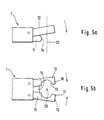
- Fig. 5a, 5b
- in einer Seitenansicht (Fig. 5a) beziehungsweise Draufsicht (Fig. 5b) zwei verschiedene Ausgestaltungen des Prinzipes des erfindungsgemäßen Greifers.
- 1, 2
- The tool magazine system according to the invention in a perspective representation (FIG. 1) and in a side view (FIG. 2),
- Fig. 3
- a perspective view of two grippers according to the invention in the gripping system also according to the invention,
- Fig. 4
- in a plan view a detail of the gripper and
- 5a, 5b
- in a side view (Fig. 5a) or plan view (Fig. 5b) two different configurations of the principle of the gripper according to the invention.
In Fig. 1, 2 ist das erfindungsgemäße Werkzeugmagazinsystem
schematisch dargestellt. In einem Werkzeugmagazin 3 sind die
Werkzeuge 2 gelagert und werden durch einen Greifer 1 bei Bedarf
ergriffen. Das Werkzeugmagazin 3 besteht dabei zum Beispiel
aus einem Werkzeugregal mit mehreren Regalböden 30 übereinander.
Die Regalböden 30 weisen hierbei einen senkrechten
Rücken 33 auf, an dem die Böden an einer nicht weiter dargestellte
Trägerwand oder Trägerrahmen oder dergleichen befestigbar
sind. Der im Wesentlichen rechtwinklig zum Rücken 33 vorstehende
Werkzeugträger 34 weist an seiner vorderen, dem Rücken
abgewandten Seite, Ausnehmungen 31 auf, die dem Außendurchmesser
des aufzunehmenden Werkzeuges beziehungsweise Werkzeugschaftes
21 entsprechen und die Lagervorrichtung 31 bilden. In
dem Werkzeugträger 34 sind im Bereich der Ausnehmungen entsprechende
Absätze hierfür angeformt.1, 2 is the tool magazine system according to the invention
shown schematically. In a
Über dem Werkzeug 2 ist ein Tropfblech 32 angeordnet um zu
vermeiden, daß von einem noch nassen Werkzeug 2, welches eingeliefert
wird, Kühlflüssigkeit auf ein darunterliegendes Werkzeug
heruntertropft und dieses insbesondere an den sensitiven
Funktionalflächen oder Aufnahmeflächen (HSK-Schaft oder Steilkegelschaft)
verschmutzt.A
Durch die erfindungsgemäße Ausgestaltung wird erreicht, daß die
Regalböden 30 im Wesentlichen übereinander angeordnet sind und
daher das gesamte Werkzeugmagazinsystem verhältnismäßig
flächensparend realisierbar ist.The configuration of the invention ensures that the
In Fig. 1, 2, unteres Werkzeugmagazin 3, ist der Einsatz des
erfindungsgemäßen Greifers gezeigt. Bezüglich der Längsachse
beziehungsweise Rotationsachse 20 wird der Greifer 1 rechtwinklig
an das Werkzeug 2 herangeführt. Der Greifer 1 wird durch
ein nicht weiter dargestelltes Handhabungsgerät entlang aller
Raumachsen und bezüglich einer Mehrzahl von Drehachsen geführt/
bewegt und weist zwei Teile 11 und 12 auf.In Fig. 1, 2,
Die genaue Ausgestaltung des Greifers 1 ergibt sich insbesondere
aus Fig. 3 und 4.The exact design of the
In Fig. 3 ist insbesondere das Umgreifen des Werkzeuges 2 mit
zwei im Wesentlichen identisch ausgebildeten Greifern 10, 19
gezeigt. Zunächst soll aber auf das Ergreifen des Werkzeuges 2
durch den Greifer 1 im einzelnen eingegangen werden.In Fig. 3, the gripping of the
Der Greifer 1, 10 besteht, wie bereits geschildet, aus einem
Greifarm 16, der an seinem vorderen Ende zwei Teile, nämlich
ein erstes Teil 11 und ein zweites Teil 12 aufweist. Die zwei
Teile 11 und 12 wirken derart zusammen, daß das Werkzeug 2
sicher gehalten wird.The
In dem hier dargestellten Ausführungsbeispiel ist das zweite
Teil 12 um eine rechtwinklig zur Längsachse 20 orientierte,
üblicherweise horizontal angeordnete Schwenkachse schwenkbar,
also beweglich gelagert, wohingegen das erste Teil 11 am Greifarm
16 feststehend ausgebildet ist. Das erste Teil 11 weist
mindestens eine Anlagefläche 14, 14' auf (Fig. 4). Diese
Anlagefläche 14 ist federartig, prismatisch ausgebildet und
entspricht in ihrer Kontur der Ausformung der Umfangsrille 22
an dem Werkzeugschaft 21 beziehungsweise dem Werkzeug 2. Diese
Umfangsrille 22 ist im Bereich der Ausgestaltung der Werkzeuge,
gerade für spanabhebende Werkzeuge weit verbreitet und als
Standard üblich. Durch das Eintauchen der Anlagefläche 14 in
die Rille 22 wird das Werkzeug im Hinblick auf den Greifer 1
axial zur Längsachse 20 festgelegt. Es verbleibt somit noch
eine Bewegung in der radialen Ebene, diese Freiheitsgrade
werden durch das Zusammenwirken des zweiten Teiles 12 mit dem
Werkzeug 2 eliminiert. An dem zweiten Teil 12 sind hierzu zwei
Anlageflächen 13, 13' vorgesehen, wobei sich das Werkzeug im
Greifer zwischen diesen Anlageflächen befindet und gegebenenfalls
auch klemmend gehalten ist.In the embodiment shown here is the
Hierbei ist es von Vorteil, daß der Schaft 21, an welchem das
zweite Teil anliegt, einen größeren Durchmesser oder Außenabmessungen
aufweist, wie der Rest des Werkzeuges 2, um bei der
klauenartigen Ausgestaltung des zweiten Teiles 12 sicherzustellen,
daß die Klaue über den Halbdurchmesser des Werkzeugschaftes
21 greift. Dabei wird das zweite Teil 12 im Bereich
des schmäleren Durchmessers über die Werkzeugachse bewegt und
dann in einer Bewegungskomponente in Richtung der Längsachse
des Werkzeuges auf den Schaft geschwenkt. Als Halbdurchmesser
wird hierbei die Strecke beschrieben, die überwunden werden
muß, um die äußeren Bereiche des klauenartigen Teiles 12 hinter
den maximalen Außendurchmesser des Schaftes/des Werkzeuges zu
positionieren. Um dies zu erreichen ist ein zum Beispiel
zylindrischer Werkzeugschaft mindestens dem Halbdurchmesser
entsprechend in eine entsprechende Aufnahme hineinzubewegen,
um ein Hintergreifen des Zylinders in der Klaue zu ermöglichen.It is advantageous here that the
Das Zusammenwirken der Anlageflächen 13, 13' des zweiten Teiles
12 ist insbesondere in Fig. 4 gezeigt, welches eine Unteransicht
des erfindungsgemäßen Greifers 1 darstellt. In einer
Klappbewegung wird das zweite Teil 12 beim Ergreifen des Werkzeuges
in Richtung auf den ersten Teil 11 bewegt und so das
Werkzeug 2 axial und radial im Greifer festgelegt. Die Anlageflächen
13, 13' befinden sich dabei in einem Umfangsabstand von
weniger als 180° auf der der Klauenöffnung zugewandten Seite
des Teiles 12, um im Zusammenwirken mit der Anschlagfläche 14
des ersten Teiles 11 die beiden verbliebenen Freiheitsgrade der
flächigen Bewegungsmöglichkeit in radialer Beweglichkeit zu
eliminieren.The interaction of the contact surfaces 13, 13 'of the
In der in Fig. 3 beziehungsweise 4 dargestellten Ausgestaltung
ist auf dem zweiten Teil 12 eine Abdeckung 100 vorgesehen, die
aber auf ihrer Unterseite mit dem Werkzeug nicht zwingend in
Berührung zu kommen hat um den Halteeffekt zu erreichen. Auf
die Abdeckung 100 kann auch verzichtet werden.In the embodiment shown in Fig. 3 or 4
a
Es ist dabei ein großer Vorteil der Erfindung, daß das Ergreifen
des Werkzeuges 2 radial bezüglich der Längsachse 20 erfolgt.
Für das Festhalten des Werkzeuges 2 sind dabei die Ausnutzung
von Absätzen, Längsnuten und so weiter, die bei dem
Werkzeugschaft 21 sonst auch vorgesehen sind, nicht notwendig.
Insbesondere werden die Funktionalflächen 23, die eine genaue
Lage und Positionierung des Werkzeuges 2 in der Arbeitsspindel
beziehungsweise bezüglich des Werkstückes definieren, für das
Greifen nicht benötigt, wodurch diese Flächen während des
Transportes frei sind um zum Beispiel gereinigt zu werden.It is a great advantage of the invention that the gripping
of the
Hierfür ist auch vorgesehen, daß zwischen der Abdeckung 100 und
der Funktionalfläche 23 ein Spalt besteht, das heißt, die Innenfläche
der Abdeckung 100 nicht direkt auf der Funktionalfläche
23 aufliegt.For this purpose it is also provided that between the
Durch diese Ausgestaltung wird erreicht, daß die Funktionalfläche nicht beschädigt wird und auch jederzeit gereinigt werden kann. This configuration ensures that the functional surface is not damaged and also cleaned at any time can be.
In Fig. 4 ist gezeigt, daß zwei Anlageflächen 14, 14' an dem
ersten, hier feststehend ausgebildeten ersten Teil 11 angeordnet
sind, die in einem Umfangsabstand von ca. 60° bis 90° sich
auf einem Umfangswinkel von ca. 30° erstreckt. Dadurch wird
eine sicher Lagerung des Werkzeuges 2 erreicht. Für eine
radiale Ausrichtung oder Lagesicherung ist an dem ersten Teil
11 auch eine Lagesicherung 15 zum Beispiel in Form eines Nutsteines
vorgesehen, der in eine entsprechende Ausnehmung an dem
Werkzeug eingreift.In Fig. 4 it is shown that two
Die Anlageflächen 13, 13' an dem zweiten Teil 12 sind in der
Regel exakt bearbeitet und erlauben eine formschlüssige, klemmende
Anlage des vorderen Bereiches des zweiten Teiles 12 an
dem Werkzeugschaft 21. Die Anlagefläche 13, 13' erstreckt sich
hierbei auch ca. über einen angulären Bereich von ca. 15° bis
30°. Alternativ braucht hier keine Klemmung vorgesehen werden,
sondern es reicht unter Umständen auch eine im Wesentlichen
spielfreie Anlage aus.The contact surfaces 13, 13 'on the
In Fig. 5b ist gezeigt, daß das erfindungsgemäße Prinzip nicht
nur als Klappenprinzip (Fig. 5a, beziehungsweise Fig. 3 und 4)
realisierbar ist, sondern auch mit dem Prinzip einer Zange
verwirklichbar ist. Hierzu besteht das zweite Teil 12 aus zwei
Elementen 17, 18, die klauen- oder zangenartig zusammenwirken.
Sie sind hierzu um Drehpunkte gelenkig gelagert und mit entsprechenden
Antrieben ausgestattet. In dem in Fig. 5b gezeigten
Prinzip befindet sich das erste Teil 11 unterhalb der Elemente
des zweiten Teiles 12. Die Achse 20 des Werkzeuges 2 ist mit
einem Kreuz angedeutet, das Werkzeug 2 ist im Übrigen nicht
gezeigt.5b shows that the principle according to the invention is not
only as a flap principle (Fig. 5a, or Fig. 3 and 4)
is feasible, but also with the principle of pliers
is feasible. For this purpose, the
Erfindungsgemäß wird vorgeschlagen, daß das erste und zweite
Teil 11, 12 zueinander relativ beweglich ist. Hierfür ist ein
Antrieb vorgesehen, der zum Beispiel als hydraulischer oder
pneumatischer Arbeitszylinder, der in den Greifarm 16 integriert
ist, ausgebildet ist oder zum Beispiel als Elektromotor
realisiert ist. Es ist so möglich, eine Fremdbetätigung als
Antrieb vorzusehen, das heißt, die Bewegung des Greifers auf
seinem Handhabungsgerät derart auszunützen, daß der Greifer an
entsprechende Anschläge geführt wird und dann, aufgrund des
Antriebes des Greifers, die Teile 11, 12 bewegt werden. Dabei
kann die Fremdbetätigung auch durch den zweiten Greifer oder
durch andere Elementen an der Werkzeugmaschine und so weiter
erfolgen.According to the invention it is proposed that the first and
Des Weiteren ist vorgesehen, daß die zueinander beweglichen
Teile 11, 12 oder Elemente 17, 18 des zweiten Teiles 12 zueinander
fixierbar sind. Hierzu sind zum Beispiel Keilsysteme,
Bolzen oder dergleichen vorgesehen, um einen sicheren Halt des
Werkzeuges 2 im Greifer 1 zu erreichen. Die Fixierung kann aber
auch durch entsprechend ausgebildete Arbeitszylinder und so
weiter erfolgen.Furthermore, it is provided that the mutually
Des Weiteren ist es günstig, wenn die zueinander beweglichen
Teile 11, 12 beziehungsweise Elemente 17, 18 eine Zuhaltung
aufweisen. Die Zuhaltung wird zum Beispiel ebenfalls durch
einen hydraulisch oder pneumatisch wirkenden Arbeitszylinder
bewirkt. Es können aber auch entsprechende Federn (Druck-, Zug-
oder Tellerfedern) vorgesehen werden, die entgegen der Wirkrichtung
des Arbeitszylinders angeordnet sind. Wird der Arbeitszylinder
oder der Antrieb nicht beaufschlagt, so wirkt die
Kraft dieser passiven Elemente, zum Beispiel der Feder, als
Zuhaltung. Im Fall, daß eine entgegengesetzte Bewegung gewünscht
wird, muß der Arbeitszylinder eine entsprechend große
Kraft aufwenden, um die Kraft der Zuhaltung zu überwinden.Furthermore, it is advantageous if the mutually
Beim Ergreifen des Werkzeuges 2 taucht zunächst die Anlagefläche
14, 14' des ersten Teiles 11 in die Umfangsrille 22 des
Werkzeugschaftes 21 ein. Anstelle der Umfangsrille ist es auch
möglich, daß eine Ringnut, Rille, Vertiefung oder ein Absatz
beziehungsweise eine Haltenase und so weiter an dem Werkzeug 2
und/oder auch an dem Werkzeugschaft 21 vorgesehen ist. Vorher,
gleichzeitig oder hernach wird das zweite Teil klemmend an den
Werkzeugschaft 21 oder das Werkzeug 2 herangeführt, wobei das
zweite Teil 12 an dessen Mantelfläche angreift. Wie in Fig. 5a
gezeigt, bewegt sich hierbei das zweite Teil 12 auf das erste
Teil 11 zu, wobei das zweite Teil 12 hierbei eine Schwenkbewegung
beschreibt, dessen Bewegung in dem spitzen Winkel oder
fast parallel zur Längsachse 20 orientiert ist. Beim Lösen
beziehungsweise Loslassen des Werkzeuges zum Beispiel wird der
vorbeschriebene Ablauf umgedreht, wobei sich zunächst das
zweite Teil 12 vom Schaft 21 beziehungsweise Werkstück 2 entfernt
und die Klemmung überwindet, indem das erste Teil 11 in
seinem Zusammenwirken mit dem Werkzeug 2 beziehungsweise dem
Werkzeugschaft 21 ein Wiederlager hierzu bildet. Die Klemmung
wird dabei in einer Bewegung in axialer Richtung überwunden,
wobei die axiale Festlegung des Werkzeuges durch das erste Teil
als Wiederlage ausgenützt wird.When gripping
Bei dem in Fig. 5a dargestellten Prinzip bewegt sich zwar das
zweite Teil 12 abschnittsweise in Längsrichtung also parallel
zur Längsachse 20, wobei aber nur ein Teil 12 des Greifers 1
bewegt wird. Der Greifer 1 im Ganzen wird seitlich, zum Beispiel
im Wesentlichen rechtwinklig zur Längsachse 20 an das
Werkzeug herangeführt und erlaubt daher insbesondere die vertikale
Anordnung von vielen Werkzeugen übereinander. Durch die
vorgeschlagene Bewegung des Teiles 12 wird erreicht, daß das
Teil 12 in einen Bereich über das Werkzeug geschoben wird, in
welchem der Durchmesser geringer ist, da die klauenartige Ausbildung
des zweiten Teiles 12 das komplette Werkzeug umgreifen
soll. Das Teil 12 wird daher so positioniert, daß es in dem
schmäleren Bereich das Werkzeug übergreift und dann spitzwinklig
oder im Wesentlichen parallel zur Längsachse auf den Schaft
aufgeführt und klemmend daran festgelegt wird. In the principle shown in Fig. 5a, this moves
Auf eine vertikale Komponente beziehungsweise eine Komponente
parallel zur Längsachse 20 des zweiten Teiles 12 wird bei dem
Vorschlag nach 5b verzichtet, da hier eine Zangen- oder Klauenbewegung
der beiden beweglich zueinander ausgestalteten Elemente
17 und 18 vorgesehen ist. Die Bewegung der Elemente 17,
18, beide gemeinsam oder jeweils nur einzeln bewegt, erfolgt
hierbei in einer Ebene, die rechtwinklig ist zur Längsachse 20.A vertical component or a component
parallel to the
In Fig. 4 ist ein erfindungsgemäßes Umgreifsystem für das Umgreifen
eines Gegenstandes zum Beispiel des Werkzeuges 2 gezeigt.
Das Umgreifsystem besteht hierbei aus zwei Greifern 10,
19, die identisch aufgebaut sind. Auf die Identität der beiden
Greifer kommt es bei dem Einsatz der Erfindung aber nicht an.
Die beiden Greifer 10, 19 sind dabei so angeordnet, daß sie
bezüglich einer Achse rechtwinklig zur Werkzeuglängsachse 20
gedreht am Werkzeug auf unterschiedlichen Seiten angreifen.4 is a gripping system according to the invention for gripping
an object, for example the
Wie in Fig. 3 ersichtlich, ist die Ausgestaltung insbesondere
des ersten Teiles 11, 11' so gewählt, daß diese bei gegenüberliegenden
Eingriff an dem Werkzeug einen Spalt zwischen sich
bilden, das heißt, das erste Teil 11 umgreift nicht den kompletten
Halbkreis des Werkzeugschaftes 21. Das zweite Teil 12,
12' jedoch übergreift aber die breiteste Stelle des Durchmesser
des Werkzeuges 2 beziehungsweise Werkzeugschaftes 21, allerdings
jeweil auf gegensätzlichen Seiten des Schaftes bezüglich
der Rille 22. Durch die verdrehte Anordnung kollidieren die
beiden Seitenteile 12, 12' nicht, da sie auf bezüglich der
Rille 22 unterschiedlichen Schaftabschnitten angreifen.As can be seen in FIG. 3, the configuration is special
of the
Die jetzt mit der Anmeldung und später eingereichten Ansprüche sind Versuche zur Formulierung ohne Präjudiz für die Erzielung weitergehenden Schutzes.The claims now filed with the application and later are attempts to formulate without prejudice to achieve further protection.
Die in den abhängigen Ansprüchen angeführten Rückbeziehungen weisen auf die weitere Ausbildung des Gegenstandes des Hauptanspruches durch die Merkmale des jeweiligen Unteranspruches hin. Jedoch sind diese nicht als ein Verzicht auf die Erzielung eines selbständigen, gegenständlichen Schutzes für die Merkmale der rückbezogenen Unteransprüche zu verstehen.The backward relations mentioned in the dependent claims point to the further training of the subject of the main claim by the features of the respective subclaim out. However, these are not considered a waiver of achievement an independent, objective protection for the characteristics to understand the related subclaims.
Merkmale, die bislang nur in der Beschreibung offenbart wurden, können im Laufe des Verfahrens als von erfindungswesentlicher Bedeutung, zum Beispiel zur Abgrenzung vom Stand der Technik beansprucht werden.Features previously only disclosed in the description can in the course of the process as of essential to the invention Significance, for example to differentiate it from the prior art be claimed.
Claims (24)
Applications Claiming Priority (2)
| Application Number | Priority Date | Filing Date | Title |
|---|---|---|---|
| DE10039525 | 2000-08-08 | ||
| DE10039525A DE10039525A1 (en) | 2000-08-08 | 2000-08-08 | Machine tool with gripper and or tool magazine system |
Publications (2)
| Publication Number | Publication Date |
|---|---|
| EP1179387A1 true EP1179387A1 (en) | 2002-02-13 |
| EP1179387B1 EP1179387B1 (en) | 2004-04-28 |
Family
ID=7652281
Family Applications (1)
| Application Number | Title | Priority Date | Filing Date |
|---|---|---|---|
| EP01117517A Expired - Lifetime EP1179387B1 (en) | 2000-08-08 | 2001-07-20 | Machine tool provided with a gripper and/or tool magazine system |
Country Status (6)
| Country | Link |
|---|---|
| US (2) | US6783484B2 (en) |
| EP (1) | EP1179387B1 (en) |
| AT (1) | ATE265289T1 (en) |
| DE (2) | DE10039525A1 (en) |
| ES (1) | ES2219463T3 (en) |
| PT (1) | PT1179387E (en) |
Cited By (3)
| Publication number | Priority date | Publication date | Assignee | Title |
|---|---|---|---|---|
| EP1607175A2 (en) * | 2004-06-14 | 2005-12-21 | Chiron-Werke GmbH & Co. KG | Carrier for a toolholder |
| EP2900418B1 (en) * | 2012-09-26 | 2018-12-05 | Chiron-Werke GmbH & Co. KG | Worktool gripper for a worktool holder, worktool magazine and machine tool |
| US11919107B2 (en) | 2018-09-06 | 2024-03-05 | Yamazaki Mazak Corporation | Tool storage, machine tool, hybrid working machine |
Families Citing this family (6)
| Publication number | Priority date | Publication date | Assignee | Title |
|---|---|---|---|---|
| GB0207298D0 (en) * | 2002-03-28 | 2002-05-08 | Renishaw Plc | Apparatus for changing operating modules on a coordinate positioning machine |
| US8221297B2 (en) * | 2007-01-26 | 2012-07-17 | Faust Solutions Ltd. | Storage system for tool holders |
| GB0717969D0 (en) * | 2007-09-14 | 2007-10-24 | Renishaw Plc | Module changing for modular probe |
| US8574139B2 (en) * | 2009-08-12 | 2013-11-05 | Microlution, Inc. | Machine tool with automatic tool changer |
| DE102012102571A1 (en) | 2012-03-26 | 2013-09-26 | Chiron-Werke Gmbh & Co Kg | Tool carrier for a tool holder |
| EP3351204A1 (en) | 2017-01-24 | 2018-07-25 | Martin Huber | Dental milling machine |
Citations (11)
| Publication number | Priority date | Publication date | Assignee | Title |
|---|---|---|---|---|
| US4238034A (en) * | 1979-04-16 | 1980-12-09 | Kearney & Trecker Corporation | Automatic tool changer for machine tool |
| DE3440604A1 (en) * | 1984-11-07 | 1986-05-07 | Werkzeugmaschinenfabrik Adolf Waldrich Coburg Gmbh & Co, 8630 Coburg | Automatic tool-changing device for machine tools, especially for universal machining centres |
| US4827599A (en) * | 1988-08-10 | 1989-05-09 | Chiron-Werke Gmbh & Co. Kg | Machine tool |
| EP0355271A2 (en) * | 1988-08-23 | 1990-02-28 | Cincinnati Milacron Inc. | Article gripper |
| EP0585471A1 (en) * | 1992-03-19 | 1994-03-09 | Fanuc Ltd. | Tool holder gripper |
| EP0623419A2 (en) * | 1993-05-07 | 1994-11-09 | Niigata Engineering Co., Ltd. | Automatic tool exchanger |
| US5372568A (en) * | 1992-06-18 | 1994-12-13 | Brother Kogyo Kabushiki Kaisha | Machine tool with automatic tool changer, having mechanism for utilizing relative movements of tool and tool changing gripper to clamp and unclamp the tool |
| US5383832A (en) * | 1993-04-07 | 1995-01-24 | Stama Mashinenfabrik, Gmbh | Method and machine for performing a tool change |
| JPH08257862A (en) * | 1995-03-27 | 1996-10-08 | Okuma Mach Works Ltd | Tool gripper |
| JP2000141155A (en) * | 1998-11-13 | 2000-05-23 | Toshiba Mach Co Ltd | Tool exchange device |
| JP2000343367A (en) * | 1999-06-02 | 2000-12-12 | Mori Machinery Corp | Tool carry-in and out storage device of rack type tool magazine |
Family Cites Families (19)
| Publication number | Priority date | Publication date | Assignee | Title |
|---|---|---|---|---|
| GB1355345A (en) * | 1970-08-14 | 1974-06-05 | Doall Co | Machine for exchanging tools in a machine tool |
| BG18462A1 (en) * | 1973-02-09 | 1975-02-25 | ||
| US3953039A (en) * | 1974-08-30 | 1976-04-27 | Textron Inc. | Toolholder for machine tools |
| US4041601A (en) * | 1976-03-12 | 1977-08-16 | Wells Manufacturing Corporation | Machine tool with an automatic tool changer |
| US4335498A (en) * | 1979-03-08 | 1982-06-22 | Textron, Inc. | Machine tool |
| DE3320762C2 (en) * | 1983-06-09 | 1994-10-27 | Trumpf Gmbh & Co | Punching machine with a stationary magazine |
| US4604787A (en) * | 1984-08-15 | 1986-08-12 | Transamerica Delaval Inc. | Tool changer for manipulator arm |
| DE3763931D1 (en) * | 1986-07-29 | 1990-08-30 | Maho Ag | TOOL CHANGER FOR UNIVERSAL MILLING AND DRILLING MACHINES. |
| DE3717201A1 (en) * | 1987-05-22 | 1988-12-08 | Chiron Werke Gmbh | GRIPPER FOR TOOLS OF A MACHINE TOOL |
| DE3812026A1 (en) * | 1987-06-25 | 1989-01-05 | Szerszamgepipari Muevek | Tool-shank gripper for automatic tool change in machine tools |
| DE3742096A1 (en) * | 1987-12-11 | 1989-06-22 | Wanderer Maschinen Gmbh | TOOL MAGAZINE |
| US5172951A (en) * | 1990-08-06 | 1992-12-22 | University Of Utah Research Foundation | Robotic grasping apparatus |
| DE4036914C2 (en) * | 1990-11-20 | 1994-02-10 | Chiron Werke Gmbh | Tool changer for tools of a machine tool |
| DE4036915A1 (en) * | 1990-11-20 | 1992-05-21 | Chiron Werke Gmbh | MACHINE TOOL AND METHOD FOR OPENING AND CLOSING A GRIPPER |
| JP2761813B2 (en) * | 1991-03-25 | 1998-06-04 | オークマ株式会社 | Tool delivery device |
| DE69424401T2 (en) * | 1993-09-10 | 2000-12-21 | Charmilles Technologies | Magazine for changing tools or workpieces in machine tools |
| JP3012463B2 (en) * | 1993-12-22 | 2000-02-21 | 松下電工株式会社 | Assembly equipment |
| JP3035195B2 (en) * | 1995-08-11 | 2000-04-17 | キタムラ機械株式会社 | Spindle device |
| US5672145A (en) * | 1996-06-27 | 1997-09-30 | Bridgeport Machines Inc. | Tool carousel |
-
2000
- 2000-08-08 DE DE10039525A patent/DE10039525A1/en not_active Withdrawn
-
2001
- 2001-07-20 ES ES01117517T patent/ES2219463T3/en not_active Expired - Lifetime
- 2001-07-20 PT PT01117517T patent/PT1179387E/en unknown
- 2001-07-20 DE DE50102105T patent/DE50102105D1/en not_active Expired - Lifetime
- 2001-07-20 EP EP01117517A patent/EP1179387B1/en not_active Expired - Lifetime
- 2001-07-20 AT AT01117517T patent/ATE265289T1/en active
- 2001-08-01 US US09/918,457 patent/US6783484B2/en not_active Expired - Fee Related
-
2004
- 2004-08-18 US US10/920,242 patent/US7175579B2/en not_active Expired - Lifetime
Patent Citations (11)
| Publication number | Priority date | Publication date | Assignee | Title |
|---|---|---|---|---|
| US4238034A (en) * | 1979-04-16 | 1980-12-09 | Kearney & Trecker Corporation | Automatic tool changer for machine tool |
| DE3440604A1 (en) * | 1984-11-07 | 1986-05-07 | Werkzeugmaschinenfabrik Adolf Waldrich Coburg Gmbh & Co, 8630 Coburg | Automatic tool-changing device for machine tools, especially for universal machining centres |
| US4827599A (en) * | 1988-08-10 | 1989-05-09 | Chiron-Werke Gmbh & Co. Kg | Machine tool |
| EP0355271A2 (en) * | 1988-08-23 | 1990-02-28 | Cincinnati Milacron Inc. | Article gripper |
| EP0585471A1 (en) * | 1992-03-19 | 1994-03-09 | Fanuc Ltd. | Tool holder gripper |
| US5372568A (en) * | 1992-06-18 | 1994-12-13 | Brother Kogyo Kabushiki Kaisha | Machine tool with automatic tool changer, having mechanism for utilizing relative movements of tool and tool changing gripper to clamp and unclamp the tool |
| US5383832A (en) * | 1993-04-07 | 1995-01-24 | Stama Mashinenfabrik, Gmbh | Method and machine for performing a tool change |
| EP0623419A2 (en) * | 1993-05-07 | 1994-11-09 | Niigata Engineering Co., Ltd. | Automatic tool exchanger |
| JPH08257862A (en) * | 1995-03-27 | 1996-10-08 | Okuma Mach Works Ltd | Tool gripper |
| JP2000141155A (en) * | 1998-11-13 | 2000-05-23 | Toshiba Mach Co Ltd | Tool exchange device |
| JP2000343367A (en) * | 1999-06-02 | 2000-12-12 | Mori Machinery Corp | Tool carry-in and out storage device of rack type tool magazine |
Non-Patent Citations (3)
| Title |
|---|
| PATENT ABSTRACTS OF JAPAN vol. 1997, no. 02 28 February 1997 (1997-02-28) * |
| PATENT ABSTRACTS OF JAPAN vol. 2000, no. 08 6 October 2000 (2000-10-06) * |
| PATENT ABSTRACTS OF JAPAN vol. 2000, no. 15 6 April 2001 (2001-04-06) * |
Cited By (5)
| Publication number | Priority date | Publication date | Assignee | Title |
|---|---|---|---|---|
| EP1607175A2 (en) * | 2004-06-14 | 2005-12-21 | Chiron-Werke GmbH & Co. KG | Carrier for a toolholder |
| EP1607175A3 (en) * | 2004-06-14 | 2006-02-15 | Chiron-Werke GmbH & Co. KG | Carrier for a toolholder |
| US7255667B2 (en) | 2004-06-14 | 2007-08-14 | Chiron-Werke Gmbh & Co. Kg | Carrier for tool holders |
| EP2900418B1 (en) * | 2012-09-26 | 2018-12-05 | Chiron-Werke GmbH & Co. KG | Worktool gripper for a worktool holder, worktool magazine and machine tool |
| US11919107B2 (en) | 2018-09-06 | 2024-03-05 | Yamazaki Mazak Corporation | Tool storage, machine tool, hybrid working machine |
Also Published As
| Publication number | Publication date |
|---|---|
| EP1179387B1 (en) | 2004-04-28 |
| DE10039525A1 (en) | 2002-02-21 |
| PT1179387E (en) | 2004-09-30 |
| US6783484B2 (en) | 2004-08-31 |
| US20020028735A1 (en) | 2002-03-07 |
| US7175579B2 (en) | 2007-02-13 |
| ES2219463T3 (en) | 2004-12-01 |
| DE50102105D1 (en) | 2004-06-03 |
| ATE265289T1 (en) | 2004-05-15 |
| US20050020420A1 (en) | 2005-01-27 |
Similar Documents
| Publication | Publication Date | Title |
|---|---|---|
| EP0216261B1 (en) | Machine tool | |
| EP1616661B1 (en) | Machine tool with workpiece changing device | |
| EP1004393B1 (en) | Machine tool arrangment with a device for automatic tool-change | |
| WO2010012017A1 (en) | Machine tool | |
| EP0885686A1 (en) | Machining centre | |
| EP2881219B1 (en) | Tool exchange apparatus for use in a machining centre and machining centre for machining a workpiece | |
| EP1752255B1 (en) | Multispindle lathe with articulated workpiece manipulator | |
| EP1179387A1 (en) | Machine tool provided with a gripper and/or tool magazine system | |
| EP1752241B1 (en) | Turning machine | |
| DE3519754C2 (en) | ||
| EP0824389B1 (en) | Device for use in electrical discharge machining of work pieces | |
| DE10200709A1 (en) | Processing system for processing workpieces comprises a first machine tool assembly, a second machine tool assembly, and a support unit | |
| EP3664959B1 (en) | Method and device for furnishing screws | |
| DE102019100257A1 (en) | Machine tool | |
| EP1289711B1 (en) | Device for gripping and transporting workpieces in turning machines | |
| EP1522381B1 (en) | Tool management system for machine tools | |
| WO2003103892A1 (en) | Multi-spindle lathe | |
| EP3031572A1 (en) | Tool exchange apparatus for use in a machining centre and machining centre for machining a workpiece | |
| DE102005006722A1 (en) | Machining plant for workpiece has tool handling device including tool grip and grip moving unit outside working cavity of machine tool | |
| EP0137117A2 (en) | Tool-changing unit having a presentation device for tool-heads | |
| DE3818564C2 (en) | ||
| EP0310811B1 (en) | Dualspindle lathe | |
| DE4009537C2 (en) | ||
| DE10334285A1 (en) | Processing machine with two processing units | |
| DE4022706C2 (en) | Lathe |
Legal Events
| Date | Code | Title | Description |
|---|---|---|---|
| PUAI | Public reference made under article 153(3) epc to a published international application that has entered the european phase |
Free format text: ORIGINAL CODE: 0009012 |
|
| AK | Designated contracting states |
Kind code of ref document: A1 Designated state(s): AT BE CH CY DE DK ES FI FR GB GR IE IT LI LU MC NL PT SE TR |
|
| AX | Request for extension of the european patent |
Free format text: AL;LT;LV;MK;RO;SI |
|
| 17P | Request for examination filed |
Effective date: 20020606 |
|
| 17Q | First examination report despatched |
Effective date: 20020801 |
|
| AKX | Designation fees paid |
Free format text: AT BE CH CY DE DK ES FI FR GB GR IE IT LI LU MC NL PT SE TR |
|
| GRAP | Despatch of communication of intention to grant a patent |
Free format text: ORIGINAL CODE: EPIDOSNIGR1 |
|
| GRAA | (expected) grant |
Free format text: ORIGINAL CODE: 0009210 |
|
| GRAS | Grant fee paid |
Free format text: ORIGINAL CODE: EPIDOSNIGR3 |
|
| AK | Designated contracting states |
Kind code of ref document: B1 Designated state(s): AT BE CH CY DE DK ES FI FR GB GR IE IT LI LU MC NL PT SE TR |
|
| PG25 | Lapsed in a contracting state [announced via postgrant information from national office to epo] |
Ref country code: TR Free format text: LAPSE BECAUSE OF FAILURE TO SUBMIT A TRANSLATION OF THE DESCRIPTION OR TO PAY THE FEE WITHIN THE PRESCRIBED TIME-LIMIT Effective date: 20040428 Ref country code: FI Free format text: LAPSE BECAUSE OF FAILURE TO SUBMIT A TRANSLATION OF THE DESCRIPTION OR TO PAY THE FEE WITHIN THE PRESCRIBED TIME-LIMIT Effective date: 20040428 Ref country code: NL Free format text: LAPSE BECAUSE OF FAILURE TO SUBMIT A TRANSLATION OF THE DESCRIPTION OR TO PAY THE FEE WITHIN THE PRESCRIBED TIME-LIMIT Effective date: 20040428 Ref country code: IE Free format text: LAPSE BECAUSE OF FAILURE TO SUBMIT A TRANSLATION OF THE DESCRIPTION OR TO PAY THE FEE WITHIN THE PRESCRIBED TIME-LIMIT Effective date: 20040428 Ref country code: CY Free format text: LAPSE BECAUSE OF FAILURE TO SUBMIT A TRANSLATION OF THE DESCRIPTION OR TO PAY THE FEE WITHIN THE PRESCRIBED TIME-LIMIT Effective date: 20040428 |
|
| REG | Reference to a national code |
Ref country code: GB Ref legal event code: FG4D Free format text: NOT ENGLISH |
|
| REG | Reference to a national code |
Ref country code: CH Ref legal event code: EP |
|
| REG | Reference to a national code |
Ref country code: IE Ref legal event code: FG4D Free format text: GERMAN |
|
| REF | Corresponds to: |
Ref document number: 50102105 Country of ref document: DE Date of ref document: 20040603 Kind code of ref document: P |
|
| PG25 | Lapsed in a contracting state [announced via postgrant information from national office to epo] |
Ref country code: LU Free format text: LAPSE BECAUSE OF NON-PAYMENT OF DUE FEES Effective date: 20040720 |
|
| REG | Reference to a national code |
Ref country code: SE Ref legal event code: TRGR |
|
| GBT | Gb: translation of ep patent filed (gb section 77(6)(a)/1977) |
Effective date: 20040628 |
|
| PG25 | Lapsed in a contracting state [announced via postgrant information from national office to epo] |
Ref country code: DK Free format text: LAPSE BECAUSE OF FAILURE TO SUBMIT A TRANSLATION OF THE DESCRIPTION OR TO PAY THE FEE WITHIN THE PRESCRIBED TIME-LIMIT Effective date: 20040728 Ref country code: GR Free format text: LAPSE BECAUSE OF FAILURE TO SUBMIT A TRANSLATION OF THE DESCRIPTION OR TO PAY THE FEE WITHIN THE PRESCRIBED TIME-LIMIT Effective date: 20040728 |
|
| PG25 | Lapsed in a contracting state [announced via postgrant information from national office to epo] |
Ref country code: BE Free format text: LAPSE BECAUSE OF NON-PAYMENT OF DUE FEES Effective date: 20040731 Ref country code: MC Free format text: LAPSE BECAUSE OF NON-PAYMENT OF DUE FEES Effective date: 20040731 |
|
| REG | Reference to a national code |
Ref country code: PT Ref legal event code: SC4A Free format text: AVAILABILITY OF NATIONAL TRANSLATION Effective date: 20040722 |
|
| NLV1 | Nl: lapsed or annulled due to failure to fulfill the requirements of art. 29p and 29m of the patents act | ||
| REG | Reference to a national code |
Ref country code: IE Ref legal event code: FD4D Ref country code: ES Ref legal event code: FG2A Ref document number: 2219463 Country of ref document: ES Kind code of ref document: T3 |
|
| ET | Fr: translation filed | ||
| BERE | Be: lapsed |
Owner name: GROB-WERKE DR. H.C. MULT. DIPL.-ING. BURKHART GROB Effective date: 20040731 |
|
| PLBE | No opposition filed within time limit |
Free format text: ORIGINAL CODE: 0009261 |
|
| STAA | Information on the status of an ep patent application or granted ep patent |
Free format text: STATUS: NO OPPOSITION FILED WITHIN TIME LIMIT |
|
| 26N | No opposition filed |
Effective date: 20050131 |
|
| PGFP | Annual fee paid to national office [announced via postgrant information from national office to epo] |
Ref country code: GB Payment date: 20050707 Year of fee payment: 5 |
|
| PGFP | Annual fee paid to national office [announced via postgrant information from national office to epo] |
Ref country code: PT Payment date: 20050720 Year of fee payment: 5 |
|
| PGFP | Annual fee paid to national office [announced via postgrant information from national office to epo] |
Ref country code: ES Payment date: 20050721 Year of fee payment: 5 |
|
| PG25 | Lapsed in a contracting state [announced via postgrant information from national office to epo] |
Ref country code: CH Free format text: LAPSE BECAUSE OF NON-PAYMENT OF DUE FEES Effective date: 20050731 Ref country code: LI Free format text: LAPSE BECAUSE OF NON-PAYMENT OF DUE FEES Effective date: 20050731 |
|
| REG | Reference to a national code |
Ref country code: CH Ref legal event code: PL |
|
| PG25 | Lapsed in a contracting state [announced via postgrant information from national office to epo] |
Ref country code: GB Free format text: LAPSE BECAUSE OF NON-PAYMENT OF DUE FEES Effective date: 20060720 |
|
| PG25 | Lapsed in a contracting state [announced via postgrant information from national office to epo] |
Ref country code: PT Free format text: LAPSE BECAUSE OF NON-PAYMENT OF DUE FEES Effective date: 20070122 |
|
| REG | Reference to a national code |
Ref country code: PT Ref legal event code: MM4A Free format text: LAPSE DUE TO NON-PAYMENT OF FEES Effective date: 20070122 |
|
| GBPC | Gb: european patent ceased through non-payment of renewal fee |
Effective date: 20060720 |
|
| REG | Reference to a national code |
Ref country code: ES Ref legal event code: FD2A Effective date: 20060721 |
|
| BERE | Be: lapsed |
Owner name: *GROB-WERKE BURKHART GROB E.K. Effective date: 20040731 |
|
| PG25 | Lapsed in a contracting state [announced via postgrant information from national office to epo] |
Ref country code: ES Free format text: LAPSE BECAUSE OF NON-PAYMENT OF DUE FEES Effective date: 20060721 |
|
| REG | Reference to a national code |
Ref country code: FR Ref legal event code: RM |
|
| REG | Reference to a national code |
Ref country code: FR Ref legal event code: TP |
|
| REG | Reference to a national code |
Ref country code: FR Ref legal event code: PLFP Year of fee payment: 16 |
|
| PGFP | Annual fee paid to national office [announced via postgrant information from national office to epo] |
Ref country code: SE Payment date: 20160721 Year of fee payment: 16 |
|
| REG | Reference to a national code |
Ref country code: FR Ref legal event code: PLFP Year of fee payment: 17 |
|
| REG | Reference to a national code |
Ref country code: SE Ref legal event code: EUG |
|
| PG25 | Lapsed in a contracting state [announced via postgrant information from national office to epo] |
Ref country code: SE Free format text: LAPSE BECAUSE OF NON-PAYMENT OF DUE FEES Effective date: 20170721 |
|
| REG | Reference to a national code |
Ref country code: FR Ref legal event code: PLFP Year of fee payment: 18 |
|
| REG | Reference to a national code |
Ref country code: DE Ref legal event code: R082 Ref document number: 50102105 Country of ref document: DE Representative=s name: PATENTANWAELTE OLBRICHT, BUCHHOLD, KEULERTZ PA, DE |
|
| PGFP | Annual fee paid to national office [announced via postgrant information from national office to epo] |
Ref country code: FR Payment date: 20190724 Year of fee payment: 19 Ref country code: IT Payment date: 20190723 Year of fee payment: 19 |
|
| PGFP | Annual fee paid to national office [announced via postgrant information from national office to epo] |
Ref country code: AT Payment date: 20190719 Year of fee payment: 19 |
|
| PGFP | Annual fee paid to national office [announced via postgrant information from national office to epo] |
Ref country code: DE Payment date: 20200723 Year of fee payment: 20 |
|
| REG | Reference to a national code |
Ref country code: AT Ref legal event code: MM01 Ref document number: 265289 Country of ref document: AT Kind code of ref document: T Effective date: 20200720 |
|
| PG25 | Lapsed in a contracting state [announced via postgrant information from national office to epo] |
Ref country code: FR Free format text: LAPSE BECAUSE OF NON-PAYMENT OF DUE FEES Effective date: 20200731 |
|
| PG25 | Lapsed in a contracting state [announced via postgrant information from national office to epo] |
Ref country code: AT Free format text: LAPSE BECAUSE OF NON-PAYMENT OF DUE FEES Effective date: 20200720 |
|
| REG | Reference to a national code |
Ref country code: DE Ref legal event code: R071 Ref document number: 50102105 Country of ref document: DE |
|
| PG25 | Lapsed in a contracting state [announced via postgrant information from national office to epo] |
Ref country code: IT Free format text: LAPSE BECAUSE OF NON-PAYMENT OF DUE FEES Effective date: 20200720 |