EP1177942A2 - Rückstelleinrichtung für einen Schalter eines Kraftfahrzeuges - Google Patents
Rückstelleinrichtung für einen Schalter eines Kraftfahrzeuges Download PDFInfo
- Publication number
- EP1177942A2 EP1177942A2 EP01117983A EP01117983A EP1177942A2 EP 1177942 A2 EP1177942 A2 EP 1177942A2 EP 01117983 A EP01117983 A EP 01117983A EP 01117983 A EP01117983 A EP 01117983A EP 1177942 A2 EP1177942 A2 EP 1177942A2
- Authority
- EP
- European Patent Office
- Prior art keywords
- curve
- reset device
- latching
- shift lever
- locking
- Prior art date
- Legal status (The legal status is an assumption and is not a legal conclusion. Google has not performed a legal analysis and makes no representation as to the accuracy of the status listed.)
- Granted
Links
Images


Classifications
-
- B—PERFORMING OPERATIONS; TRANSPORTING
- B60—VEHICLES IN GENERAL
- B60Q—ARRANGEMENT OF SIGNALLING OR LIGHTING DEVICES, THE MOUNTING OR SUPPORTING THEREOF OR CIRCUITS THEREFOR, FOR VEHICLES IN GENERAL
- B60Q1/00—Arrangement of optical signalling or lighting devices, the mounting or supporting thereof or circuits therefor
- B60Q1/26—Arrangement of optical signalling or lighting devices, the mounting or supporting thereof or circuits therefor the devices being primarily intended to indicate the vehicle, or parts thereof, or to give signals, to other traffic
- B60Q1/34—Arrangement of optical signalling or lighting devices, the mounting or supporting thereof or circuits therefor the devices being primarily intended to indicate the vehicle, or parts thereof, or to give signals, to other traffic for indicating change of drive direction
- B60Q1/40—Arrangement of optical signalling or lighting devices, the mounting or supporting thereof or circuits therefor the devices being primarily intended to indicate the vehicle, or parts thereof, or to give signals, to other traffic for indicating change of drive direction having mechanical, electric or electronic automatic return to inoperative position
Definitions
- the invention relates to a reset device for a switch of a motor vehicle, in particular one Turn signal switch, with a swivel-mounted, latchable Shift lever with a spring-loaded locking element, the with at least one switch position on the housing side Rest curve interacts.
- From DE-C-27 21 879 is a steering column switch with a buttoned turn signal switch known, the shift lever for the lane change flashing or for the direction indicator one to the right and one to the left one after the other two assigned pushbuttons.
- the on state the turn signal switch is operated by means of an electronic Holding device stored and by an electronic Reset device, the holding device is reset.
- the shift lever is actuated by a spring Switch bridge automatically in a neutral position reset.
- DE 197 58 288 A1 also discloses a device for resetting one with a direction of rotation Steering column interacting turn signal switch in a motor vehicle with a turn signal lever that can be swiveled around an axis of rotation, the turn signal lever in each of two, in the desired flashing position corresponding operating position is pivotable.
- a stationary backdrop is provided to guide the left turn signal lever end .
- the turn signal switch comprises two detents arranged on a detent element, that protrude beyond the backdrop contour and each hold the turn signal lever end in an operating position.
- the Locking element is movable, so that at least one detent each is flush with the backdrop contour and the in the Indicator position held released releases, with a steering column-fixed actuating element acts on the locking element and panned this.
- the turn signal switch must be in immediate Be arranged near the steering column and between the actuating element and the latching element may not additional components are located to the function of the device sure.
- DE 27 25 805 C2 is a device for switching off a direction indicator of a motor vehicle known after cornering, with stationary, magnetic field-controlled by means of a magnet attached to the steering column Donors are provided.
- These donors are Downstream electronic rotation discriminator, the depending on the signal sequence of the encoders when turning back turning off the steering wheel after cornering Direction display causes. This facility is only in connection with a buttoned turn signal switch use, since it does not interact with a catch, but only turns off the direction indicator.
- Wiper / washer switches for motor vehicles are also known, whose shift lever for the front wiper functions in and can be pivoted counterclockwise in a housing are stored and for the front / washer and rear / wiper / Washer functions are the shift levers in and against the direction of a dashboard pivoted.
- the Switch functions can be mechanically locked as well can also be executed by key.
- a computer controlled electromechanical adjustment device Latches the shift lever.
- the release of the switch is thus canceled not by means of a reset on the motor vehicle side by means of the electromechanical adjustment device that the Switch is assigned directly. Instead of complex mechanics to act on the detent between the same and the motor vehicle acts, the coupling with the Motor vehicle via the on-board computer. If the repeal of the Locking depending on the angle of rotation of a steering column should take place, as is the case, for example, with a turn signal switch is required, the switch does not have to be in immediate Arranged near the steering column and mechanically with it be coupled. Rather, the angle of rotation of the steering column captured by the on-board computer, which also sets or Not setting the switch detects. If a predetermined one Angle of rotation is reached, the on-board computer speaks the adjusting device to unlock the switch on. The on-board computer can of course also do this with Existence of other relevant data, such as at Expiration of a given period of time or certain reactions of the driver.
- the adjusting device preferably acts on the locking curve the detent and acts essentially perpendicular or parallel to a longitudinal axis of the shift lever.
- the adjustment device therefore only causes rectilinear movements of the locking curve, which are easier to implement than swivel movements, to operate the shift lever when it is reset would be required.
- the adjusting device expediently acts on the Resting curve continuously or by means of an impulse. If to cancel the locking the locking curve only one relative a short impulse is sufficient the adjustment device on the locking curve to the locking element of the shift lever to move back, whereupon the locking curve in their restless position returns. When putting it back relatively large distances or a relatively large power transmission is necessary, the adjustment device acts on the Resting curve continuously.
- the adjustment device is advantageously available integrated in a housing of the switch or attached to the same.
- the adjustment device an electric motor with a gear is coupled, which in turn via a threaded rod is connected to the rest curve.
- connection between the electric motor and the locking curve expediently engages the threaded rod in an internal thread one that is in a rear wall or a side wall of the locking curve is let in.
- the electric motor preferably moves after the latching has been released the shift lever the locking curve computer controlled in your Starting position.
- the locking curve is in their home position and the shift lever is in one of its Switch positions locked and the locking should be released then the on-board computer controls the electric motor in a certain direction of rotation, in which the locking curve to release the locking of the shift lever from it Starting position moved.
- the on-board computer registers that the shift lever is not in any of its shift positions located and controls the electric motor in the opposite Direction of rotation to bring the locking curve into its starting position reset.
- the adjusting device has at least one electromagnet, the computer controlled activated on the magnetic or latching curve provided with a magnetic plate acts and releases the shift lever.
- the interaction of the Electromagnets with the magnetic or with the magnetic Plate provided locking curve is sufficient when activated, around the locking curve an impulse to leave its starting position impress and thus the locking between the locking curve and the gear lever in its locked Cancel switch position.
- plastic is usually used to metallize it not be sufficient to achieve the required magnetic effect to achieve, which is why the metallic plate in appropriate Size as insert or to be assembled later Part of the rest curve is assigned.
- the plate is preferably in one side wall or the The rear wall of the locking curve is inserted and each plate has an electromagnet assigned.
- the locking curve can be passed through pulling one electromagnet into position, in which the gear lever locks into a gear position can, and by tightening the other electromagnet the rest curve is conveyed out of this position and the Disengaged.
- the locking curve is one Housing guided, being between those having the plates Side walls and the corresponding housing walls Compression springs are arranged in the locking curve keep their starting position. From the starting position of the rest curve the shift lever can be locked in one or the other Switch position can be pivoted. The guides for the Latch curve prevent uncontrolled movement of the same.
- the electromagnet advantageously move the Latch curve against the action of the compression springs.
- the switch position in which the Shift lever is located and speaks the corresponding electromagnet on the locking curve to cancel the locking acted against the spring force. After resetting of the electromagnet reverses the locking curve due to the spring action back to their starting position.
- the on-board computer is preferably coupled to a steering angle sensor and the adjusting device operates in dependence of a direction of rotation and an angle of rotation of the steering column the rest curve.
- the steering angle sensor coupled to the steering column permanently records changes in direction of rotation and angle of rotation the steering column and provides this data for evaluation to the on-board computer, which then, if necessary, the adjustment device applied.
- the locking is released a turn signal switch when the direction of rotation changes Steering column ensured without the switch in a direct mechanical contact to the steering column.
- the measured values of the steering angle sensor can be taken for granted Assign tolerance ranges so that the adjustment device not with every little change in the direction of rotation is addressed by the on-board computer.
- Locking sleeve designed locking element provided with a collar and inserted into an end step bore of the shift lever.
- the steering column switch comprises a housing upper part 1 and a lower housing part 2 composite housing, wherein on the lower housing part 2 a cylindrical recess 3 for Attachment of the steering column switch to a not shown Jacket tube of a motor vehicle is formed.
- the lower housing part comprises 2 clip arms 4 on the edge, that when joining the lower housing part 2 and the upper housing part 1 in corresponding clip openings 5 of the upper housing part 1 engage, as well as centering openings, not shown, in the corresponding centering lugs 7 of the Upper housing part 1 are used.
- the lower part of the housing 2 assigned a circuit board 8, with a Vehicle electrical system and an on-board computer 32 of the motor vehicle is coupled.
- the circuit board 8 has one with the recess 3 of the lower housing part 2 and with a bore 9 of the upper housing part 1 aligned cylindrical opening 10 for performing a Steering column, not shown, whose free end above of the upper housing part 1 is connected to a steering wheel.
- Farther is the circuit board 8 with connections 11 for substantially opposite switch 6 provided, of which only one is shown.
- the trained as a turn signal switch latchable switch 6 has a shift lever 34 on, which penetrates an opening 12 of the upper housing part 1 and the through holes 13 on the circuit board side penetrating screw connections on the lower housing part 2 is set.
- the circuit board 8 with an ignition lock connected in a between the upper housing part 1 and the housing lower part 2 formed opening 14 is used becomes.
- the upper housing part overlapping the edge of the housing 2 1 has a recess for receiving an electrical Conductor 16 of an electrical connection device 17 on the steering wheel on the circuit board 8 with the electrical system coupled.
- the flexible conductor 16 is in several Windings wound spirally and with each end a connection unit 18, 19, the one connection unit 18 in a guide recess 20 of the upper housing part 1 used and coupled to the circuit board 8 is.
- the other connection unit 19, which with the steering wheel in Is connected, is inserted into an opening of a cover 22, a flange 23 for fastening on the steering wheel side comprises, on which an extension 24 is coaxially formed.
- the Flange 23 of the cover 22 covers the conductor 16, which is on a bottom 25 formed by the upper housing part 1 supported.
- the neck 24 is rotatably inserted in the bottom 25, the projection 24 one formed by the conductor 16 Open space 26 extends through.
- the lateral limitation of the conductor 16 is from one of a housing top to the bottom 25 extending wall of the upper housing part 1 is formed.
- a steering angle sensor 29 is arranged which is essentially consists of a rotor 30 and a stator 31, the stator 31 via the printed circuit board 8 with the on-board computer 32 is coupled.
- the switch 6 comprises a pivotally mounted on the housing side Shift lever 34 with a designed as a locking sleeve 35 Locking element.
- a collar 36 is formed on the locking sleeve 35, the together with a compression spring 37 in a stepped bore 38 of the shift lever 34 is captively inserted.
- the locking sleeve 35 acts with a housing side Rest curve 39 together.
- the locking curve 39 is in designed essentially V-shaped, with at the ends of the Leg 40 of the V-shape small noses 41 are formed and each of the lugs 41 the shift lever 34 in one of its locked Switch positions holds.
- the locking curve 39 is an adjusting device 42 assigned to the latch 56 of the To lift the shift lever 34. So that the shift lever 34 always returns to its unlocked position is on a pivot leg spring 58 is arranged at its fulcrum 57, the Leg 59 a stop 60 fixed to the housing and a grasp nose 61 associated with shift lever 34.
- the torsion spring 58 When swiveling of the shift lever 34 in a locked switching position, the torsion spring 58 is tensioned and pivoted the shift lever 34 in its release of the latch 56 Starting position. Furthermore, the switching lever 34 are fixed stops 62 associated with its pivoting over a predetermined Prevent end position beyond.
- the locking curve 39 is guided between the housing walls 43 the free ends of stops 44 are formed.
- the rear wall 45 of the locking curve 39 is a metallic plate 46 used with an electromagnet 47 of the adjusting device 42 cooperates.
- compression springs are supported 49, which press the locking curve 39 against the stops 44.
- the shift lever 34 be pivoted into a locked position in which the Locking sleeve 35 engages behind the associated nose 41 of the locking curve 39.
- the opposite Side walls 54 of the locking curve 39 each have a metallic one Plate 46 assigned and on the side housing walls 43rd is in each case an electromagnet corresponding to a plate 46 47 attached, between the electromagnet 47 and the associated side wall 54 of preloaded compression springs 49 are arranged.
- the locking curve 39 is by means of a guide 55 substantially perpendicular to the longitudinal axis of the shift lever 34 movable between the side housing walls 43 stored.
- the shift lever 34 is in one of the locked Switch positions of the switch 6, in which the locking sleeve 35 engages behind the associated nose 41 of the locking curve 39 and should the latching 56 be released, so the on-board computer 32 speaks to the electromagnet 47 which on the side of the switch assigned to the latch 56 6 is located.
- the electromagnet 47 then pulls the Plate 46 and thus also the locking curve 39 against the effect of the associated compression springs 49 and the locking sleeve 35 slides over the nose 41 and then on the corresponding leg 40 of the locking curve 39 in a not locked position in which it is at the apex 50 in the Latch curve 39 lies.
- the on-board computer 32 interrupts the power supply to the electromagnet 47 and the locking curve 39 returns under the effect of Compression springs 49 return to their starting position in which they are between the correspondingly designed compression springs 37 held becomes.
- the Adjustment device 42 an electric motor 51, on the one hand with a gear 52 and on the other hand with the on-board computer 32 is coupled.
- the gear 52 stands over a threaded rod 53 with the locking curve 39 in connection, being in the rear wall 45 of the locking curve 39, a thread for the threaded rod 53 is inserted is.
- the electric motor 51 is computer controlled into an inverted one Direction of rotation offset, whereupon he the locking curve 39 in again Direction of the shift lever 34 transported, which then by corresponding pivoting a locked switch position can take.
- the threaded rod 53 of the adjusting device 42 can also in a side wall 54 of the locking curve 39 are used, wherein both the gear 52 and the electric motor 51 of the corresponding lateral housing wall 43 are assigned.
- the electric motor 51 addressed by the on-board computer 32 moves in this arrangement, the locking curve 39 in the guide 55 substantially perpendicular to the longitudinal axis of the shift lever 34.
Abstract
Description
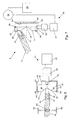
- Fig.1
- eine Explosionsdarstellung eines Lenkstockschalters mit einem integrierten, verrastbaren Blinkerschalter, dem eine erfindungsgemäße Rückstelleinrichtung zugeordnet ist,
- Fig.2
- eine vereinfachte Schnittdarstellung der Einzelheit II gemäß Fig. 1,
- Fig.3
- die Darstellung der Einzelheit II nach Fig. 2 in einer anderen Stellung des Schalthebels,
- Fig.4
- die Darstellung der Einzelheit II nach Fig. 3 in einer weiteren Stellung des Schalthebels,
- Fig.5
- eine erste alternative Ausgestaltung der Einzelheit II gemäß Fig. 1 in einer vereinfachten Schnittdarstellung,
- Fig.6
- eine zweite alternative Ausgestaltung der Einzelheit II gemäß Fig. 1 in einer vereinfachten Schnittdarstellung und
- Fig.7
- eine dritte alternative Ausgestaltung der Einzelheit II gemäß Fig. 1 in einer vereinfachten Schnittdarstellung.
- 1.
- Gehäuseoberteil
- 2.
- Gehäuseunterteil
- 3.
- Ausnehmung
- 4.
- Klipsarm
- 5.
- Klipsöffnung
- 6.
- Schalter
- 7.
- Zentrieransatz
- 8.
- Leiterplatte
- 9.
- Bohrung
- 10.
- Öffnung
- 11.
- Anschluss
- 12.
- Durchbruch
- 13.
- Durchgangsbohrung
- 14.
- Öffnung
- 15. 16.
- Leiter
- 17.
- Verbindungseinrichtung
- 18.
- Anschlusseinheit
- 19.
- Anschlusseinheit
- 20.
- Führungsausnehmung
- 21. 22.
- Deckel
- 23.
- Flansch
- 24.
- Ansatz
- 25.
- Boden
- 26.
- Freiraum
- 27. 28. 29.
- Lenkwinkelsensor
- 30.
- Rotor
- 31.
- Stator
- 32.
- Bordrechner
- 33. 34.
- Schalthebel
- 35.
- Rasthülse
- 36.
- Bund
- 37.
- Druckfeder
- 38.
- Stufenbohrung
- 39.
- Rastkurve
- 40.
- Schenkel
- 41.
- Nase
- 42.
- Verstelleinrichtung
- 43.
- Gehäusewand
- 44.
- Anschlag
- 45.
- Rückwand
- 46.
- Platte
- 47.
- Elektromagnet
- 48.
- Gehäusewand
- 49.
- Druckfeder
- 50.
- Scheitelpunkt
- 51.
- Elektromotor
- 52.
- Getriebe
- 53.
- Gewindestange
- 54.
- Seitenwand
- 55.
- Führung
- 56.
- Verrastung
- 57.
- Drehpunkt
- 58.
- Drehschenkelfeder
- 59.
- Schenkel
- 60.
- Anschlag
- 61.
- Nase
- 62.
- Anschlag
- 63.
- Rippe
- 64.
- Druckfeder
Claims (17)
- Rückstelleinrichtung für einen Schalter (6) eines Kraftfahrzeuges, insbesondere eines Blinkerschalters, mit einem schwenkbar gelagerten, verrastbaren Schalthebel (34) mit einem federbelasteten Rastelement, das mit mindestens einer Schaltstellung einer gehäuseseitigen Rastkurve (39) zusammenwirkt, dadurch gekennzeichnet, dass eine elektromechanische Verstelleinrichtung (42) rechnergesteuert die Verrastung (56) des Schalthebels (34) aufhebt.
- Rückstelleinrichtung nach Anspruch 1, dadurch gekennzeichnet, dass die Verstelleinrichtung (42) die Rastkurve (39) der Rastung beaufschlagt und im wesentlichen senkrecht oder parallel zu einer Längsachse des Schalthebels (34) wirkt.
- Rückstelleinrichtung nach Anspruch 1 oder 2, dadurch gekennzeichnet, dass die Verstelleinrichtung (42) die Rastkurve (39) kontinuierlich oder mittels eines Impulses beaufschlagt.
- Rückstelleinrichtung nach einem der Ansprüche 1 bis 3, dadurch gekennzeichnet, dass die Verstelleinrichtung (42) in ein Gehäuse des Schalters (6) integriert oder an demselben befestigt ist.
- Rückstelleinrichtung nach einem der Ansprüche 1 bis 4, dadurch gekennzeichnet, dass die Verstelleinrichtung (42) einen Elektromotor (51) umfasst, der mit einem Getriebe (52) gekoppelt ist, das wiederum über eine Gewindestange (53) mit der Rastkurve (39) in Verbindung steht.
- Rückstelleinrichtung nach Anspruch 5, dadurch gekennzeichnet, dass die Drehrichtung des Elektromotors (51) rechnergesteuert umkehrbar ist.
- Rückstelleinrichtung nach den Ansprüchen 5 und 6, dadurch gekennzeichnet, dass die Gewindestange (53) in ein Innengewinde eingreift, das in eine Rückwand (45) oder eine Seitenwand (54) der Rastkurve (39) eingelassen ist.
- Rückstelleinrichtung nach einem der Ansprüche 5 bis 7, dadurch gekennzeichnet, dass der Elektromotor (51) nach dem Lösen der Verrastung (56) des Schalthebels (34) die Rastkurve (39) rechnergesteuert in ihre Ausgangslage bewegt.
- Rückstelleinrichtung nach einem der Ansprüche 1 bis 4, dadurch gekennzeichnet, dass die Verstelleinrichtung (42) mindestens einen Elektromagneten (47) umfasst, der rechnergesteuert aktiviert auf die magnetische oder mit einer magnetischen Platte (46) versehene Rastkurve (39) wirkt und die Verrastung (56) des Schalthebels (34) löst.
- Rückstelleinrichtung nach Anspruch 9, dadurch gekennzeichnet, dass die Platte (46) in jeweils eine Seitenwand (54) oder die Rückwand (45) der Rastkurve (39) eingelassen und jeder Platte (46) ein Elektromagnet (47) zugeordnet ist.
- Rückstelleinrichtung nach den Ansprüchen 9 und 10, dadurch gekennzeichnet, dass die Rastkurve (39) in dem Gehäuse (33) geführt ist, wobei zwischen den die Platten (46) aufweisenden Seitenwänden (54) sowie den dazu korrespondierenden Gehäusewänden (43) Druckfedern (49) angeordnet sind, die die Rastkurve (39) in ihrer Ausgangslage halten.
- Rückstelleinrichtung nach einem der Ansprüche 9 bis 11, dadurch gekennzeichnet, dass der oder die Elektromagnete (47) die Rastkurve (39) entgegen der Wirkung der Druckfedern (49) bewegen.
- Rückstelleinrichtung nach einem der Ansprüche 9 bis 12, dadurch gekennzeichnet, dass die Gehäusewände (43, 48) und/oder die Seitenwände (54) bzw. die Rückwand (45) der Rastkurve (39) mit Ansätzen oder Sackbohrungen zur Fixierung der Druckfedern (49) versehen sind.
- Rückstelleinrichtung nach einem der Ansprüche 9 bis 13, dadurch gekennzeichnet, dass die Gehäusewände (43, 48) als Anschläge (44) für die Rastkurve (39) dienen.
- Rückstelleinrichtung nach einem der Ansprüche 1 bis 14, dadurch gekennzeichnet, dass der Bordrechner (32) mit einem Lenkwinkelsensor (29) gekoppelt ist und die Verstelleinrichtung (42) in Abhängigkeit von einer Drehrichtung sowie einem Drehwinkel der Lenksäule die Rastkurve (39) betätigt.
- Rückstelleinrichtung nach Anspruch 1, dadurch gekennzeichnet, dass das Rastelement mitsamt der zugeordneten Druckfeder (37) unverlierbar in dem Schalthebel (34) gehalten ist.
- Rückstelleinrichtung nach Anspruch 16, dadurch gekennzeichnet, dass das als Rasthülse (35) ausgebildete Rastelement mit einem Bund (36) versehen und in eine stirnseitige Stufenbohrung (38) des Schalthebels (34) eingesetzt ist.
Priority Applications (1)
| Application Number | Priority Date | Filing Date | Title |
|---|---|---|---|
| EP08005405A EP1939039A1 (de) | 2000-08-03 | 2001-07-25 | Rückstelleinrichtung für einen verrastbaren Schalter eines Kraftfahrzeuges |
Applications Claiming Priority (2)
| Application Number | Priority Date | Filing Date | Title |
|---|---|---|---|
| DE2000137760 DE10037760A1 (de) | 2000-08-03 | 2000-08-03 | Rückstelleinrichtung für einen Schalter eines Kraftfahrzeuges |
| DE10037760 | 2000-08-03 |
Related Child Applications (1)
| Application Number | Title | Priority Date | Filing Date |
|---|---|---|---|
| EP08005405A Division EP1939039A1 (de) | 2000-08-03 | 2001-07-25 | Rückstelleinrichtung für einen verrastbaren Schalter eines Kraftfahrzeuges |
Publications (3)
| Publication Number | Publication Date |
|---|---|
| EP1177942A2 true EP1177942A2 (de) | 2002-02-06 |
| EP1177942A3 EP1177942A3 (de) | 2006-04-26 |
| EP1177942B1 EP1177942B1 (de) | 2008-09-03 |
Family
ID=7651136
Family Applications (2)
| Application Number | Title | Priority Date | Filing Date |
|---|---|---|---|
| EP08005405A Withdrawn EP1939039A1 (de) | 2000-08-03 | 2001-07-25 | Rückstelleinrichtung für einen verrastbaren Schalter eines Kraftfahrzeuges |
| EP01117983A Expired - Lifetime EP1177942B1 (de) | 2000-08-03 | 2001-07-25 | Rückstelleinrichtung für einen Schalter eines Kraftfahrzeuges |
Family Applications Before (1)
| Application Number | Title | Priority Date | Filing Date |
|---|---|---|---|
| EP08005405A Withdrawn EP1939039A1 (de) | 2000-08-03 | 2001-07-25 | Rückstelleinrichtung für einen verrastbaren Schalter eines Kraftfahrzeuges |
Country Status (2)
| Country | Link |
|---|---|
| EP (2) | EP1939039A1 (de) |
| DE (2) | DE10037760A1 (de) |
Cited By (9)
| Publication number | Priority date | Publication date | Assignee | Title |
|---|---|---|---|---|
| EP1528366A1 (de) * | 2003-10-29 | 2005-05-04 | Wen-Wei Su | Positionsgeber mit farbkodierter Skala |
| EP1219496A3 (de) * | 2000-12-28 | 2006-05-03 | Valeo Schalter und Sensoren GmbH | Einrichtung für die Betätigung von Blinkleuchten eines Fahrzeuges |
| DE102010007424A1 (de) * | 2010-02-10 | 2011-08-11 | Valeo Schalter und Sensoren GmbH, 74321 | Hebelrückstellmechanismus |
| WO2016113282A1 (de) * | 2015-01-14 | 2016-07-21 | Leopold Kostal Gmbh & Co Kg | Lenkstockschalter für ein kraftfahrzeug |
| EP3546289A1 (de) * | 2018-03-22 | 2019-10-02 | Mazda Motor Corporation | Schaltvorrichtung für fahrzeugscheinwerfer, scheinwerfersystem, fahrzeug, verfahren zum schalten von fahrzeugscheinwerfermodi und computerprogrammprodukt |
| DE102020102995B3 (de) * | 2020-02-06 | 2021-03-04 | Audi Aktiengesellschaft | Lenkstockschalter und verfahren zum ansteuern eines elektromagneten in einem lenkstockschalter |
| WO2021216438A1 (en) * | 2020-04-20 | 2021-10-28 | Strattec Security Corporation | Cancellation device for an automotive feature |
| WO2022199802A1 (en) | 2021-03-23 | 2022-09-29 | Merit Automotive Electronics Systems S.L.U. | Rotary switch assembly with a controllable cancelling mechanism |
| WO2022248058A1 (en) | 2021-05-28 | 2022-12-01 | Merit Automotive Electronics Systems S.L.U. | Stalk switch assembly with a controllable releasing mechanism |
Families Citing this family (7)
| Publication number | Priority date | Publication date | Assignee | Title |
|---|---|---|---|---|
| DE102007036633A1 (de) | 2007-08-03 | 2009-02-05 | Man Nutzfahrzeuge Ag | Vorrichtung und Verfahren zur Betätigung von Fahrtrichtungsanzeigern bei Kraftfahrzeugen |
| DE102011110701A1 (de) | 2011-08-16 | 2013-02-21 | GM Global Technology Operations LLC (n. d. Gesetzen des Staates Delaware) | Verstelleinrichtung |
| EP3356183A4 (de) * | 2015-09-27 | 2019-05-22 | Djerroud, Idris | Beleuchtungs- und signalisierungsschalter mit halbautomatischer umschaltung von hohen strahlen zu niedrigen strahlen |
| DE102018115330A1 (de) * | 2018-06-26 | 2020-01-02 | Valeo Schalter Und Sensoren Gmbh | Rückstelleinrichtung für einen Lenkstockhebel für Kraftfahrzeuge |
| DE102018119801A1 (de) * | 2018-08-15 | 2020-02-20 | Valeo Schalter Und Sensoren Gmbh | Rückstellvorrichtung für eine Fahrrichtungsanzeigevorrichtung eines Fahrzeugs, Fahrtrichtungsanzeigevorrichtung und Fahrzeug |
| US20220072994A1 (en) * | 2018-12-04 | 2022-03-10 | Strattec Security Corporation | Cancellation device for an automotive feature |
| DE102022105240A1 (de) | 2022-03-07 | 2023-09-07 | Bayerische Motoren Werke Aktiengesellschaft | Fahrtrichtungsanzeigevorrichtung und verfahren zum anzeigen einer fahrtrichtung für ein kraftfahrzeug |
Citations (3)
| Publication number | Priority date | Publication date | Assignee | Title |
|---|---|---|---|---|
| DE2725805C2 (de) | 1977-06-08 | 1984-02-23 | Robert Bosch Gmbh, 7000 Stuttgart | Einrichtung zum Ausschalten eines Fahrtrichtungsanzeigers bei einem Kraftfahrzeug nach einer Kurvenfahrt |
| DE2721879C3 (de) | 1977-05-14 | 1985-11-14 | SWF Auto-Electric GmbH, 7120 Bietigheim-Bissingen | Schalteinrichtung zum Ansteuern der Blinklampen in Kraftfahrzeugen |
| DE19758288A1 (de) | 1997-12-31 | 1999-07-01 | Itt Mfg Enterprises Inc | Verfahren und Vorrichtung zur drehrichtungsgekoppelten Rückstellung eines Schalters |
Family Cites Families (6)
| Publication number | Priority date | Publication date | Assignee | Title |
|---|---|---|---|---|
| DE720718C (de) * | 1940-12-04 | 1942-05-13 | Herbert Becker | Schaltvorrichtung fuer Fahrtrichtungsanzeiger von Kraftfahrzeugen mit selbsttaetigerRueckschaltung des Handschalthebels |
| US4125827A (en) * | 1973-09-17 | 1978-11-14 | Roudebush Jr Robert D | Automatically cancelling turn signal |
| JPS5720424Y2 (de) * | 1975-11-14 | 1982-05-01 | ||
| JPH0447874Y2 (de) * | 1985-07-24 | 1992-11-11 | ||
| US4900946A (en) * | 1988-06-03 | 1990-02-13 | Navistar International Transportation Corp. | Multi-function switch for automotive vehicles |
| JPH0422335U (de) * | 1990-06-19 | 1992-02-25 |
-
2000
- 2000-08-03 DE DE2000137760 patent/DE10037760A1/de not_active Withdrawn
-
2001
- 2001-07-25 EP EP08005405A patent/EP1939039A1/de not_active Withdrawn
- 2001-07-25 EP EP01117983A patent/EP1177942B1/de not_active Expired - Lifetime
- 2001-07-25 DE DE50114277T patent/DE50114277D1/de not_active Expired - Fee Related
Patent Citations (3)
| Publication number | Priority date | Publication date | Assignee | Title |
|---|---|---|---|---|
| DE2721879C3 (de) | 1977-05-14 | 1985-11-14 | SWF Auto-Electric GmbH, 7120 Bietigheim-Bissingen | Schalteinrichtung zum Ansteuern der Blinklampen in Kraftfahrzeugen |
| DE2725805C2 (de) | 1977-06-08 | 1984-02-23 | Robert Bosch Gmbh, 7000 Stuttgart | Einrichtung zum Ausschalten eines Fahrtrichtungsanzeigers bei einem Kraftfahrzeug nach einer Kurvenfahrt |
| DE19758288A1 (de) | 1997-12-31 | 1999-07-01 | Itt Mfg Enterprises Inc | Verfahren und Vorrichtung zur drehrichtungsgekoppelten Rückstellung eines Schalters |
Cited By (11)
| Publication number | Priority date | Publication date | Assignee | Title |
|---|---|---|---|---|
| EP1219496A3 (de) * | 2000-12-28 | 2006-05-03 | Valeo Schalter und Sensoren GmbH | Einrichtung für die Betätigung von Blinkleuchten eines Fahrzeuges |
| EP1528366A1 (de) * | 2003-10-29 | 2005-05-04 | Wen-Wei Su | Positionsgeber mit farbkodierter Skala |
| DE102010007424A1 (de) * | 2010-02-10 | 2011-08-11 | Valeo Schalter und Sensoren GmbH, 74321 | Hebelrückstellmechanismus |
| DE102010007424B4 (de) * | 2010-02-10 | 2019-09-12 | Valeo Schalter Und Sensoren Gmbh | Hebelrückstellmechanismus |
| WO2016113282A1 (de) * | 2015-01-14 | 2016-07-21 | Leopold Kostal Gmbh & Co Kg | Lenkstockschalter für ein kraftfahrzeug |
| US10207732B2 (en) | 2015-01-14 | 2019-02-19 | Leopold Kostal Gmbh & Co. Kg | Steering column switch for a motor vehicle |
| EP3546289A1 (de) * | 2018-03-22 | 2019-10-02 | Mazda Motor Corporation | Schaltvorrichtung für fahrzeugscheinwerfer, scheinwerfersystem, fahrzeug, verfahren zum schalten von fahrzeugscheinwerfermodi und computerprogrammprodukt |
| DE102020102995B3 (de) * | 2020-02-06 | 2021-03-04 | Audi Aktiengesellschaft | Lenkstockschalter und verfahren zum ansteuern eines elektromagneten in einem lenkstockschalter |
| WO2021216438A1 (en) * | 2020-04-20 | 2021-10-28 | Strattec Security Corporation | Cancellation device for an automotive feature |
| WO2022199802A1 (en) | 2021-03-23 | 2022-09-29 | Merit Automotive Electronics Systems S.L.U. | Rotary switch assembly with a controllable cancelling mechanism |
| WO2022248058A1 (en) | 2021-05-28 | 2022-12-01 | Merit Automotive Electronics Systems S.L.U. | Stalk switch assembly with a controllable releasing mechanism |
Also Published As
| Publication number | Publication date |
|---|---|
| EP1177942B1 (de) | 2008-09-03 |
| EP1177942A3 (de) | 2006-04-26 |
| DE10037760A1 (de) | 2002-02-14 |
| DE50114277D1 (de) | 2008-10-16 |
| EP1939039A1 (de) | 2008-07-02 |
Similar Documents
| Publication | Publication Date | Title |
|---|---|---|
| DE4343339C2 (de) | Kraftfahrzeugtürverschluß mit Kindersicherungseinrichtung | |
| DE19635414C2 (de) | Schloß, insbesondere für Fahrzeugtüren oder dergleichen | |
| EP1177942A2 (de) | Rückstelleinrichtung für einen Schalter eines Kraftfahrzeuges | |
| DE10065569B4 (de) | Vorrichtung zum Öffnen und Schließen von Kraftfahrzeugschlössern | |
| EP1848903B1 (de) | Elektrische schalteinrichtung für ein kraftfahrzeug | |
| EP1225290B1 (de) | Kraftfahrzeugtürverschluss | |
| EP3469175B1 (de) | Türgriffmodul für ein kraftfahrzeug | |
| EP2539188B1 (de) | Lenkschlossvorrichtung für ein kraftfahrzeug | |
| DE102006029774A1 (de) | Griffvorrichtung | |
| EP1279576B1 (de) | Zündschlosssystem für ein Kraftfahrzeug | |
| DE3905698C1 (en) | Device for locking the gear shift lever of a motor vehicle | |
| DE4446613A1 (de) | Lenkradverriegelung an einem Kraftfahrzeug | |
| DE19957046A1 (de) | Schließsystem, insbesondere für Kraftfahrzeuge | |
| EP1143093B1 (de) | Kraftfahrzeug-Türschloss mit elastisch auslenkbarem Kupplungselement | |
| DE4005641C2 (de) | ||
| DE19547724A1 (de) | Schloß, insbesondere für Kraftfahrzeugtüren | |
| EP0432469A2 (de) | Kraftfahrzeug-Türschloss | |
| DE102017108752A1 (de) | Schloss mit Zuzieheinrichtung für ein Kraftfahrzeug | |
| EP2034112A1 (de) | Kraftfahrzeug-Türschloß | |
| EP1418298B1 (de) | Schliesshilfe zum Verschliessen einer Fahrzeugtür | |
| EP3227147B1 (de) | Verriegelungseinrichtung für ein kraftfahrzeug | |
| EP3819449A1 (de) | Kraftfahrzeugschloss | |
| DE10002776A1 (de) | Elektromotorischer Stellantrieb für ein Kraftfahrzeugschloß | |
| DE10107992A1 (de) | Zündschloßsystem für ein Kraftfahrzeug | |
| DE4221671C2 (de) | Stellelement für die Entriegelung einer Schließeinrichtung |
Legal Events
| Date | Code | Title | Description |
|---|---|---|---|
| PUAI | Public reference made under article 153(3) epc to a published international application that has entered the european phase |
Free format text: ORIGINAL CODE: 0009012 |
|
| AK | Designated contracting states |
Kind code of ref document: A2 Designated state(s): AT BE CH CY DE DK ES FI FR GB GR IE IT LI LU MC NL PT SE TR |
|
| AX | Request for extension of the european patent |
Free format text: AL;LT;LV;MK;RO;SI |
|
| PUAL | Search report despatched |
Free format text: ORIGINAL CODE: 0009013 |
|
| AK | Designated contracting states |
Kind code of ref document: A3 Designated state(s): AT BE CH CY DE DK ES FI FR GB GR IE IT LI LU MC NL PT SE TR |
|
| AX | Request for extension of the european patent |
Extension state: AL LT LV MK RO SI |
|
| 17P | Request for examination filed |
Effective date: 20061006 |
|
| 17Q | First examination report despatched |
Effective date: 20061102 |
|
| AKX | Designation fees paid |
Designated state(s): DE FR GB |
|
| 17Q | First examination report despatched |
Effective date: 20061102 |
|
| GRAP | Despatch of communication of intention to grant a patent |
Free format text: ORIGINAL CODE: EPIDOSNIGR1 |
|
| GRAS | Grant fee paid |
Free format text: ORIGINAL CODE: EPIDOSNIGR3 |
|
| GRAA | (expected) grant |
Free format text: ORIGINAL CODE: 0009210 |
|
| AK | Designated contracting states |
Kind code of ref document: B1 Designated state(s): DE FR GB |
|
| REG | Reference to a national code |
Ref country code: GB Ref legal event code: FG4D Free format text: NOT ENGLISH |
|
| REF | Corresponds to: |
Ref document number: 50114277 Country of ref document: DE Date of ref document: 20081016 Kind code of ref document: P |
|
| PLBE | No opposition filed within time limit |
Free format text: ORIGINAL CODE: 0009261 |
|
| STAA | Information on the status of an ep patent application or granted ep patent |
Free format text: STATUS: NO OPPOSITION FILED WITHIN TIME LIMIT |
|
| 26N | No opposition filed |
Effective date: 20090604 |
|
| GBPC | Gb: european patent ceased through non-payment of renewal fee |
Effective date: 20090725 |
|
| REG | Reference to a national code |
Ref country code: FR Ref legal event code: ST Effective date: 20100331 |
|
| PG25 | Lapsed in a contracting state [announced via postgrant information from national office to epo] |
Ref country code: FR Free format text: LAPSE BECAUSE OF NON-PAYMENT OF DUE FEES Effective date: 20090731 |
|
| PG25 | Lapsed in a contracting state [announced via postgrant information from national office to epo] |
Ref country code: GB Free format text: LAPSE BECAUSE OF NON-PAYMENT OF DUE FEES Effective date: 20090725 |
|
| PG25 | Lapsed in a contracting state [announced via postgrant information from national office to epo] |
Ref country code: DE Free format text: LAPSE BECAUSE OF NON-PAYMENT OF DUE FEES Effective date: 20100202 |