EP1177942A2 - Switch reset device for vehicle - Google Patents
Switch reset device for vehicle Download PDFInfo
- Publication number
- EP1177942A2 EP1177942A2 EP01117983A EP01117983A EP1177942A2 EP 1177942 A2 EP1177942 A2 EP 1177942A2 EP 01117983 A EP01117983 A EP 01117983A EP 01117983 A EP01117983 A EP 01117983A EP 1177942 A2 EP1177942 A2 EP 1177942A2
- Authority
- EP
- European Patent Office
- Prior art keywords
- curve
- reset device
- latching
- shift lever
- locking
- Prior art date
- Legal status (The legal status is an assumption and is not a legal conclusion. Google has not performed a legal analysis and makes no representation as to the accuracy of the status listed.)
- Granted
Links
Images


Classifications
-
- B—PERFORMING OPERATIONS; TRANSPORTING
- B60—VEHICLES IN GENERAL
- B60Q—ARRANGEMENT OF SIGNALLING OR LIGHTING DEVICES, THE MOUNTING OR SUPPORTING THEREOF OR CIRCUITS THEREFOR, FOR VEHICLES IN GENERAL
- B60Q1/00—Arrangement of optical signalling or lighting devices, the mounting or supporting thereof or circuits therefor
- B60Q1/26—Arrangement of optical signalling or lighting devices, the mounting or supporting thereof or circuits therefor the devices being primarily intended to indicate the vehicle, or parts thereof, or to give signals, to other traffic
- B60Q1/34—Arrangement of optical signalling or lighting devices, the mounting or supporting thereof or circuits therefor the devices being primarily intended to indicate the vehicle, or parts thereof, or to give signals, to other traffic for indicating change of drive direction
- B60Q1/40—Arrangement of optical signalling or lighting devices, the mounting or supporting thereof or circuits therefor the devices being primarily intended to indicate the vehicle, or parts thereof, or to give signals, to other traffic for indicating change of drive direction having mechanical, electric or electronic automatic return to inoperative position
Definitions
- the invention relates to a reset device for a switch of a motor vehicle, in particular one Turn signal switch, with a swivel-mounted, latchable Shift lever with a spring-loaded locking element, the with at least one switch position on the housing side Rest curve interacts.
- From DE-C-27 21 879 is a steering column switch with a buttoned turn signal switch known, the shift lever for the lane change flashing or for the direction indicator one to the right and one to the left one after the other two assigned pushbuttons.
- the on state the turn signal switch is operated by means of an electronic Holding device stored and by an electronic Reset device, the holding device is reset.
- the shift lever is actuated by a spring Switch bridge automatically in a neutral position reset.
- DE 197 58 288 A1 also discloses a device for resetting one with a direction of rotation Steering column interacting turn signal switch in a motor vehicle with a turn signal lever that can be swiveled around an axis of rotation, the turn signal lever in each of two, in the desired flashing position corresponding operating position is pivotable.
- a stationary backdrop is provided to guide the left turn signal lever end .
- the turn signal switch comprises two detents arranged on a detent element, that protrude beyond the backdrop contour and each hold the turn signal lever end in an operating position.
- the Locking element is movable, so that at least one detent each is flush with the backdrop contour and the in the Indicator position held released releases, with a steering column-fixed actuating element acts on the locking element and panned this.
- the turn signal switch must be in immediate Be arranged near the steering column and between the actuating element and the latching element may not additional components are located to the function of the device sure.
- DE 27 25 805 C2 is a device for switching off a direction indicator of a motor vehicle known after cornering, with stationary, magnetic field-controlled by means of a magnet attached to the steering column Donors are provided.
- These donors are Downstream electronic rotation discriminator, the depending on the signal sequence of the encoders when turning back turning off the steering wheel after cornering Direction display causes. This facility is only in connection with a buttoned turn signal switch use, since it does not interact with a catch, but only turns off the direction indicator.
- Wiper / washer switches for motor vehicles are also known, whose shift lever for the front wiper functions in and can be pivoted counterclockwise in a housing are stored and for the front / washer and rear / wiper / Washer functions are the shift levers in and against the direction of a dashboard pivoted.
- the Switch functions can be mechanically locked as well can also be executed by key.
- a computer controlled electromechanical adjustment device Latches the shift lever.
- the release of the switch is thus canceled not by means of a reset on the motor vehicle side by means of the electromechanical adjustment device that the Switch is assigned directly. Instead of complex mechanics to act on the detent between the same and the motor vehicle acts, the coupling with the Motor vehicle via the on-board computer. If the repeal of the Locking depending on the angle of rotation of a steering column should take place, as is the case, for example, with a turn signal switch is required, the switch does not have to be in immediate Arranged near the steering column and mechanically with it be coupled. Rather, the angle of rotation of the steering column captured by the on-board computer, which also sets or Not setting the switch detects. If a predetermined one Angle of rotation is reached, the on-board computer speaks the adjusting device to unlock the switch on. The on-board computer can of course also do this with Existence of other relevant data, such as at Expiration of a given period of time or certain reactions of the driver.
- the adjusting device preferably acts on the locking curve the detent and acts essentially perpendicular or parallel to a longitudinal axis of the shift lever.
- the adjustment device therefore only causes rectilinear movements of the locking curve, which are easier to implement than swivel movements, to operate the shift lever when it is reset would be required.
- the adjusting device expediently acts on the Resting curve continuously or by means of an impulse. If to cancel the locking the locking curve only one relative a short impulse is sufficient the adjustment device on the locking curve to the locking element of the shift lever to move back, whereupon the locking curve in their restless position returns. When putting it back relatively large distances or a relatively large power transmission is necessary, the adjustment device acts on the Resting curve continuously.
- the adjustment device is advantageously available integrated in a housing of the switch or attached to the same.
- the adjustment device an electric motor with a gear is coupled, which in turn via a threaded rod is connected to the rest curve.
- connection between the electric motor and the locking curve expediently engages the threaded rod in an internal thread one that is in a rear wall or a side wall of the locking curve is let in.
- the electric motor preferably moves after the latching has been released the shift lever the locking curve computer controlled in your Starting position.
- the locking curve is in their home position and the shift lever is in one of its Switch positions locked and the locking should be released then the on-board computer controls the electric motor in a certain direction of rotation, in which the locking curve to release the locking of the shift lever from it Starting position moved.
- the on-board computer registers that the shift lever is not in any of its shift positions located and controls the electric motor in the opposite Direction of rotation to bring the locking curve into its starting position reset.
- the adjusting device has at least one electromagnet, the computer controlled activated on the magnetic or latching curve provided with a magnetic plate acts and releases the shift lever.
- the interaction of the Electromagnets with the magnetic or with the magnetic Plate provided locking curve is sufficient when activated, around the locking curve an impulse to leave its starting position impress and thus the locking between the locking curve and the gear lever in its locked Cancel switch position.
- plastic is usually used to metallize it not be sufficient to achieve the required magnetic effect to achieve, which is why the metallic plate in appropriate Size as insert or to be assembled later Part of the rest curve is assigned.
- the plate is preferably in one side wall or the The rear wall of the locking curve is inserted and each plate has an electromagnet assigned.
- the locking curve can be passed through pulling one electromagnet into position, in which the gear lever locks into a gear position can, and by tightening the other electromagnet the rest curve is conveyed out of this position and the Disengaged.
- the locking curve is one Housing guided, being between those having the plates Side walls and the corresponding housing walls Compression springs are arranged in the locking curve keep their starting position. From the starting position of the rest curve the shift lever can be locked in one or the other Switch position can be pivoted. The guides for the Latch curve prevent uncontrolled movement of the same.
- the electromagnet advantageously move the Latch curve against the action of the compression springs.
- the switch position in which the Shift lever is located and speaks the corresponding electromagnet on the locking curve to cancel the locking acted against the spring force. After resetting of the electromagnet reverses the locking curve due to the spring action back to their starting position.
- the on-board computer is preferably coupled to a steering angle sensor and the adjusting device operates in dependence of a direction of rotation and an angle of rotation of the steering column the rest curve.
- the steering angle sensor coupled to the steering column permanently records changes in direction of rotation and angle of rotation the steering column and provides this data for evaluation to the on-board computer, which then, if necessary, the adjustment device applied.
- the locking is released a turn signal switch when the direction of rotation changes Steering column ensured without the switch in a direct mechanical contact to the steering column.
- the measured values of the steering angle sensor can be taken for granted Assign tolerance ranges so that the adjustment device not with every little change in the direction of rotation is addressed by the on-board computer.
- Locking sleeve designed locking element provided with a collar and inserted into an end step bore of the shift lever.
- the steering column switch comprises a housing upper part 1 and a lower housing part 2 composite housing, wherein on the lower housing part 2 a cylindrical recess 3 for Attachment of the steering column switch to a not shown Jacket tube of a motor vehicle is formed.
- the lower housing part comprises 2 clip arms 4 on the edge, that when joining the lower housing part 2 and the upper housing part 1 in corresponding clip openings 5 of the upper housing part 1 engage, as well as centering openings, not shown, in the corresponding centering lugs 7 of the Upper housing part 1 are used.
- the lower part of the housing 2 assigned a circuit board 8, with a Vehicle electrical system and an on-board computer 32 of the motor vehicle is coupled.
- the circuit board 8 has one with the recess 3 of the lower housing part 2 and with a bore 9 of the upper housing part 1 aligned cylindrical opening 10 for performing a Steering column, not shown, whose free end above of the upper housing part 1 is connected to a steering wheel.
- Farther is the circuit board 8 with connections 11 for substantially opposite switch 6 provided, of which only one is shown.
- the trained as a turn signal switch latchable switch 6 has a shift lever 34 on, which penetrates an opening 12 of the upper housing part 1 and the through holes 13 on the circuit board side penetrating screw connections on the lower housing part 2 is set.
- the circuit board 8 with an ignition lock connected in a between the upper housing part 1 and the housing lower part 2 formed opening 14 is used becomes.
- the upper housing part overlapping the edge of the housing 2 1 has a recess for receiving an electrical Conductor 16 of an electrical connection device 17 on the steering wheel on the circuit board 8 with the electrical system coupled.
- the flexible conductor 16 is in several Windings wound spirally and with each end a connection unit 18, 19, the one connection unit 18 in a guide recess 20 of the upper housing part 1 used and coupled to the circuit board 8 is.
- the other connection unit 19, which with the steering wheel in Is connected, is inserted into an opening of a cover 22, a flange 23 for fastening on the steering wheel side comprises, on which an extension 24 is coaxially formed.
- the Flange 23 of the cover 22 covers the conductor 16, which is on a bottom 25 formed by the upper housing part 1 supported.
- the neck 24 is rotatably inserted in the bottom 25, the projection 24 one formed by the conductor 16 Open space 26 extends through.
- the lateral limitation of the conductor 16 is from one of a housing top to the bottom 25 extending wall of the upper housing part 1 is formed.
- a steering angle sensor 29 is arranged which is essentially consists of a rotor 30 and a stator 31, the stator 31 via the printed circuit board 8 with the on-board computer 32 is coupled.
- the switch 6 comprises a pivotally mounted on the housing side Shift lever 34 with a designed as a locking sleeve 35 Locking element.
- a collar 36 is formed on the locking sleeve 35, the together with a compression spring 37 in a stepped bore 38 of the shift lever 34 is captively inserted.
- the locking sleeve 35 acts with a housing side Rest curve 39 together.
- the locking curve 39 is in designed essentially V-shaped, with at the ends of the Leg 40 of the V-shape small noses 41 are formed and each of the lugs 41 the shift lever 34 in one of its locked Switch positions holds.
- the locking curve 39 is an adjusting device 42 assigned to the latch 56 of the To lift the shift lever 34. So that the shift lever 34 always returns to its unlocked position is on a pivot leg spring 58 is arranged at its fulcrum 57, the Leg 59 a stop 60 fixed to the housing and a grasp nose 61 associated with shift lever 34.
- the torsion spring 58 When swiveling of the shift lever 34 in a locked switching position, the torsion spring 58 is tensioned and pivoted the shift lever 34 in its release of the latch 56 Starting position. Furthermore, the switching lever 34 are fixed stops 62 associated with its pivoting over a predetermined Prevent end position beyond.
- the locking curve 39 is guided between the housing walls 43 the free ends of stops 44 are formed.
- the rear wall 45 of the locking curve 39 is a metallic plate 46 used with an electromagnet 47 of the adjusting device 42 cooperates.
- compression springs are supported 49, which press the locking curve 39 against the stops 44.
- the shift lever 34 be pivoted into a locked position in which the Locking sleeve 35 engages behind the associated nose 41 of the locking curve 39.
- the opposite Side walls 54 of the locking curve 39 each have a metallic one Plate 46 assigned and on the side housing walls 43rd is in each case an electromagnet corresponding to a plate 46 47 attached, between the electromagnet 47 and the associated side wall 54 of preloaded compression springs 49 are arranged.
- the locking curve 39 is by means of a guide 55 substantially perpendicular to the longitudinal axis of the shift lever 34 movable between the side housing walls 43 stored.
- the shift lever 34 is in one of the locked Switch positions of the switch 6, in which the locking sleeve 35 engages behind the associated nose 41 of the locking curve 39 and should the latching 56 be released, so the on-board computer 32 speaks to the electromagnet 47 which on the side of the switch assigned to the latch 56 6 is located.
- the electromagnet 47 then pulls the Plate 46 and thus also the locking curve 39 against the effect of the associated compression springs 49 and the locking sleeve 35 slides over the nose 41 and then on the corresponding leg 40 of the locking curve 39 in a not locked position in which it is at the apex 50 in the Latch curve 39 lies.
- the on-board computer 32 interrupts the power supply to the electromagnet 47 and the locking curve 39 returns under the effect of Compression springs 49 return to their starting position in which they are between the correspondingly designed compression springs 37 held becomes.
- the Adjustment device 42 an electric motor 51, on the one hand with a gear 52 and on the other hand with the on-board computer 32 is coupled.
- the gear 52 stands over a threaded rod 53 with the locking curve 39 in connection, being in the rear wall 45 of the locking curve 39, a thread for the threaded rod 53 is inserted is.
- the electric motor 51 is computer controlled into an inverted one Direction of rotation offset, whereupon he the locking curve 39 in again Direction of the shift lever 34 transported, which then by corresponding pivoting a locked switch position can take.
- the threaded rod 53 of the adjusting device 42 can also in a side wall 54 of the locking curve 39 are used, wherein both the gear 52 and the electric motor 51 of the corresponding lateral housing wall 43 are assigned.
- the electric motor 51 addressed by the on-board computer 32 moves in this arrangement, the locking curve 39 in the guide 55 substantially perpendicular to the longitudinal axis of the shift lever 34.
Abstract
Description
Die Erfindung bezieht sich auf eine Rückstelleinrichtung für einen Schalter eines Kraftfahrzeuges, insbesondere eines Blinkerschalters, mit einem schwenkbar gelagerten, verrastbaren Schalthebel mit einem federbelasteten Rastelement, das mit mindestens einer Schaltstellung einer gehäuseseitigen Rastkurve zusammenwirkt.The invention relates to a reset device for a switch of a motor vehicle, in particular one Turn signal switch, with a swivel-mounted, latchable Shift lever with a spring-loaded locking element, the with at least one switch position on the housing side Rest curve interacts.
Aus der DE-C-27 21 879 ist ein Lenkstockschalter mit einem getasteten Blinkerschalter bekannt, dessen Schalthebel für das Fahrbahnwechselblinken oder für die Fahrtrichtungsanzeige nach rechts und nach links jeweils nacheinander einen oder zwei zugeordnete Tastschalter beaufschlagt. Der Einschaltzustand des Blinkerschalters wird mittels einer elektronischen Halteeinrichtung gespeichert und durch eine elektronische Rücksetzeinrichtung wird die Halteeinrichtung zurückgesetzt. Der Schalthebel wird nach seiner Betätigung durch eine federbeaufschlagte Schaltbrücke selbsttätig in eine Neutralstellung zurückgestellt.From DE-C-27 21 879 is a steering column switch with a buttoned turn signal switch known, the shift lever for the lane change flashing or for the direction indicator one to the right and one to the left one after the other two assigned pushbuttons. The on state the turn signal switch is operated by means of an electronic Holding device stored and by an electronic Reset device, the holding device is reset. The shift lever is actuated by a spring Switch bridge automatically in a neutral position reset.
Im Weiteren offenbart die DE 197 58 288 A1 eine Vorrichtung zur drehrichtungsgekoppelten Rückstellung eines mit einer Lenksäule zusammenwirkenden Blinkerschalters in einem Kraftfahrzeug mit einem um eine Drehachse schwenkbaren Blinkerhebel, wobei der Blinkerhebel jeweils in eine von zwei, in der gewünschten Blinkstellung entsprechende Betriebstellung schwenkbar ist. Zur Führung des linken Blinkerhebelendes ist eine ortsfest angeordnete Kulisse vorgesehen. Der Blinkerschalter umfasst zwei auf einem Rastelement angeordnete Rastungen, die über die Kulissenkontur hervorstehen und jeweils das Blinkerhebelende in einer Betriebstellung halten. Das Rastelement ist bewegbar, so dass jeweils eine Rastung zumindest bündig mit der Kulissenkontur abschließt und den in der Betriebstellung gehaltenen Blinkerhebel freigibt, wobei ein lenksäulenfestes Betätigungselement auf das Rastelement einwirkt und dieses verschwenkt. Der Blinkerschalter muss in unmittelbarer Nähe der Lenksäule angeordnet sein und zwischen dem Betätigungselement und dem Rastelement dürfen sich keine weiteren Bauteile befinden, um die Funktion der Vorrichtung sicherzustellen.DE 197 58 288 A1 also discloses a device for resetting one with a direction of rotation Steering column interacting turn signal switch in a motor vehicle with a turn signal lever that can be swiveled around an axis of rotation, the turn signal lever in each of two, in the desired flashing position corresponding operating position is pivotable. To guide the left turn signal lever end a stationary backdrop is provided. The turn signal switch comprises two detents arranged on a detent element, that protrude beyond the backdrop contour and each hold the turn signal lever end in an operating position. The Locking element is movable, so that at least one detent each is flush with the backdrop contour and the in the Indicator position held released releases, with a steering column-fixed actuating element acts on the locking element and panned this. The turn signal switch must be in immediate Be arranged near the steering column and between the actuating element and the latching element may not additional components are located to the function of the device sure.
Darüberhinaus ist aus der DE 27 25 805 C2 eine Einrichtung zum Ausschalten eines Fahrtrichtungsanzeigers eines Kraftfahrzeuges nach einer Kurvenfahrt bekannt, wobei ortsfeste, mittels eines an der Lenksäule angebrachten Magneten magnetfeldgesteuerte Geber vorgesehen sind. Diesen Gebern ist ein elektronischer Drehrichtungsdiskriminator nachgeschaltet, der in Abhängigkeit von der Signalfolge der Geber beim Rückdrehen des Lenkrades nach einer Kurvenfahrt die Ausschaltung der Fahrtrichtungsanzeige bewirkt. Diese Einrichtung ist lediglich in Verbindung mit einem getasteten Blinkerschalter zu verwenden, da sie nicht mit einer Rastung zusammenwirkt, sondern lediglich die Fahrtrichtungsanzeige ausschaltet.In addition, DE 27 25 805 C2 is a device for switching off a direction indicator of a motor vehicle known after cornering, with stationary, magnetic field-controlled by means of a magnet attached to the steering column Donors are provided. These donors are Downstream electronic rotation discriminator, the depending on the signal sequence of the encoders when turning back turning off the steering wheel after cornering Direction display causes. This facility is only in connection with a buttoned turn signal switch use, since it does not interact with a catch, but only turns off the direction indicator.
Ferner sind Wischer-/Wascherschalter für Kraftfahrzeuge bekannt, deren Schalthebel für die Front-Wischerfunktionen im und gegen den Uhrzeigersinn verschwenkbar in einem Gehäuse gelagert sind und für die Front/Wascher- und Heck-/Wischer-/ Wascherfunktionen sind die Schalthebel in und gegen die Richtung eines Armaturenbrettes verschwenkbar gelagert. Die Schalterfunktionen können sowohl mechanisch verrastend als auch getastet ausgeführt werden.Wiper / washer switches for motor vehicles are also known, whose shift lever for the front wiper functions in and can be pivoted counterclockwise in a housing are stored and for the front / washer and rear / wiper / Washer functions are the shift levers in and against the direction of a dashboard pivoted. The Switch functions can be mechanically locked as well can also be executed by key.
Es ist Aufgabe der Erfindung, eine Rückstelleinrichtung für einen Schalter eines Kraftfahrzeuges der eingangs genannten Art zu schaffen, die eine Aufhebung der Verrastung mit einem geringen mechanischen Aufwand ermöglicht.It is an object of the invention to provide a reset device for a switch of a motor vehicle of the type mentioned Kind of creating a release from the lock with one allows little mechanical effort.
Erfindungsgemäß wird die Aufgabe dadurch gelöst, dass eine elektromechanische Verstelleinrichtung rechnergesteuert die Verrastung des Schalthebels aufhebt.According to the invention the object is achieved in that a computer controlled electromechanical adjustment device Latches the shift lever.
Die Aufhebung der Verrastung des Schalters erfolgt somit nicht mittels einer kraftfahrzeugseitigen Rücksetzung sondern mittels der elektromechanischen Verstelleinrichtung, die dem Schalter direkt zugeordnet ist. Anstatt einer aufwendigen Mechanik zur Beaufschlagung der Rastung, die zwischen derselben und dem Kraftfahrzeug wirkt, erfolgt die Kopplung mit dem Kraftfahrzeug über den Bordrechner. Falls die Aufhebung der Verrastung in Abhängigkeit von dem Drehwinkel einer Lenksäule erfolgen soll, wie es beispielsweise bei einem Blinkerschalter erforderlich ist, muss der Schalter nicht in unmittelbarer Nähe der Lenksäule angeordnet und mechanisch mit dieser gekoppelt werden. Vielmehr wird der Drehwinkel der Lenksäule von dem Bordrechner erfasst, der gleichfalls das Setzen bzw. Nichtsetzen des Schalters erkennt. Falls ein vorbestimmter Drehwinkel erreicht ist, spricht der Bordrechner die Verstelleinrichtung zur Aufhebung der Verrastung des Schalters an. Der Bordrechner kann dies selbstverständlich auch beim Vorliegen anderer relevanter Daten, wie beispielsweise bei Ablauf einer vorgegebenen Zeitspanne oder bestimmter Reaktionen des Fahrers, veranlassen.The release of the switch is thus canceled not by means of a reset on the motor vehicle side by means of the electromechanical adjustment device that the Switch is assigned directly. Instead of complex mechanics to act on the detent between the same and the motor vehicle acts, the coupling with the Motor vehicle via the on-board computer. If the repeal of the Locking depending on the angle of rotation of a steering column should take place, as is the case, for example, with a turn signal switch is required, the switch does not have to be in immediate Arranged near the steering column and mechanically with it be coupled. Rather, the angle of rotation of the steering column captured by the on-board computer, which also sets or Not setting the switch detects. If a predetermined one Angle of rotation is reached, the on-board computer speaks the adjusting device to unlock the switch on. The on-board computer can of course also do this with Existence of other relevant data, such as at Expiration of a given period of time or certain reactions of the driver.
Bevorzugt beaufschlagt die Verstelleinrichtung die Rastkurve der Rastung und wirkt im wesentlichen senkrecht oder parallel zu einer Längsachse des Schalthebels. Die Verstelleinrichtung verursacht also lediglich geradlinige Bewegungen der Rastkurve, die einfacher zu realisieren sind als Schwenkbewegungen, die zur Betätigung des Schalthebels bei dessen Rücksetzung erforderlich wären.The adjusting device preferably acts on the locking curve the detent and acts essentially perpendicular or parallel to a longitudinal axis of the shift lever. The adjustment device therefore only causes rectilinear movements of the locking curve, which are easier to implement than swivel movements, to operate the shift lever when it is reset would be required.
Zweckmäßigerweise beaufschlagt die Verstelleinrichtung die Rastkurve kontinuierlich oder mittels eines Impulses. Falls zur Aufhebung der Verrastung die Rastkurve nur einen relativ geringen Weg zurücklegen muss, genügt ein stoßartiger Impuls der Verstelleinrichtung auf die Rastkurve, um das Rastelement des Schalthebels zurück zu bewegen, worauf die Rastkurve in ihre unverrastste Stellung zurückkehrt. Wenn das Zurücklegen relativ großer Wege oder eine relativ große Kraftübertragung erforderlich ist, beaufschlagt die Verstelleinrichtung die Rastkurve kontinuierlich.The adjusting device expediently acts on the Resting curve continuously or by means of an impulse. If to cancel the locking the locking curve only one relative a short impulse is sufficient the adjustment device on the locking curve to the locking element of the shift lever to move back, whereupon the locking curve in their restless position returns. When putting it back relatively large distances or a relatively large power transmission is necessary, the adjustment device acts on the Resting curve continuously.
Um eine kompakte Bauform und eine leicht handhabbare Einheit zur Verfügung zu stellen, ist vorteilhafterweise die Verstelleinrichtung in ein Gehäuse des Schalters integriert oder an demselben befestigt.A compact design and an easy-to-use unit The adjustment device is advantageously available integrated in a housing of the switch or attached to the same.
Nach einer vorteilhaften Ausgestaltung der Erfindung umfasst die Verstelleinrichtung einen Elektromotor, der mit einem Getriebe gekoppelt ist, das wiederum über eine Gewindestange mit der Rastkurve in Verbindung steht. Mit dem Getriebe lässt sich eine zur Beaufschlagung der Rastkurve erforderliche Übersetzung erzielen und darüber hinaus stellt der Elektromotor neben einer kontinuierlichen Beaufschlagung der Rastkurve auch die Übertragung relativ großer Kräfte sicher.According to an advantageous embodiment of the invention the adjustment device an electric motor with a gear is coupled, which in turn via a threaded rod is connected to the rest curve. With the gearbox a necessary for loading the locking curve Achieve translation and beyond that the electric motor provides in addition to a continuous loading of the rest curve the transmission of relatively large forces is also safe.
Um die Rastkurve aus einer bestimmten Stellung herauszubewegen und anschließend wieder in diese Stellung zurückzubringen, ist zweckmäßigerweise die Drehrichtung des Elektromotors rechnergesteuert umkehrbar. Hierbei speichert der Bordrechner die jeweils letzte Drehrichtung des Elektromotors.To move the locking curve out of a certain position and then return to that position is expedient the direction of rotation of the electric motor computer controlled reversible. The on-board computer saves here the last direction of rotation of the electric motor.
Zur Realisierung einer zuverlässigen sowie einfach zu fertigenden Verbindung zwischen dem Elektromotor und der Rastkurve greift zweckmäßigerweise die Gewindestange in ein Innengewinde ein, das in eine Rückwand oder eine Seitenwand der Rastkurve eingelassen ist.To realize a reliable as well as easy to manufacture Connection between the electric motor and the locking curve expediently engages the threaded rod in an internal thread one that is in a rear wall or a side wall of the locking curve is let in.
Bevorzugt bewegt der Elektromotor nach dem Lösen der Verrastung des Schalthebels die Rastkurve rechnergesteuert in ihre Ausgangslage. Befindet sich beispielsweise die Rastkurve in ihrer Ausgangsstellung und der Schalthebel ist in einer seiner Schaltstellungen verrastet und die Verrastung soll aufgehoben werden, dann steuert der Bordrechner den Elektromotor in einer bestimmten Drehrichtung an, in der sich die Rastkurve zur Aufhebung der Verrastung des Schalthebels aus ihrer Ausgangslage bewegt. Der Bordrechner registriert anschließend, dass sich der Schalthebel in keiner seiner Schaltstellungen befindet und steuert den Elektromotor in entgegengesetzter Drehrichtung an, um die Rastkurve in ihre Ausgangslage zurückzustellen.The electric motor preferably moves after the latching has been released the shift lever the locking curve computer controlled in your Starting position. For example, the locking curve is in their home position and the shift lever is in one of its Switch positions locked and the locking should be released then the on-board computer controls the electric motor in a certain direction of rotation, in which the locking curve to release the locking of the shift lever from it Starting position moved. The on-board computer then registers that the shift lever is not in any of its shift positions located and controls the electric motor in the opposite Direction of rotation to bring the locking curve into its starting position reset.
Bei einer alternativen Ausführung des Erfindungsgedankens umfasst die Verstelleinrichtung mindestens einen Elektromagneten, der rechnergesteuert aktiviert auf die magnetische oder mit einer magnetischen Platte versehene Rastkurve wirkt und die Verrastung des Schalthebels löst. Das Zusammenwirken des Elektromagneten mit der magnetischen oder mit der magnetischen Platte versehenen Rastkurve bei dessen Aktivierung genügt, um der Rastkurve einen Impuls zum Verlassen ihrer Ausgangsstellung aufzuprägen und somit die Verrastung zwischen der Rastkurve und dem Schalthebel in seiner verrasteten Schaltstellung aufzuheben. Bei einer Fertigung der Rastkurve aus Kunststoff wird eine Metallisierung derselben in der Regel nicht ausreichend sein, um die erforderliche Magnetwirkung zu erzielen, weshalb die metallische Platte in entsprechender Größe als Einlegeteil oder nachträglich zu montierendes Teil der Rastkurve zugeordnet wird.In an alternative embodiment of the inventive concept comprises the adjusting device has at least one electromagnet, the computer controlled activated on the magnetic or latching curve provided with a magnetic plate acts and releases the shift lever. The interaction of the Electromagnets with the magnetic or with the magnetic Plate provided locking curve is sufficient when activated, around the locking curve an impulse to leave its starting position impress and thus the locking between the locking curve and the gear lever in its locked Cancel switch position. When producing the locking curve plastic is usually used to metallize it not be sufficient to achieve the required magnetic effect to achieve, which is why the metallic plate in appropriate Size as insert or to be assembled later Part of the rest curve is assigned.
Bevorzugt ist die Platte in jeweils eine Seitenwand oder die Rückwand der Rastkurve eingelassen und jeder Platte ein Elektromagnet zugeordnet. Somit lässt sich die Rastkurve durch ein Anziehen des einen Elektromagneten in eine Stellung bringen, in der der Schalthebel in einer Schaltstellung verrasten kann, und durch das Anziehen des anderen Elektromagneten wird die Rastkurve aus dieser Stellung herausbefördert und die Verrastung aufgehoben.The plate is preferably in one side wall or the The rear wall of the locking curve is inserted and each plate has an electromagnet assigned. Thus, the locking curve can be passed through pulling one electromagnet into position, in which the gear lever locks into a gear position can, and by tightening the other electromagnet the rest curve is conveyed out of this position and the Disengaged.
Um mehrere verastende Schaltstellungen des Schalthebels bzw. ein Lösen derselben zu realisieren, ist die Rastkurve in einem Gehäuse geführt, wobei zwischen den die Platten aufweisenden Seitenwänden sowie den dazu korrespondierenden Gehäusewänden Druckfedern angeordnet sind, die die Rastkurve in ihrer Ausgangslage halten. Aus der Ausgangsstellung der Rastkurve kann der Schalthebel in die eine oder andere verrastende Schaltstellung verschwenkt werden. Die Führungen für die Rastkurve verhindern eine unkontrollierte Bewegung derselben.By several locking switch positions of the shift lever or To solve them, the locking curve is one Housing guided, being between those having the plates Side walls and the corresponding housing walls Compression springs are arranged in the locking curve keep their starting position. From the starting position of the rest curve the shift lever can be locked in one or the other Switch position can be pivoted. The guides for the Latch curve prevent uncontrolled movement of the same.
Vorteilhafterweise bewegen der oder die Elektromagnete die Rastkurve entgegen der Wirkung der Druckfedern. Hierbei registriert der Bordrechner die Schaltstellung, in der sich der Schalthebel befindet und spricht den korrespondierenden Elektromagneten an, der die Rastkurve zur Aufhebung der Verrastung entgegen der Federkraft beaufschlagt. Nach dem Rücksetzen des Elektromagneten kehrt die Rastkurve aufgrund der Federwirkung wieder in ihre Ausgangslage zurück.The electromagnet (s) advantageously move the Latch curve against the action of the compression springs. Registered here the on-board computer the switch position in which the Shift lever is located and speaks the corresponding electromagnet on the locking curve to cancel the locking acted against the spring force. After resetting of the electromagnet reverses the locking curve due to the spring action back to their starting position.
Um die Montage der Druckfedern zu erleichtern und deren Wirkungsweise sicherzustellen, sind zweckmäßigerweise die Gehäusewände und/oder die Seitenwände bzw. die Rückwand der Rastkurve mit Ansätzen oder Sackbohrungen zur Fixierung der Druckfedern versehen.To facilitate the assembly of the compression springs and their mode of operation ensure the housing walls are expedient and / or the side walls or the rear wall of the locking curve with approaches or blind holes to fix the Provide compression springs.
Zur Gewährleistung der jeweiligen Endlage der Rastkurve ohne zusätzliche Bauteile dienen die Gehäusewände als Anschläge für die Rastkurve. To ensure the respective end position of the locking curve without additional components serve the housing walls as stops for the rest curve.
Bevorzugt ist der Bordrechner mit einem Lenkwinkelsensor gekoppelt und die Verstelleinrichtung betätigt in Abhängigkeit von einer Drehrichtung sowie einem Drehwinkel der Lenksäule die Rastkurve. Der mit der Lenksäule gekoppelte Lenkwinkelsensor erfasst permanent Drehrichtungs- und Drehwinkeländerungen der Lenksäule und liefert diese Daten zur Auswertung an den Bordrechner, der dann gegebenenfalls die Verstelleinrichtung beaufschlagt. Somit ist das Aufheben der Verrastung eines Blinkerschalters bei einer Drehrichtungsänderung der Lenksäule sichergestellt, ohne dass der Schalter in einem direkten mechanischen Kontakt zu der Lenksäule steht. Hierbei lassen sich den Messwerten des Lenkwinkelsensors selbstverständlich Toleranzbereiche zuordnen, so dass die Verstelleinrichtung nicht bei jeder noch so kleinen Drehrichtungsänderung von dem Bordrechner angesprochen wird.The on-board computer is preferably coupled to a steering angle sensor and the adjusting device operates in dependence of a direction of rotation and an angle of rotation of the steering column the rest curve. The steering angle sensor coupled to the steering column permanently records changes in direction of rotation and angle of rotation the steering column and provides this data for evaluation to the on-board computer, which then, if necessary, the adjustment device applied. Thus, the locking is released a turn signal switch when the direction of rotation changes Steering column ensured without the switch in a direct mechanical contact to the steering column. in this connection the measured values of the steering angle sensor can be taken for granted Assign tolerance ranges so that the adjustment device not with every little change in the direction of rotation is addressed by the on-board computer.
Damit ein Herausspringen des federbelasteten Rastelementes aus dem Schalthebel beim Verschieben der Rastkurve zur Aufhebung der Verrastung wirksam verhindert wird, ist zweckmäßigerweise das Rastelement mitsamt der zugeordneten Druckfeder unverlierbar in dem Schalthebel gehalten. Hierbei ist das als Rasthülse ausgebildete Rastelement mit einem Bund versehen und in eine stirnseitige Stufenbohrung des Schalthebels eingesetzt.So that the spring-loaded locking element pops out from the gear lever when moving the locking curve to cancel the locking is effectively prevented is expedient the locking element together with the associated compression spring held captive in the shift lever. Here it is as Locking sleeve designed locking element provided with a collar and inserted into an end step bore of the shift lever.
Es versteht sich, dass die vorstehend genannten und nachstehend noch zu erläuternden Merkmale nicht nur in der jeweils angegebenen Kombination, sondern auch in anderen Kombinationen verwendbar sind, ohne den Rahmen der vorliegenden Erfindung zu verlassen. It is understood that the above and below Features to be explained not only in each case specified combination, but also in other combinations are usable without the scope of the present invention to leave.
Die Erfindung wird im folgenden anhand mehrerer Ausführungsbeispiele unter Bezugnahme auf die zugehörigen Zeichnungen näher erläutert. Es zeigen:
- Fig.1
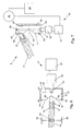
- eine Explosionsdarstellung eines Lenkstockschalters mit einem integrierten, verrastbaren Blinkerschalter, dem eine erfindungsgemäße Rückstelleinrichtung zugeordnet ist,
- Fig.2
- eine vereinfachte Schnittdarstellung der Einzelheit II gemäß Fig. 1,
- Fig.3
- die Darstellung der Einzelheit II nach Fig. 2 in einer anderen Stellung des Schalthebels,
- Fig.4
- die Darstellung der Einzelheit II nach Fig. 3 in einer weiteren Stellung des Schalthebels,
- Fig.5
- eine erste alternative Ausgestaltung der Einzelheit II gemäß Fig. 1 in einer vereinfachten Schnittdarstellung,
- Fig.6
- eine zweite alternative Ausgestaltung der Einzelheit II gemäß Fig. 1 in einer vereinfachten Schnittdarstellung und
- Fig.7
- eine dritte alternative Ausgestaltung der Einzelheit II gemäß Fig. 1 in einer vereinfachten Schnittdarstellung.
- Fig.1
- 2 shows an exploded view of a steering column switch with an integrated, latchable indicator switch, to which a reset device according to the invention is assigned,
- Fig.2
- a simplified sectional view of the detail II of FIG. 1,
- Figure 3
- the representation of the detail II of FIG. 2 in a different position of the shift lever,
- Figure 4
- the representation of the detail II of FIG. 3 in a further position of the shift lever,
- Figure 5
- 1 shows a first alternative embodiment of the detail II according to FIG. 1 in a simplified sectional illustration,
- Figure 6
- a second alternative embodiment of the detail II of FIG. 1 in a simplified sectional view and
- Figure 7
- a third alternative embodiment of the detail II of FIG. 1 in a simplified sectional view.
Der Lenkstockschalter umfasst ein aus einem Gehäuseoberteil 1
und einem Gehäuseunterteil 2 zusammengesetztes Gehäuse, wobei
an dem Gehäuseunterteil 2 eine zylindrische Ausnehmung 3 zur
Befestigung des Lenkstockschalters an einem nicht dargestellten
Mantelrohr eines Kraftfahrzeuges ausgeformt ist. Im weiteren
umfasst das Gehäuseunterteil 2 randseitige Klipsarme 4,
die beim Zusammenfügen des Gehäuseunterteils 2 und des Gehäuseoberteils
1 in korrespondierende Klipsöffnungen 5 des Gehäuseoberteils
1 eingreifen, sowie nicht dargestellte Zentrieröffnungen,
in die entsprechende Zentrieransätze 7 des
Gehäuseoberteils 1 eingesetzt werden. Schließlich ist dem Gehäuseunterteil
2 eine Leiterplatte 8 zugeordnet, die mit einem
Bordnetz sowie einem Bordrechner 32 des Kraftfahrzeuges
gekoppelt ist.The steering column switch comprises a housing
Die Leiterplatte 8 weist eine mit der Ausnehmung 3 des Gehäuseunterteils
2 sowie mit einer Bohrung 9 des Gehäuseoberteils
1 fluchtende zylindrische Öffnung 10 zur Durchführung einer
nicht dargestellten Lenksäule auf, deren freies Ende oberhalb
des Gehäuseoberteils 1 mit einem Lenkrad verbunden ist. Weiterhin
ist die Leiterplatte 8 mit Anschlüssen 11 für im wesentlichen
gegenüberliegende Schalter 6 versehen, von denen
lediglich einer dargestellt ist. Der als Blinkerschalter ausgebildete
verrastbare Schalter 6 weist einen Schalthebel 34
auf, der einen Durchbruch 12 des Gehäuseoberteils 1 durchragt
und der mittels leiterplattenseitige Durchgangsbohrungen 13
durchdringenden Verschraubungen an dem Gehäuseunterteil 2
festgelegt ist. Ferner ist die Leiterplatte 8 mit einem Zündschloss
verbunden, das in eine zwischen dem Gehäuseoberteil 1
und dem Gehäuseunterteil 2 gebildete Öffnung 14 eingesetzt
wird.The
Das das Gehäuseunterteil 2 randseitig übergreifende Gehäuseoberteil
1 weist eine Aussparung zur Aufnahme eines elektrischen
Leiters 16 einer elektrischen Verbindungseinrichtung 17
auf, die das Lenkrad über die Leiterplatte 8 mit dem Bordnetz
koppelt. Der flexibel ausgebildete Leiter 16 ist in mehreren
Windungen spiralförmig aufgewickelt und jeweils endseitig mit
einer Anschlusseinheit 18, 19 versehen, wobei die eine Anschlusseinheit
18 in eine Führungsausnehmung 20 des Gehäuseoberteils
1 eingesetzt und mit der Leiterplatte 8 gekoppelt
ist. Die andere Anschlusseinheit 19, die mit dem Lenkrad in
Verbindung steht, ist in eine Öffnung eines Deckels 22 eingesetzt,
der zur lenkradseitigen Befestigung einen Flansch 23
umfasst, an dem ein Ansatz 24 koaxial angeformt ist. Der
Flansch 23 des Deckels 22 überdeckt den Leiter 16, der sich
auf einem von dem Gehäuseoberteil 1 ausgebildeten Boden 25
abstützt. Der Ansatz 24 ist drehbar in den Boden 25 eingesetzt,
wobei der Ansatz 24 einen von dem Leiter 16 gebildeten
Freiraum 26 durchragt. Die seitliche Begrenzung des Leiters
16 wird von einer sich von einer Gehäuseoberseite zu dem Boden
25 erstreckenden Wandung des Gehäuseoberteils 1 gebildet.The upper housing part overlapping the edge of the
Um eine relative Änderung des Drehwinkels des Lenkrades gegenüber
dem Lenkstockschalter festzustellen, ist zwischen der
Verbindungseinrichtung 17 und dem Gehäuseoberteil 1 des Lenkstockschalters
ein Lenkwinkelsensor 29 angeordnet, der im wesentlichen
aus einem Rotor 30 und einem Stator 31 besteht,
wobei der Stator 31 über die Leiterplatte 8 mit dem Bordrechner
32 gekoppelt ist.Compared to a relative change in the angle of rotation of the steering wheel
the steering column switch is between the
Der Schalter 6 umfasst einen gehäuseseitig schwenkbar gelagerten
Schalthebel 34 mit einem als Rasthülse 35 ausgebildeten
Rastelement. An der Rasthülse 35 ist ein Bund 36 angeformt,
der zusammen mit einer Druckfeder 37 in eine Stufenbohrung
38 des Schalthebels 34 unverlierbar eingesetzt ist. The
Zur Verrastung des Schalthebels 34 in einer der Schaltstellungen
des Schalters 6 wirkt die Rasthülse 35 mit einer gehäuseseitigen
Rastkurve 39 zusammen. Die Rastkurve 39 ist im
wesentlichen V-förmig gestaltet, wobei an den Enden der
Schenkel 40 der V-Form kleine Nasen 41 ausgebildet sind und
jede der Nasen 41 den Schalthebel 34 in einer seiner verrasteten
Schaltstellungen hält. Um die Verrastung 56 des
Schalthebels 34 aufzuheben, ist der Rastkurve 39 eine Verstelleinrichtung
42 zugeordnet. Damit der Schalthebel 34
stets in seine nicht verrastete Stellung zurückkehrt, ist an
seinem Drehpunkt 57 eine Drehschenkelfeder 58 angeordnet, deren
Schenkel 59 einen gehäusefesten Anschlag 60 sowie eine
dem Schalthebel 34 zugeordnete Nase 61 umgreifen. Beim Verschwenken
des Schalthebels 34 in eine verrastete Schaltstellung,
wird die Drehschenkelfeder 58 gespannt und verschwenkt
den Schalthebel 34 beim Aufheben der Verrastung 56 in seine
Ausganglage. Ferner sind dem Schalthebel 34 gehäusefeste Anschläge
62 zugeordnet, die sein Verschwenken über eine vorbestimmte
Endlage hinaus verhindern.To lock the
Die Rastkurve 39 ist zwischen Gehäusewänden 43 geführt, an
deren freien Enden Anschläge 44 ausgebildet sind. In die
Rückwand 45 der Rastkurve 39 ist eine metallische Platte 46
eingesetzt, die mit einem Elektromagneten 47 der Verstelleinrichtung
42 zusammenwirkt. Zwischen der Rückwand 45 der Rastkurve
39 und der korrespondierenden Gehäusewand 48, an der
der Elektromagnet 47 befestigt ist, stützen sich Druckfedern
49 ab, die die Rastkurve 39 gegen die Anschläge 44 drücken.
In dieser Stellung der Rastkurve 39 kann der Schalthebel 34
in eine verrastete Stellung verschwenkt werden, in der die
Rasthülse 35 die zugeordnete Nase 41 der Rastkurve 39 hintergreift.
Zum Aufheben der Verrastung 56 in Abhängigkeit von
der Drehrichtung des Lenkrades erfasst der Bordrechner 32 die
Daten des Lenkwinkelsensors 29 und spricht den Elektromagneten
47 an, der daraufhin die Platte 46 mitsamt der Rastkurve
39 entgegen der Wirkung der Druckfedern 49 anzieht, bis die
Platte 46 auf dem Elektromagneten 47 zur Anlage kommt. Hierbei
entfernt sich die Nase 41 der Rastkurve 39 hinter die
Rasthülse 35 des Schalthebels 34 und dieser verschwenkt
zwangsgesteuert in die nicht verrastete Stellung, in der die
Rasthülse 35 in einem unteren Scheitelpunkt 50 der Rastkurve
39 einliegt. Nach einer vorgegebenen Zeitspanne oder nachdem
der Bordrechner 32 registriert hat, dass sich der Schalthebel
34 in keiner der verrasteten Schaltstellungen befindet, beendet
der Rechner die Stromzufuhr zu dem Elektromagneten 47 und
die Rastkurve 39 gelangt unter der Wirkung der Druckfedern 49
wieder an die Anschläge 44 der Gehäusewände 43.The
In einer alternativen Ausführung ist den gegenüberliegenden
Seitenwänden 54 der Rastkurve 39 jeweils eine metallische
Platte 46 zugeordnet und an den seitlichen Gehäusewänden 43
ist jeweils ein zu einer Platte 46 korrespondierender Elektromagnet
47 befestigt, wobei zwischen dem Elektromagneten 47
und der zugeordnete Seitenwand 54 vorgespannte Druckfedern 49
angeordnet sind. Die Rastkurve 39 ist mittels einer Führung
55 im wesentlichen senkrecht zu der Längsachse des Schalthebels
34 beweglich zwischen den seitlichen Gehäusewänden 43
gelagert. Befindet sich der Schalthebel 34 in einer der verrasteten
Schaltstellungen des Schalters 6, in der die Rasthülse
35 die zugeordnete Nase 41 der Rastkurve 39 hintergreift
und soll die Verrastung 56 aufgehoben werden, so
spricht der Bordrechner 32 den Elektromagneten 47 an, der
sich auf der der Verrastung 56 zugeordneten Seite des Schalters
6 befindet. Daraufhin zieht der Elektromagnet 47 die
Platte 46 und somit auch die Rastkurve 39 entgegen der Wirkung
der zugeordneten Druckfedern 49 an und die Rasthülse 35
gleitet zwangsgesteuert über die Nase 41 und dann auf dem
entsprechenden Schenkel 40 der Rastkurve 39 in eine nicht
verrastete Position, in der sie im Scheitelpunkt 50 in der
Rastkurve 39 einliegt. Nach dem Aufheben der Verrastung 56
unterbricht der Bordrechner 32 die Stromzufuhr zu dem Elektromagnet
47 und die Rastkurve 39 kehrt unter der Wirkung der
Druckfedern 49 in ihre Ausgangslage zurück, in der sie zwischen
den entsprechend ausgelegten Druckfedern 37 gehalten
wird.In an alternative version is the
Bei einer weiteren alternativen Ausgestaltung umfasst die
Verstelleinrichtung 42 einen Elektromotor 51, der zum einen
mit einem Getriebe 52 und zum anderen mit dem Bordrechner 32
gekoppelt ist. Das Getriebe 52 steht über eine Gewindestange
53 mit der Rastkurve 39 in Verbindung, wobei in die Rückwand
45 der Rastkurve 39 ein Gewinde für die Gewindestange 53 eingelassen
ist. Bei einer entsprechenden Beaufschlagung des
Elektromotors 51 durch den Bordrechner 32 bewegt dieser die
Rastkurve 39 im wesentlichen parallel zur Längsachse des
Schalthebels 34 kontinuierlich von demselben weg, bis die
Rasthülse 35 über die entsprechende Nase 41 der Rastkurve 39
gleitet und die Verrastung 56 aufgehoben ist. Anschließend
wird der Elektromotor 51 rechnergesteuert in eine umgekehrte
Drehrichtung versetzt, worauf er die Rastkurve 39 wieder in
Richtung des Schalthebels 34 transportiert, der dann durch
entsprechendes Verschwenken eine verrastete Schaltstellung
einnehmen kann. In a further alternative embodiment, the
Die Gewindestange 53 der Verstelleinrichtung 42 kann auch in
eine Seitenwand 54 der Rastkurve 39 eingesetzt werden, wobei
sowohl das Getriebe 52 als auch der Elektromotor 51 der korrespondierenden
seitlichen Gehäusewand 43 zugeordnet werden.
Der von dem Bordrechner 32 angesprochene Elektromotor 51 bewegt
bei dieser Anordnung die Rastkurve 39 in der Führung 55
im wesentlichen senkrecht zur Längsachse des Schalthebels 34.The threaded
Im Weiteren sind zwei gegenüberliegende gehäusefeste Rippen
63 angedeutet, die auf eine in den Schalthebel 34 eingesetzte
Druckfeder 64 wirken. Beim Verschwenken des Schalthebels 34
wird die Druckfeder 64 durch die entsprechende Rippe 63 vorgespannt.
Wird die Verrastung des Schalthebels 34 aufgehoben,
kehrt dieser aufgrund des Zusammenwirkens von vorgespannter
Druckfeder 64 und entsprechender Rippe 63 in seine Ausgangslage
zurück. In addition, there are two opposite ribs fixed to the
- 1.1.
- GehäuseoberteilHousing top
- 2.Second
- GehäuseunterteilHousing bottom
- 3.Third
- Ausnehmungrecess
- 4.4th
- Klipsarmclip arm
- 5.5th
- KlipsöffnungKlipsöffnung
- 6.6th
- Schalterswitch
- 7.7th
- ZentrieransatzSpigot
- 8.8th.
- Leiterplattecircuit board
- 9.9th
- Bohrungdrilling
- 10.10th
- Öffnungopening
- 11.11th
- Anschlussconnection
- 12.12th
- Durchbruchbreakthrough
- 13.13th
- DurchgangsbohrungThrough Hole
- 14.14th
- Öffnungopening
- 15. 16.15th 16th
- Leiterladder
- 17.17th
- Verbindungseinrichtungconnecting device
- 18.18th
- Anschlusseinheitconnection unit
- 19.19th
- Anschlusseinheitconnection unit
- 20.20th
- Führungsausnehmungguide recess
- 21. 22.21st 22nd
- Deckelcover
- 23.23rd
- Flanschflange
- 24.24th
- Ansatzapproach
- 25.25th
- Bodenground
- 26.26th
- Freiraumfree space
- 27. 28. 29.27th 28th 29th
- LenkwinkelsensorSteering angle sensor
- 30.30th
- Rotorrotor
- 31.31st
- Statorstator
- 32.32nd
- Bordrechneron-board computer
- 33. 34.33rd 34th
- Schalthebelgear lever
- 35.35th
- Rasthülselocking sleeve
- 36.36th
- BundFederation
- 37.37th
- Druckfedercompression spring
- 38.38th
- Stufenbohrungstepped bore
- 39.39th
- Rastkurvelocking curve
- 40.40th
- Schenkelleg
- 41.41st
- Nasenose
- 42.42nd
- Verstelleinrichtungadjustment
- 43.43rd
- Gehäusewandhousing wall
- 44.44th
- Anschlagattack
- 45.45th
- Rückwandrear wall
- 46.46th
- Platteplate
- 47.47th
- Elektromagnetelectromagnet
- 48.48th
- Gehäusewandhousing wall
- 49.49th
- Druckfedercompression spring
- 50.50th
- Scheitelpunktvertex
- 51.51st
- Elektromotorelectric motor
- 52.52nd
- Getriebetransmission
- 53.53rd
- Gewindestangethreaded rod
- 54.54th
- SeitenwandSide wall
- 55.55th
- Führungguide
- 56.56th
- Verrastunglatching
- 57.57th
- Drehpunktpivot point
- 58.58th
- DrehschenkelfederTorsion spring
- 59.59th
- Schenkelleg
- 60.60th
- Anschlagattack
- 61.61st
- Nasenose
- 62.62nd
- Anschlagattack
- 63.63rd
- Ripperib
- 64.64th
- Druckfedercompression spring
Claims (17)
Priority Applications (1)
| Application Number | Priority Date | Filing Date | Title |
|---|---|---|---|
| EP08005405A EP1939039A1 (en) | 2000-08-03 | 2001-07-25 | Switch reset device for vehicle |
Applications Claiming Priority (2)
| Application Number | Priority Date | Filing Date | Title |
|---|---|---|---|
| DE2000137760 DE10037760A1 (en) | 2000-08-03 | 2000-08-03 | Reset device for a switch of a motor vehicle |
| DE10037760 | 2000-08-03 |
Related Child Applications (1)
| Application Number | Title | Priority Date | Filing Date |
|---|---|---|---|
| EP08005405A Division EP1939039A1 (en) | 2000-08-03 | 2001-07-25 | Switch reset device for vehicle |
Publications (3)
| Publication Number | Publication Date |
|---|---|
| EP1177942A2 true EP1177942A2 (en) | 2002-02-06 |
| EP1177942A3 EP1177942A3 (en) | 2006-04-26 |
| EP1177942B1 EP1177942B1 (en) | 2008-09-03 |
Family
ID=7651136
Family Applications (2)
| Application Number | Title | Priority Date | Filing Date |
|---|---|---|---|
| EP08005405A Withdrawn EP1939039A1 (en) | 2000-08-03 | 2001-07-25 | Switch reset device for vehicle |
| EP01117983A Expired - Lifetime EP1177942B1 (en) | 2000-08-03 | 2001-07-25 | Switch reset device for vehicle |
Family Applications Before (1)
| Application Number | Title | Priority Date | Filing Date |
|---|---|---|---|
| EP08005405A Withdrawn EP1939039A1 (en) | 2000-08-03 | 2001-07-25 | Switch reset device for vehicle |
Country Status (2)
| Country | Link |
|---|---|
| EP (2) | EP1939039A1 (en) |
| DE (2) | DE10037760A1 (en) |
Cited By (9)
| Publication number | Priority date | Publication date | Assignee | Title |
|---|---|---|---|---|
| EP1528366A1 (en) * | 2003-10-29 | 2005-05-04 | Wen-Wei Su | Position encoder with colour coded scale |
| EP1219496A3 (en) * | 2000-12-28 | 2006-05-03 | Valeo Schalter und Sensoren GmbH | Device for actuating the flashing lights of a vehcle |
| DE102010007424A1 (en) * | 2010-02-10 | 2011-08-11 | Valeo Schalter und Sensoren GmbH, 74321 | Lever resetting device for resetting lever movable around drag axis from deflected position into starting position, comprises cams, which are connected with lever in non-rotatable manner |
| WO2016113282A1 (en) * | 2015-01-14 | 2016-07-21 | Leopold Kostal Gmbh & Co Kg | Steering column switch for a motor vehicle |
| EP3546289A1 (en) * | 2018-03-22 | 2019-10-02 | Mazda Motor Corporation | Switching device for vehicle headlight, headlight system, vehicle, method of switching modes of vehicle headlight, and computer program product |
| DE102020102995B3 (en) * | 2020-02-06 | 2021-03-04 | Audi Aktiengesellschaft | STEERING COLUMN SWITCH AND METHOD OF CONTROLLING AN ELECTROMAGNET IN A STEERING COLUMN SWITCH |
| WO2021216438A1 (en) * | 2020-04-20 | 2021-10-28 | Strattec Security Corporation | Cancellation device for an automotive feature |
| WO2022199802A1 (en) | 2021-03-23 | 2022-09-29 | Merit Automotive Electronics Systems S.L.U. | Rotary switch assembly with a controllable cancelling mechanism |
| WO2022248058A1 (en) | 2021-05-28 | 2022-12-01 | Merit Automotive Electronics Systems S.L.U. | Stalk switch assembly with a controllable releasing mechanism |
Families Citing this family (7)
| Publication number | Priority date | Publication date | Assignee | Title |
|---|---|---|---|---|
| DE102007036633A1 (en) | 2007-08-03 | 2009-02-05 | Man Nutzfahrzeuge Ag | Device for activation and deactivation of direction indicators in motor vehicle, has actuating devices for indicating direction of travel, where central on-board computer processes signal data from actuation devices |
| DE102011110701A1 (en) | 2011-08-16 | 2013-02-21 | GM Global Technology Operations LLC (n. d. Gesetzen des Staates Delaware) | adjustment |
| EP3356183A4 (en) * | 2015-09-27 | 2019-05-22 | Djerroud, Idris | Lighting and signaling switch with semi-automatic switching from high beams to low beams |
| DE102018115330A1 (en) * | 2018-06-26 | 2020-01-02 | Valeo Schalter Und Sensoren Gmbh | Reset device for a steering column arm for motor vehicles |
| DE102018119801A1 (en) * | 2018-08-15 | 2020-02-20 | Valeo Schalter Und Sensoren Gmbh | Reset device for a direction indicator of a vehicle, direction indicator and vehicle |
| US20220072994A1 (en) * | 2018-12-04 | 2022-03-10 | Strattec Security Corporation | Cancellation device for an automotive feature |
| DE102022105240A1 (en) | 2022-03-07 | 2023-09-07 | Bayerische Motoren Werke Aktiengesellschaft | DIRECTION INDICATOR AND METHOD OF INDICATION OF DIRECTION FOR A MOTOR VEHICLE |
Citations (3)
| Publication number | Priority date | Publication date | Assignee | Title |
|---|---|---|---|---|
| DE2725805C2 (en) | 1977-06-08 | 1984-02-23 | Robert Bosch Gmbh, 7000 Stuttgart | Device for switching off a direction indicator in a motor vehicle after cornering |
| DE2721879C3 (en) | 1977-05-14 | 1985-11-14 | SWF Auto-Electric GmbH, 7120 Bietigheim-Bissingen | Switching device for controlling the flashing lamps in motor vehicles |
| DE19758288A1 (en) | 1997-12-31 | 1999-07-01 | Itt Mfg Enterprises Inc | Turning direction method for vehicles |
Family Cites Families (6)
| Publication number | Priority date | Publication date | Assignee | Title |
|---|---|---|---|---|
| DE720718C (en) * | 1940-12-04 | 1942-05-13 | Herbert Becker | Switching device for direction indicators of motor vehicles with automatic downshift of the manual lever |
| US4125827A (en) * | 1973-09-17 | 1978-11-14 | Roudebush Jr Robert D | Automatically cancelling turn signal |
| JPS5720424Y2 (en) * | 1975-11-14 | 1982-05-01 | ||
| JPH0447874Y2 (en) * | 1985-07-24 | 1992-11-11 | ||
| US4900946A (en) * | 1988-06-03 | 1990-02-13 | Navistar International Transportation Corp. | Multi-function switch for automotive vehicles |
| JPH0422335U (en) * | 1990-06-19 | 1992-02-25 |
-
2000
- 2000-08-03 DE DE2000137760 patent/DE10037760A1/en not_active Withdrawn
-
2001
- 2001-07-25 EP EP08005405A patent/EP1939039A1/en not_active Withdrawn
- 2001-07-25 EP EP01117983A patent/EP1177942B1/en not_active Expired - Lifetime
- 2001-07-25 DE DE50114277T patent/DE50114277D1/en not_active Expired - Fee Related
Patent Citations (3)
| Publication number | Priority date | Publication date | Assignee | Title |
|---|---|---|---|---|
| DE2721879C3 (en) | 1977-05-14 | 1985-11-14 | SWF Auto-Electric GmbH, 7120 Bietigheim-Bissingen | Switching device for controlling the flashing lamps in motor vehicles |
| DE2725805C2 (en) | 1977-06-08 | 1984-02-23 | Robert Bosch Gmbh, 7000 Stuttgart | Device for switching off a direction indicator in a motor vehicle after cornering |
| DE19758288A1 (en) | 1997-12-31 | 1999-07-01 | Itt Mfg Enterprises Inc | Turning direction method for vehicles |
Cited By (11)
| Publication number | Priority date | Publication date | Assignee | Title |
|---|---|---|---|---|
| EP1219496A3 (en) * | 2000-12-28 | 2006-05-03 | Valeo Schalter und Sensoren GmbH | Device for actuating the flashing lights of a vehcle |
| EP1528366A1 (en) * | 2003-10-29 | 2005-05-04 | Wen-Wei Su | Position encoder with colour coded scale |
| DE102010007424A1 (en) * | 2010-02-10 | 2011-08-11 | Valeo Schalter und Sensoren GmbH, 74321 | Lever resetting device for resetting lever movable around drag axis from deflected position into starting position, comprises cams, which are connected with lever in non-rotatable manner |
| DE102010007424B4 (en) * | 2010-02-10 | 2019-09-12 | Valeo Schalter Und Sensoren Gmbh | Lever reset mechanism |
| WO2016113282A1 (en) * | 2015-01-14 | 2016-07-21 | Leopold Kostal Gmbh & Co Kg | Steering column switch for a motor vehicle |
| US10207732B2 (en) | 2015-01-14 | 2019-02-19 | Leopold Kostal Gmbh & Co. Kg | Steering column switch for a motor vehicle |
| EP3546289A1 (en) * | 2018-03-22 | 2019-10-02 | Mazda Motor Corporation | Switching device for vehicle headlight, headlight system, vehicle, method of switching modes of vehicle headlight, and computer program product |
| DE102020102995B3 (en) * | 2020-02-06 | 2021-03-04 | Audi Aktiengesellschaft | STEERING COLUMN SWITCH AND METHOD OF CONTROLLING AN ELECTROMAGNET IN A STEERING COLUMN SWITCH |
| WO2021216438A1 (en) * | 2020-04-20 | 2021-10-28 | Strattec Security Corporation | Cancellation device for an automotive feature |
| WO2022199802A1 (en) | 2021-03-23 | 2022-09-29 | Merit Automotive Electronics Systems S.L.U. | Rotary switch assembly with a controllable cancelling mechanism |
| WO2022248058A1 (en) | 2021-05-28 | 2022-12-01 | Merit Automotive Electronics Systems S.L.U. | Stalk switch assembly with a controllable releasing mechanism |
Also Published As
| Publication number | Publication date |
|---|---|
| EP1177942B1 (en) | 2008-09-03 |
| EP1177942A3 (en) | 2006-04-26 |
| DE10037760A1 (en) | 2002-02-14 |
| DE50114277D1 (en) | 2008-10-16 |
| EP1939039A1 (en) | 2008-07-02 |
Similar Documents
| Publication | Publication Date | Title |
|---|---|---|
| DE4343339C2 (en) | Motor vehicle door lock with child safety device | |
| DE19635414C2 (en) | Lock, especially for vehicle doors or the like | |
| EP1177942A2 (en) | Switch reset device for vehicle | |
| DE10065569B4 (en) | Device for opening and closing motor vehicle locks | |
| EP1848903B1 (en) | Electric circuit arrangement for a motor vehicle | |
| EP1225290B1 (en) | Motor vehicle door lock | |
| EP3469175B1 (en) | Door handle module for a motor vehicle | |
| EP2539188B1 (en) | Steering locking device for a vehicle | |
| DE102006029774A1 (en) | Gripping device for actuating lock for opening and/or closing of e.g. door, has electronic unit for comfortable handling of gripping device, and arranged in hollow space or U-shaped projection that is present in movable gripping unit | |
| EP1279576B1 (en) | Ignition switch system for a motor vehicle | |
| DE3905698C1 (en) | Device for locking the gear shift lever of a motor vehicle | |
| DE4446613A1 (en) | Steering wheel lock for motor vehicle | |
| DE19957046A1 (en) | Electronic lock for automobile central locking system verifies correct insertion of electronically coded key and coded operating signal provided by key before lock can be operated | |
| EP1143093B1 (en) | Motor vehicle door lock with elastic movable coupling element | |
| DE4005641C2 (en) | ||
| DE19547724A1 (en) | Servo operated door lock esp. for automobile | |
| EP0432469A2 (en) | Vehicle door lock | |
| DE102017108752A1 (en) | Lock with a closing device for a motor vehicle | |
| EP2034112A1 (en) | Motor vehicle door lock | |
| EP1418298B1 (en) | Closing assistance for locking a vehicle door | |
| EP3227147B1 (en) | Locking device for a vehicle | |
| EP3819449A1 (en) | Motor vehicle lock | |
| DE10002776A1 (en) | Electromotive actuator for a motor vehicle lock | |
| DE10107992A1 (en) | Motor vehicle ignition lock system has locking element in locking device coupled to handle so locking element can be moved between locking/release positions during/after handle movement | |
| DE4221671C2 (en) | Actuator for unlocking a locking device |
Legal Events
| Date | Code | Title | Description |
|---|---|---|---|
| PUAI | Public reference made under article 153(3) epc to a published international application that has entered the european phase |
Free format text: ORIGINAL CODE: 0009012 |
|
| AK | Designated contracting states |
Kind code of ref document: A2 Designated state(s): AT BE CH CY DE DK ES FI FR GB GR IE IT LI LU MC NL PT SE TR |
|
| AX | Request for extension of the european patent |
Free format text: AL;LT;LV;MK;RO;SI |
|
| PUAL | Search report despatched |
Free format text: ORIGINAL CODE: 0009013 |
|
| AK | Designated contracting states |
Kind code of ref document: A3 Designated state(s): AT BE CH CY DE DK ES FI FR GB GR IE IT LI LU MC NL PT SE TR |
|
| AX | Request for extension of the european patent |
Extension state: AL LT LV MK RO SI |
|
| 17P | Request for examination filed |
Effective date: 20061006 |
|
| 17Q | First examination report despatched |
Effective date: 20061102 |
|
| AKX | Designation fees paid |
Designated state(s): DE FR GB |
|
| 17Q | First examination report despatched |
Effective date: 20061102 |
|
| GRAP | Despatch of communication of intention to grant a patent |
Free format text: ORIGINAL CODE: EPIDOSNIGR1 |
|
| GRAS | Grant fee paid |
Free format text: ORIGINAL CODE: EPIDOSNIGR3 |
|
| GRAA | (expected) grant |
Free format text: ORIGINAL CODE: 0009210 |
|
| AK | Designated contracting states |
Kind code of ref document: B1 Designated state(s): DE FR GB |
|
| REG | Reference to a national code |
Ref country code: GB Ref legal event code: FG4D Free format text: NOT ENGLISH |
|
| REF | Corresponds to: |
Ref document number: 50114277 Country of ref document: DE Date of ref document: 20081016 Kind code of ref document: P |
|
| PLBE | No opposition filed within time limit |
Free format text: ORIGINAL CODE: 0009261 |
|
| STAA | Information on the status of an ep patent application or granted ep patent |
Free format text: STATUS: NO OPPOSITION FILED WITHIN TIME LIMIT |
|
| 26N | No opposition filed |
Effective date: 20090604 |
|
| GBPC | Gb: european patent ceased through non-payment of renewal fee |
Effective date: 20090725 |
|
| REG | Reference to a national code |
Ref country code: FR Ref legal event code: ST Effective date: 20100331 |
|
| PG25 | Lapsed in a contracting state [announced via postgrant information from national office to epo] |
Ref country code: FR Free format text: LAPSE BECAUSE OF NON-PAYMENT OF DUE FEES Effective date: 20090731 |
|
| PG25 | Lapsed in a contracting state [announced via postgrant information from national office to epo] |
Ref country code: GB Free format text: LAPSE BECAUSE OF NON-PAYMENT OF DUE FEES Effective date: 20090725 |
|
| PG25 | Lapsed in a contracting state [announced via postgrant information from national office to epo] |
Ref country code: DE Free format text: LAPSE BECAUSE OF NON-PAYMENT OF DUE FEES Effective date: 20100202 |