EP1176648A2 - Process for the preparation of battery - Google Patents
Process for the preparation of battery Download PDFInfo
- Publication number
- EP1176648A2 EP1176648A2 EP01118350A EP01118350A EP1176648A2 EP 1176648 A2 EP1176648 A2 EP 1176648A2 EP 01118350 A EP01118350 A EP 01118350A EP 01118350 A EP01118350 A EP 01118350A EP 1176648 A2 EP1176648 A2 EP 1176648A2
- Authority
- EP
- European Patent Office
- Prior art keywords
- electrode lead
- lead member
- battery case
- battery
- positive electrode
- Prior art date
- Legal status (The legal status is an assumption and is not a legal conclusion. Google has not performed a legal analysis and makes no representation as to the accuracy of the status listed.)
- Withdrawn
Links
- 238000002360 preparation method Methods 0.000 title claims abstract description 17
- 238000000034 method Methods 0.000 title claims abstract description 12
- 229920005989 resin Polymers 0.000 claims description 8
- 239000011347 resin Substances 0.000 claims description 8
- 238000007789 sealing Methods 0.000 claims description 4
- -1 polyethylene terephthalate Polymers 0.000 description 9
- 239000008151 electrolyte solution Substances 0.000 description 8
- 239000004698 Polyethylene Substances 0.000 description 7
- 229910052782 aluminium Inorganic materials 0.000 description 7
- WHXSMMKQMYFTQS-UHFFFAOYSA-N Lithium Chemical group [Li] WHXSMMKQMYFTQS-UHFFFAOYSA-N 0.000 description 6
- XAGFODPZIPBFFR-UHFFFAOYSA-N aluminium Chemical compound [Al] XAGFODPZIPBFFR-UHFFFAOYSA-N 0.000 description 6
- 229910052744 lithium Inorganic materials 0.000 description 6
- 239000007787 solid Substances 0.000 description 6
- 239000011888 foil Substances 0.000 description 5
- 239000000203 mixture Substances 0.000 description 5
- 239000005518 polymer electrolyte Substances 0.000 description 5
- 229920000139 polyethylene terephthalate Polymers 0.000 description 4
- 239000005020 polyethylene terephthalate Substances 0.000 description 4
- 238000004080 punching Methods 0.000 description 4
- WEVYAHXRMPXWCK-UHFFFAOYSA-N Acetonitrile Chemical compound CC#N WEVYAHXRMPXWCK-UHFFFAOYSA-N 0.000 description 3
- OKTJSMMVPCPJKN-UHFFFAOYSA-N Carbon Chemical compound [C] OKTJSMMVPCPJKN-UHFFFAOYSA-N 0.000 description 3
- ZMXDDKWLCZADIW-UHFFFAOYSA-N N,N-Dimethylformamide Chemical compound CN(C)C=O ZMXDDKWLCZADIW-UHFFFAOYSA-N 0.000 description 3
- 239000003792 electrolyte Substances 0.000 description 3
- 229910000625 lithium cobalt oxide Inorganic materials 0.000 description 3
- BFZPBUKRYWOWDV-UHFFFAOYSA-N lithium;oxido(oxo)cobalt Chemical compound [Li+].[O-][Co]=O BFZPBUKRYWOWDV-UHFFFAOYSA-N 0.000 description 3
- 229920000573 polyethylene Polymers 0.000 description 3
- 229920000642 polymer Polymers 0.000 description 3
- 239000007774 positive electrode material Substances 0.000 description 3
- 229920005992 thermoplastic resin Polymers 0.000 description 3
- SZUVGFMDDVSKSI-WIFOCOSTSA-N (1s,2s,3s,5r)-1-(carboxymethyl)-3,5-bis[(4-phenoxyphenyl)methyl-propylcarbamoyl]cyclopentane-1,2-dicarboxylic acid Chemical compound O=C([C@@H]1[C@@H]([C@](CC(O)=O)([C@H](C(=O)N(CCC)CC=2C=CC(OC=3C=CC=CC=3)=CC=2)C1)C(O)=O)C(O)=O)N(CCC)CC(C=C1)=CC=C1OC1=CC=CC=C1 SZUVGFMDDVSKSI-WIFOCOSTSA-N 0.000 description 2
- YEJRWHAVMIAJKC-UHFFFAOYSA-N 4-Butyrolactone Chemical compound O=C1CCCO1 YEJRWHAVMIAJKC-UHFFFAOYSA-N 0.000 description 2
- RYGMFSIKBFXOCR-UHFFFAOYSA-N Copper Chemical compound [Cu] RYGMFSIKBFXOCR-UHFFFAOYSA-N 0.000 description 2
- OIFBSDVPJOWBCH-UHFFFAOYSA-N Diethyl carbonate Chemical compound CCOC(=O)OCC OIFBSDVPJOWBCH-UHFFFAOYSA-N 0.000 description 2
- XTHFKEDIFFGKHM-UHFFFAOYSA-N Dimethoxyethane Chemical compound COCCOC XTHFKEDIFFGKHM-UHFFFAOYSA-N 0.000 description 2
- IAZDPXIOMUYVGZ-UHFFFAOYSA-N Dimethylsulphoxide Chemical compound CS(C)=O IAZDPXIOMUYVGZ-UHFFFAOYSA-N 0.000 description 2
- KMTRUDSVKNLOMY-UHFFFAOYSA-N Ethylene carbonate Chemical compound O=C1OCCO1 KMTRUDSVKNLOMY-UHFFFAOYSA-N 0.000 description 2
- XEEYBQQBJWHFJM-UHFFFAOYSA-N Iron Chemical compound [Fe] XEEYBQQBJWHFJM-UHFFFAOYSA-N 0.000 description 2
- PXHVJJICTQNCMI-UHFFFAOYSA-N Nickel Chemical compound [Ni] PXHVJJICTQNCMI-UHFFFAOYSA-N 0.000 description 2
- WYURNTSHIVDZCO-UHFFFAOYSA-N Tetrahydrofuran Chemical compound C1CCOC1 WYURNTSHIVDZCO-UHFFFAOYSA-N 0.000 description 2
- GWEVSGVZZGPLCZ-UHFFFAOYSA-N Titan oxide Chemical compound O=[Ti]=O GWEVSGVZZGPLCZ-UHFFFAOYSA-N 0.000 description 2
- XRWSZZJLZRKHHD-WVWIJVSJSA-N asunaprevir Chemical compound O=C([C@@H]1C[C@H](CN1C(=O)[C@@H](NC(=O)OC(C)(C)C)C(C)(C)C)OC1=NC=C(C2=CC=C(Cl)C=C21)OC)N[C@]1(C(=O)NS(=O)(=O)C2CC2)C[C@H]1C=C XRWSZZJLZRKHHD-WVWIJVSJSA-N 0.000 description 2
- 229940126543 compound 14 Drugs 0.000 description 2
- 229940125961 compound 24 Drugs 0.000 description 2
- 150000001875 compounds Chemical class 0.000 description 2
- 238000011109 contamination Methods 0.000 description 2
- 239000011889 copper foil Substances 0.000 description 2
- IEJIGPNLZYLLBP-UHFFFAOYSA-N dimethyl carbonate Chemical compound COC(=O)OC IEJIGPNLZYLLBP-UHFFFAOYSA-N 0.000 description 2
- QXYJCZRRLLQGCR-UHFFFAOYSA-N dioxomolybdenum Chemical compound O=[Mo]=O QXYJCZRRLLQGCR-UHFFFAOYSA-N 0.000 description 2
- 229910002804 graphite Inorganic materials 0.000 description 2
- 239000010439 graphite Substances 0.000 description 2
- 229910003002 lithium salt Inorganic materials 0.000 description 2
- 159000000002 lithium salts Chemical class 0.000 description 2
- NUJOXMJBOLGQSY-UHFFFAOYSA-N manganese dioxide Chemical compound O=[Mn]=O NUJOXMJBOLGQSY-UHFFFAOYSA-N 0.000 description 2
- 238000004519 manufacturing process Methods 0.000 description 2
- 239000000463 material Substances 0.000 description 2
- 239000012528 membrane Substances 0.000 description 2
- 229910052751 metal Inorganic materials 0.000 description 2
- 239000002184 metal Substances 0.000 description 2
- 238000012986 modification Methods 0.000 description 2
- 230000004048 modification Effects 0.000 description 2
- 239000007773 negative electrode material Substances 0.000 description 2
- 239000011255 nonaqueous electrolyte Substances 0.000 description 2
- 239000011148 porous material Substances 0.000 description 2
- BHZCMUVGYXEBMY-UHFFFAOYSA-N trilithium;azanide Chemical compound [Li+].[Li+].[Li+].[NH2-] BHZCMUVGYXEBMY-UHFFFAOYSA-N 0.000 description 2
- XLYOFNOQVPJJNP-UHFFFAOYSA-N water Substances O XLYOFNOQVPJJNP-UHFFFAOYSA-N 0.000 description 2
- 238000004804 winding Methods 0.000 description 2
- LZDKZFUFMNSQCJ-UHFFFAOYSA-N 1,2-diethoxyethane Chemical compound CCOCCOCC LZDKZFUFMNSQCJ-UHFFFAOYSA-N 0.000 description 1
- WNXJIVFYUVYPPR-UHFFFAOYSA-N 1,3-dioxolane Chemical compound C1COCO1 WNXJIVFYUVYPPR-UHFFFAOYSA-N 0.000 description 1
- JWUJQDFVADABEY-UHFFFAOYSA-N 2-methyltetrahydrofuran Chemical compound CC1CCCO1 JWUJQDFVADABEY-UHFFFAOYSA-N 0.000 description 1
- 229910000733 Li alloy Inorganic materials 0.000 description 1
- 229910010226 Li2Mn2O4 Inorganic materials 0.000 description 1
- 229910000552 LiCF3SO3 Inorganic materials 0.000 description 1
- 229910010525 LiFe2O3 Inorganic materials 0.000 description 1
- 229910013131 LiN Inorganic materials 0.000 description 1
- 229910013398 LiN(SO2CF2CF3)2 Inorganic materials 0.000 description 1
- 229910013406 LiN(SO2CF3)2 Inorganic materials 0.000 description 1
- 229910003005 LiNiO2 Inorganic materials 0.000 description 1
- 229910001290 LiPF6 Inorganic materials 0.000 description 1
- 229910002097 Lithium manganese(III,IV) oxide Inorganic materials 0.000 description 1
- 229910015530 LixMO2 Inorganic materials 0.000 description 1
- 229910013263 LiyM2O4 Inorganic materials 0.000 description 1
- FXHOOIRPVKKKFG-UHFFFAOYSA-N N,N-Dimethylacetamide Chemical compound CN(C)C(C)=O FXHOOIRPVKKKFG-UHFFFAOYSA-N 0.000 description 1
- XBDQKXXYIPTUBI-UHFFFAOYSA-M Propionate Chemical compound CCC([O-])=O XBDQKXXYIPTUBI-UHFFFAOYSA-M 0.000 description 1
- 229910003092 TiS2 Inorganic materials 0.000 description 1
- KXKVLQRXCPHEJC-UHFFFAOYSA-N acetic acid trimethyl ester Natural products COC(C)=O KXKVLQRXCPHEJC-UHFFFAOYSA-N 0.000 description 1
- 239000011149 active material Substances 0.000 description 1
- 229910052793 cadmium Inorganic materials 0.000 description 1
- 229910052799 carbon Inorganic materials 0.000 description 1
- 239000003575 carbonaceous material Substances 0.000 description 1
- 230000001413 cellular effect Effects 0.000 description 1
- 150000004770 chalcogenides Chemical class 0.000 description 1
- 239000002131 composite material Substances 0.000 description 1
- 229920001940 conductive polymer Polymers 0.000 description 1
- 230000002950 deficient Effects 0.000 description 1
- 230000002708 enhancing effect Effects 0.000 description 1
- 238000010438 heat treatment Methods 0.000 description 1
- 150000002484 inorganic compounds Chemical class 0.000 description 1
- 229910010272 inorganic material Inorganic materials 0.000 description 1
- 229910052742 iron Inorganic materials 0.000 description 1
- 238000003698 laser cutting Methods 0.000 description 1
- 229910052745 lead Inorganic materials 0.000 description 1
- 229910001540 lithium hexafluoroarsenate(V) Inorganic materials 0.000 description 1
- MHCFAGZWMAWTNR-UHFFFAOYSA-M lithium perchlorate Chemical compound [Li+].[O-]Cl(=O)(=O)=O MHCFAGZWMAWTNR-UHFFFAOYSA-M 0.000 description 1
- 229910001486 lithium perchlorate Inorganic materials 0.000 description 1
- 229910001496 lithium tetrafluoroborate Inorganic materials 0.000 description 1
- HSFDLPWPRRSVSM-UHFFFAOYSA-M lithium;2,2,2-trifluoroacetate Chemical compound [Li+].[O-]C(=O)C(F)(F)F HSFDLPWPRRSVSM-UHFFFAOYSA-M 0.000 description 1
- QSZMZKBZAYQGRS-UHFFFAOYSA-N lithium;bis(trifluoromethylsulfonyl)azanide Chemical compound [Li+].FC(F)(F)S(=O)(=O)[N-]S(=O)(=O)C(F)(F)F QSZMZKBZAYQGRS-UHFFFAOYSA-N 0.000 description 1
- 239000007769 metal material Substances 0.000 description 1
- 239000012982 microporous membrane Substances 0.000 description 1
- 229910052759 nickel Inorganic materials 0.000 description 1
- 150000002894 organic compounds Chemical class 0.000 description 1
- 239000003960 organic solvent Substances 0.000 description 1
- 239000002798 polar solvent Substances 0.000 description 1
- 229920000767 polyaniline Polymers 0.000 description 1
- 229920000867 polyelectrolyte Polymers 0.000 description 1
- RUOJZAUFBMNUDX-UHFFFAOYSA-N propylene carbonate Chemical compound CC1COC(=O)O1 RUOJZAUFBMNUDX-UHFFFAOYSA-N 0.000 description 1
- 229910052710 silicon Inorganic materials 0.000 description 1
- 239000002904 solvent Substances 0.000 description 1
- 239000010935 stainless steel Substances 0.000 description 1
- 229910001220 stainless steel Inorganic materials 0.000 description 1
- HXJUTPCZVOIRIF-UHFFFAOYSA-N sulfolane Chemical compound O=S1(=O)CCCC1 HXJUTPCZVOIRIF-UHFFFAOYSA-N 0.000 description 1
- YLQBMQCUIZJEEH-UHFFFAOYSA-N tetrahydrofuran Natural products C=1C=COC=1 YLQBMQCUIZJEEH-UHFFFAOYSA-N 0.000 description 1
- 229910052718 tin Inorganic materials 0.000 description 1
- 229910052723 transition metal Inorganic materials 0.000 description 1
- 229910000314 transition metal oxide Inorganic materials 0.000 description 1
- 150000003624 transition metals Chemical class 0.000 description 1
- TWQULNDIKKJZPH-UHFFFAOYSA-K trilithium;phosphate Chemical class [Li+].[Li+].[Li+].[O-]P([O-])([O-])=O TWQULNDIKKJZPH-UHFFFAOYSA-K 0.000 description 1
- DZKDPOPGYFUOGI-UHFFFAOYSA-N tungsten dioxide Inorganic materials O=[W]=O DZKDPOPGYFUOGI-UHFFFAOYSA-N 0.000 description 1
- 238000007666 vacuum forming Methods 0.000 description 1
- 229910052725 zinc Inorganic materials 0.000 description 1
Images


Classifications
-
- H—ELECTRICITY
- H01—ELECTRIC ELEMENTS
- H01M—PROCESSES OR MEANS, e.g. BATTERIES, FOR THE DIRECT CONVERSION OF CHEMICAL ENERGY INTO ELECTRICAL ENERGY
- H01M10/00—Secondary cells; Manufacture thereof
- H01M10/04—Construction or manufacture in general
- H01M10/0431—Cells with wound or folded electrodes
-
- H—ELECTRICITY
- H01—ELECTRIC ELEMENTS
- H01M—PROCESSES OR MEANS, e.g. BATTERIES, FOR THE DIRECT CONVERSION OF CHEMICAL ENERGY INTO ELECTRICAL ENERGY
- H01M50/00—Constructional details or processes of manufacture of the non-active parts of electrochemical cells other than fuel cells, e.g. hybrid cells
- H01M50/10—Primary casings; Jackets or wrappings
- H01M50/116—Primary casings; Jackets or wrappings characterised by the material
- H01M50/117—Inorganic material
- H01M50/119—Metals
-
- H—ELECTRICITY
- H01—ELECTRIC ELEMENTS
- H01M—PROCESSES OR MEANS, e.g. BATTERIES, FOR THE DIRECT CONVERSION OF CHEMICAL ENERGY INTO ELECTRICAL ENERGY
- H01M50/00—Constructional details or processes of manufacture of the non-active parts of electrochemical cells other than fuel cells, e.g. hybrid cells
- H01M50/10—Primary casings; Jackets or wrappings
- H01M50/116—Primary casings; Jackets or wrappings characterised by the material
- H01M50/121—Organic material
-
- H—ELECTRICITY
- H01—ELECTRIC ELEMENTS
- H01M—PROCESSES OR MEANS, e.g. BATTERIES, FOR THE DIRECT CONVERSION OF CHEMICAL ENERGY INTO ELECTRICAL ENERGY
- H01M50/00—Constructional details or processes of manufacture of the non-active parts of electrochemical cells other than fuel cells, e.g. hybrid cells
- H01M50/10—Primary casings; Jackets or wrappings
- H01M50/116—Primary casings; Jackets or wrappings characterised by the material
- H01M50/124—Primary casings; Jackets or wrappings characterised by the material having a layered structure
-
- H—ELECTRICITY
- H01—ELECTRIC ELEMENTS
- H01M—PROCESSES OR MEANS, e.g. BATTERIES, FOR THE DIRECT CONVERSION OF CHEMICAL ENERGY INTO ELECTRICAL ENERGY
- H01M50/00—Constructional details or processes of manufacture of the non-active parts of electrochemical cells other than fuel cells, e.g. hybrid cells
- H01M50/10—Primary casings; Jackets or wrappings
- H01M50/172—Arrangements of electric connectors penetrating the casing
- H01M50/174—Arrangements of electric connectors penetrating the casing adapted for the shape of the cells
- H01M50/178—Arrangements of electric connectors penetrating the casing adapted for the shape of the cells for pouch or flexible bag cells
-
- H—ELECTRICITY
- H01—ELECTRIC ELEMENTS
- H01M—PROCESSES OR MEANS, e.g. BATTERIES, FOR THE DIRECT CONVERSION OF CHEMICAL ENERGY INTO ELECTRICAL ENERGY
- H01M50/00—Constructional details or processes of manufacture of the non-active parts of electrochemical cells other than fuel cells, e.g. hybrid cells
- H01M50/50—Current conducting connections for cells or batteries
- H01M50/543—Terminals
- H01M50/547—Terminals characterised by the disposition of the terminals on the cells
- H01M50/55—Terminals characterised by the disposition of the terminals on the cells on the same side of the cell
-
- H—ELECTRICITY
- H01—ELECTRIC ELEMENTS
- H01M—PROCESSES OR MEANS, e.g. BATTERIES, FOR THE DIRECT CONVERSION OF CHEMICAL ENERGY INTO ELECTRICAL ENERGY
- H01M50/00—Constructional details or processes of manufacture of the non-active parts of electrochemical cells other than fuel cells, e.g. hybrid cells
- H01M50/50—Current conducting connections for cells or batteries
- H01M50/543—Terminals
- H01M50/552—Terminals characterised by their shape
- H01M50/553—Terminals adapted for prismatic, pouch or rectangular cells
-
- H—ELECTRICITY
- H01—ELECTRIC ELEMENTS
- H01M—PROCESSES OR MEANS, e.g. BATTERIES, FOR THE DIRECT CONVERSION OF CHEMICAL ENERGY INTO ELECTRICAL ENERGY
- H01M10/00—Secondary cells; Manufacture thereof
- H01M10/05—Accumulators with non-aqueous electrolyte
- H01M10/052—Li-accumulators
- H01M10/0525—Rocking-chair batteries, i.e. batteries with lithium insertion or intercalation in both electrodes; Lithium-ion batteries
-
- H—ELECTRICITY
- H01—ELECTRIC ELEMENTS
- H01M—PROCESSES OR MEANS, e.g. BATTERIES, FOR THE DIRECT CONVERSION OF CHEMICAL ENERGY INTO ELECTRICAL ENERGY
- H01M10/00—Secondary cells; Manufacture thereof
- H01M10/05—Accumulators with non-aqueous electrolyte
- H01M10/058—Construction or manufacture
-
- Y—GENERAL TAGGING OF NEW TECHNOLOGICAL DEVELOPMENTS; GENERAL TAGGING OF CROSS-SECTIONAL TECHNOLOGIES SPANNING OVER SEVERAL SECTIONS OF THE IPC; TECHNICAL SUBJECTS COVERED BY FORMER USPC CROSS-REFERENCE ART COLLECTIONS [XRACs] AND DIGESTS
- Y02—TECHNOLOGIES OR APPLICATIONS FOR MITIGATION OR ADAPTATION AGAINST CLIMATE CHANGE
- Y02E—REDUCTION OF GREENHOUSE GAS [GHG] EMISSIONS, RELATED TO ENERGY GENERATION, TRANSMISSION OR DISTRIBUTION
- Y02E60/00—Enabling technologies; Technologies with a potential or indirect contribution to GHG emissions mitigation
- Y02E60/10—Energy storage using batteries
-
- Y—GENERAL TAGGING OF NEW TECHNOLOGICAL DEVELOPMENTS; GENERAL TAGGING OF CROSS-SECTIONAL TECHNOLOGIES SPANNING OVER SEVERAL SECTIONS OF THE IPC; TECHNICAL SUBJECTS COVERED BY FORMER USPC CROSS-REFERENCE ART COLLECTIONS [XRACs] AND DIGESTS
- Y02—TECHNOLOGIES OR APPLICATIONS FOR MITIGATION OR ADAPTATION AGAINST CLIMATE CHANGE
- Y02P—CLIMATE CHANGE MITIGATION TECHNOLOGIES IN THE PRODUCTION OR PROCESSING OF GOODS
- Y02P70/00—Climate change mitigation technologies in the production process for final industrial or consumer products
- Y02P70/50—Manufacturing or production processes characterised by the final manufactured product
-
- Y—GENERAL TAGGING OF NEW TECHNOLOGICAL DEVELOPMENTS; GENERAL TAGGING OF CROSS-SECTIONAL TECHNOLOGIES SPANNING OVER SEVERAL SECTIONS OF THE IPC; TECHNICAL SUBJECTS COVERED BY FORMER USPC CROSS-REFERENCE ART COLLECTIONS [XRACs] AND DIGESTS
- Y10—TECHNICAL SUBJECTS COVERED BY FORMER USPC
- Y10T—TECHNICAL SUBJECTS COVERED BY FORMER US CLASSIFICATION
- Y10T29/00—Metal working
- Y10T29/49—Method of mechanical manufacture
- Y10T29/49002—Electrical device making
- Y10T29/49108—Electric battery cell making
- Y10T29/4911—Electric battery cell making including sealing
Definitions
- non-aqueous electrolyte secondary batteries solid polymer secondary batteries and gel-like polyelectrolyte secondary batteries.
- These batteries are advantageous in that when they comprise a properly selected active material, they exhibit a voltage as high as 4 V or higher, a high energy density per unit weight, and can be available in a small size and light weight and an excellent cycle life performance and used repeatedly charged and discharged.
- a cylindrical or prismatic case made of a metal such as stainless steel, nickel-plated iron, aluminum, etc.
- a battery case has a high airtightness and an excellent mechanical strength.
- the heavy weight of the metallic material causes restrictions on the further reduction of the weight of batteries.
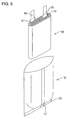
- a method of receiving an electricity-generating element into a bag-shaped battery case has been put to practical use. For example, it has been practiced to prepare a thin secondary battery from a metal-laminated resin film having an airtight structure as a bag-shaped battery case. In this arrangement, a battery having a reduced weight and a high energy density per unit weight free from electrolyte leak and contamination of water from the exterior of the battery can be provided.
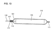
- Such a thin secondary battery has heretofore been prepared, for example, as shown in Figs. 11 to 14.
- Lead members 101 and 103 are ultrasonically welded to positive and negative electrodes, respectively.
- the positive electrode and the negative electrode are then wound with a separator provided interposed therebetween into an ellipsoidal shape to prepare an electricity-generating element 105.
- the electricity-generating element 105 is inserted into the battery case 107 from its opening with the lead members 101 and 103 drawn from the electricity-generating element 105 being extending from the opening of the battery case 107.
- An electrolytic solution is then injected into the interior of the battery case 107.
- the edges of the opening of the battery case 107 are heat-sealed to each other to form a sealed portion 113 and hence seal the opening of the battery case 107.
- a thin secondary battery 115 was obtained as shown in Figs. 12 and 13.
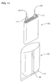
- the lead members 101 and 103 extend from the opening of the battery case 107 with a thermoplastic resin coat layer 117 interposed therebetween.
- the lead members 101 and 103 which are outside the sealed portion 113 of the battery case 107 as they are form external terminals 119 and 120, respectively.
- the position of the electricity-generating element 107 relative to the battery case 107 deviates leftward from the predetermined value.
- the position of the electricity-generating element 107 relative to the battery case 107 deviates rightward from the predetermined value. This causes the position of the external terminals 119 and 120 relative to the battery case 107 to vary.
- the battery case 107 is made of a flexible laminated film, the position of the electricity-generating element 105 relative to the battery case 107 can easily vary, increasing the variation of the position of the external terminals 119 and 120.
- the position of attachment can vary.
- the lead members 101 and 103 as they are, form the external terminals 119 and 120, respectively, the variation of the attached position of the lead members 101 and 103 directly cause the position of the external terminals 119 and 120 to vary, respectively.
- the position of the external terminals 119 and 120 can vary, increasing the production of defectives during the production process.
- the opening of the battery case is sealed with both the positive electrode lead member and the negative electrode lead member leading to the exterior thereof, and the position of the battery case and the electricity-generating element relative to each other is fixed.
- the position of the positive electrode lead member and the negative electrode lead member relative to the battery case can be fixed.
- the position of the positive electrode lead member and the negative electrode lead member relative to the battery case can vary.
- the battery case is in the form of bag made of flexible metal-laminated resin film, the resulting variation in the position of the external terminals is great.
- the positive electrode lead member and/or the negative electrode lead member is/are worked with a predetermined position of the battery case as reference. In this manner, the position of the positive electrode lead member and the negative electrode lead member relative to the battery can be corrected to reduce its variation.
- the positive electrode lead member and/or the negative electrode lead member can be worked, making it possible to lessen the variation in position developed due to various causes prior to this working step.
- a very simple method can be used to lessen the variation of the position of the external terminals formed by the positive electrode lead member and the negative electrode lead member, making it possible to provide a battery having external terminals in stable positions.
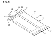
- the battery prepared by the preparation process of the present invention comprises, for example, an electricity-generating element 50 received in a bag-shaped battery case 51, said electricity-generating element 50 being formed by winding a belt-like positive electrode 10 and a belt-like negative electrode 20 with a separator 30 into a flat shape.
- the positive electrode 10 comprises an aluminum foil 12 as a current collector having a positive active material 14 (shown by the shade in Fig. 1) such as lithium cobalt oxide (LiCoO 2 ) coated on the both sides thereof as shown in Fig. 1.
- the negative electrode 20 comprises a copper foil 22 as a current collector having a negative active material 24 (shown by the shade in Fig. 2) such as graphite coated on the both sides thereof as shown in Fig. 2.
- the aluminum foil 12 constituting the positive electrode 10 is free of positive electrode compound 14 at an end thereof to which a positive electrode lead member 16 made of aluminum is ultrasonically welded.
- the positive electrode lead member 16 extends upward from the electricity-generating element 50.
- the copper foil 22 constituting the negative electrode 20 is free of negative electrode compound 24 at an end thereof to which a negative electrode lead member 26 made of nickel is ultrasonically welded.
- the negative electrode lead member 26 extends upward from the electricity-generating element 50.
- thermoplastic resin coat layer 91 as shown in Figs. 1 and 2 to assure that the thermoplastic resin coat layer 91 can be heat-fused to make airtight sealing.
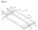
- the positive electrode lead member 16 and the negative electrode lead member 26 to be used herein have a width D1 greater than the width D2 of external terminals 81 and 83 of a completed battery shown in Fig. 9.
- the positive electrode 10 and the negative electrode 20 are laminated on each other with a separator 30 provided interposed therebetween as shown in Fig. 3. As shown in Fig. 4, the laminate is then wound in such an arrangement that it is folded at a predetermined width from the end of the laminate to form a flat electricity-generating element 50. In the wound form, the positive electrode compound 14 and the negative electrode compound 24 are opposed to each other with the separator 30 provided interposed therebetween.
- a non-aqueous electrolyte e.g., 1 : 1 : 1 mixture of ethylene carbonate, diethyl carbonate and dimethyl carbonate having hexafluorinated lithium phosphate incorporated therein
- the electricity-generating element 50 is then received into the battery case 51 through the opening thereof.
- An electrolytic solution is then injected into the battery case.
- the opening of the battery case is closed, and the both edges of the opening is then pressure-bonded to each other under heating to seal the opening of the battery case 51.
- the both edges of the opening of the battery case 51 are bonded to each other with the positive electrode lead member 16 and the negative electrode lead member 26 interposed therebetween.
- the positive electrode lead member 16 is punched in such an arrangement that the distance between the end 71 of the sealed portion 61 and the edges 73 and 74 of the positive electrode lead member 16 are predetermined values D3 and D4, respectively.
- the negative electrode lead member 26 is punched in such an arrangement that the distance between the end 71 of the sealed portion 61 and the edges 75 and 76 of the negative electrode lead member 26 are predetermined values D5 and D6, respectively.
- the working is conducted in such an arrangement that the position of the external terminals 81 and 83 from the end 71 of the sealed portion 61 are fixed, making it possible to correct the variation of the position of the external terminals 81 and 83 developed during preparation.
- the electrolytic solution to be incorporated in the polymer and the electrolytic solution to be contained in the pores of the polymer may differ from each other.
- the electricity-generating element 50 may be in any other forms such as those having a circular or non-circular coil section, or laminate of flat electrodes with a separator provided interposed therebetween or folded material obtained by folding sheet-like electrodes with a separator provided interposed therebetween.
- the present invention is not limited thereto and the battery case 51 may be obtained by vacuum-forming, air pressure-forming or pressure-forming a film or sheet.
Landscapes
- Chemical & Material Sciences (AREA)
- Chemical Kinetics & Catalysis (AREA)
- Electrochemistry (AREA)
- General Chemical & Material Sciences (AREA)
- Engineering & Computer Science (AREA)
- Manufacturing & Machinery (AREA)
- Inorganic Chemistry (AREA)
- Secondary Cells (AREA)
- Sealing Battery Cases Or Jackets (AREA)
- Connection Of Batteries Or Terminals (AREA)
Applications Claiming Priority (2)
| Application Number | Priority Date | Filing Date | Title |
|---|---|---|---|
| JP2000226740A JP2002042778A (ja) | 2000-07-27 | 2000-07-27 | 電池の製造方法及び電池 |
| JP2000226740 | 2000-07-27 |
Publications (1)
| Publication Number | Publication Date |
|---|---|
| EP1176648A2 true EP1176648A2 (en) | 2002-01-30 |
Family
ID=18720305
Family Applications (1)
| Application Number | Title | Priority Date | Filing Date |
|---|---|---|---|
| EP01118350A Withdrawn EP1176648A2 (en) | 2000-07-27 | 2001-07-27 | Process for the preparation of battery |
Country Status (3)
| Country | Link |
|---|---|
| US (1) | US20020010998A1 (enExample) |
| EP (1) | EP1176648A2 (enExample) |
| JP (1) | JP2002042778A (enExample) |
Families Citing this family (14)
| Publication number | Priority date | Publication date | Assignee | Title |
|---|---|---|---|---|
| US7482097B2 (en) * | 2002-04-03 | 2009-01-27 | Valence Technology, Inc. | Alkali-transition metal phosphates having a +3 valence non-transition element and related electrode active materials |
| US20030190527A1 (en) * | 2002-04-03 | 2003-10-09 | James Pugh | Batteries comprising alkali-transition metal phosphates and preferred electrolytes |
| US7422823B2 (en) * | 2002-04-03 | 2008-09-09 | Valence Technology, Inc. | Alkali-iron-cobalt phosphates and related electrode active materials |
| US7179562B2 (en) * | 2003-02-14 | 2007-02-20 | Quallion Llc | Battery electrode assembly and fabrication method therefor |
| JP4961673B2 (ja) * | 2005-03-08 | 2012-06-27 | 住友電気工業株式会社 | 非水電解質電池用タブリードの製造方法 |
| JP4745122B2 (ja) * | 2006-05-18 | 2011-08-10 | 日立ビークルエナジー株式会社 | 二次電池、組電池および電池モジュール |
| KR101101046B1 (ko) * | 2009-12-01 | 2011-12-29 | 삼성에스디아이 주식회사 | 전극 조립체 및 그를 구비하는 이차 전지 |
| JP2013012458A (ja) * | 2011-05-27 | 2013-01-17 | Sony Corp | バッテリユニット、バッテリモジュール、蓄電システム、電子機器、電力システムおよび電動車両 |
| JP5743791B2 (ja) * | 2011-08-02 | 2015-07-01 | 三洋電機株式会社 | 電源装置及び電源装置を備える車両 |
| KR101867614B1 (ko) * | 2011-12-08 | 2018-06-15 | 삼성에스디아이 주식회사 | 전극 조립체와 이를 구비한 이차전지 |
| US20150072220A1 (en) * | 2012-03-30 | 2015-03-12 | Nec Corporation | Lithium Secondary Battery and Method for Manufacturing Same |
| US20160211547A1 (en) * | 2015-01-15 | 2016-07-21 | Google Inc. | Hybrid Rechargeable Battery |
| JP7135001B2 (ja) * | 2017-12-20 | 2022-09-12 | 株式会社エンビジョンAescジャパン | 電池 |
| JP7232803B2 (ja) * | 2020-10-29 | 2023-03-03 | プライムプラネットエナジー&ソリューションズ株式会社 | 蓄電セルおよびその製造方法 |
Family Cites Families (7)
| Publication number | Priority date | Publication date | Assignee | Title |
|---|---|---|---|---|
| JPH0197371A (ja) * | 1987-10-08 | 1989-04-14 | Seiko Electronic Components Ltd | リード端子付平板型リチウム電池の製造方法 |
| JPH07320715A (ja) * | 1994-05-23 | 1995-12-08 | Matsushita Electric Ind Co Ltd | 偏平形電池およびその端子板の製造法 |
| JPH09274896A (ja) * | 1996-04-04 | 1997-10-21 | Sumitomo Electric Ind Ltd | 非水電解質電池 |
| JP4057672B2 (ja) * | 1997-03-21 | 2008-03-05 | 株式会社東芝 | タブ付き部品製造装置 |
| JP4237286B2 (ja) * | 1998-02-18 | 2009-03-11 | パナソニック株式会社 | ラミネートシートを外装ケースとする電池 |
| JP4491843B2 (ja) * | 1998-02-24 | 2010-06-30 | ソニー株式会社 | リチウムイオン二次電池、およびリチウムイオン二次電池の容器の封じ方法 |
| JP3787437B2 (ja) * | 1998-07-31 | 2006-06-21 | 日本特殊陶業株式会社 | 扁平型電池及びその製造方法 |
-
2000
- 2000-07-27 JP JP2000226740A patent/JP2002042778A/ja active Pending
-
2001
- 2001-07-26 US US09/912,519 patent/US20020010998A1/en not_active Abandoned
- 2001-07-27 EP EP01118350A patent/EP1176648A2/en not_active Withdrawn
Also Published As
| Publication number | Publication date |
|---|---|
| JP2002042778A (ja) | 2002-02-08 |
| US20020010998A1 (en) | 2002-01-31 |
Similar Documents
| Publication | Publication Date | Title |
|---|---|---|
| US10461369B2 (en) | Battery and battery pack | |
| JP6250921B2 (ja) | 電池 | |
| EP2461391B1 (en) | Battery | |
| JP4862211B2 (ja) | 密閉型二次電池 | |
| EP1176648A2 (en) | Process for the preparation of battery | |
| JP2007179803A (ja) | 電池容器用封口板および非水電解液電池 | |
| JP4432146B2 (ja) | 非水電解質二次電池 | |
| JP2000277066A5 (enExample) | ||
| JP4918997B2 (ja) | 非水電解質二次電池 | |
| JP2012064459A (ja) | 非水電解質電池 | |
| JP4751995B2 (ja) | 電池 | |
| JP2003346768A (ja) | 非水電解質二次電池 | |
| JP2008027849A (ja) | シール部材 | |
| JP2000090897A (ja) | 電池および電池パック | |
| US7704636B2 (en) | Cell having film outer casing | |
| JP2000285902A5 (enExample) | ||
| JP2025528940A (ja) | エネルギー貯蔵セル、及びこのようなエネルギー貯蔵セルの製造方法 | |
| JP2000357536A (ja) | 非水電解質電池 | |
| JP2003346879A (ja) | 電 池 | |
| JP2004014189A (ja) | 非水電解質二次電池 | |
| JPH07220705A (ja) | 積層型リチウム二次電池の安全装置 | |
| US20250046925A1 (en) | Unit cell | |
| JP3541770B2 (ja) | 非水電解質二次電池 | |
| JP2000277065A (ja) | 非水電解質二次電池 | |
| KR101595613B1 (ko) | 리튬 이차전지용 음극 및 이를 포함하는 리튬이온 이차 전지 |
Legal Events
| Date | Code | Title | Description |
|---|---|---|---|
| PUAI | Public reference made under article 153(3) epc to a published international application that has entered the european phase |
Free format text: ORIGINAL CODE: 0009012 |
|
| AK | Designated contracting states |
Kind code of ref document: A2 Designated state(s): AT BE CH CY DE DK ES FI FR GB GR IE IT LI LU MC NL PT SE TR |
|
| AX | Request for extension of the european patent |
Free format text: AL;LT;LV;MK;RO;SI |
|
| STAA | Information on the status of an ep patent application or granted ep patent |
Free format text: STATUS: THE APPLICATION IS DEEMED TO BE WITHDRAWN |
|
| 18D | Application deemed to be withdrawn |
Effective date: 20040203 |