EP1176325A2 - Palier magnétique - Google Patents
Palier magnétique Download PDFInfo
- Publication number
- EP1176325A2 EP1176325A2 EP01118169A EP01118169A EP1176325A2 EP 1176325 A2 EP1176325 A2 EP 1176325A2 EP 01118169 A EP01118169 A EP 01118169A EP 01118169 A EP01118169 A EP 01118169A EP 1176325 A2 EP1176325 A2 EP 1176325A2
- Authority
- EP
- European Patent Office
- Prior art keywords
- magnetic flux
- power amplifier
- magnetic
- sensor
- bearing apparatus
- Prior art date
- Legal status (The legal status is an assumption and is not a legal conclusion. Google has not performed a legal analysis and makes no representation as to the accuracy of the status listed.)
- Withdrawn
Links
Images


Classifications
-
- F—MECHANICAL ENGINEERING; LIGHTING; HEATING; WEAPONS; BLASTING
- F16—ENGINEERING ELEMENTS AND UNITS; GENERAL MEASURES FOR PRODUCING AND MAINTAINING EFFECTIVE FUNCTIONING OF MACHINES OR INSTALLATIONS; THERMAL INSULATION IN GENERAL
- F16C—SHAFTS; FLEXIBLE SHAFTS; ELEMENTS OR CRANKSHAFT MECHANISMS; ROTARY BODIES OTHER THAN GEARING ELEMENTS; BEARINGS
- F16C32/00—Bearings not otherwise provided for
- F16C32/04—Bearings not otherwise provided for using magnetic or electric supporting means
- F16C32/0406—Magnetic bearings
- F16C32/044—Active magnetic bearings
- F16C32/0444—Details of devices to control the actuation of the electromagnets
- F16C32/0457—Details of the power supply to the electromagnets
-
- F—MECHANICAL ENGINEERING; LIGHTING; HEATING; WEAPONS; BLASTING
- F16—ENGINEERING ELEMENTS AND UNITS; GENERAL MEASURES FOR PRODUCING AND MAINTAINING EFFECTIVE FUNCTIONING OF MACHINES OR INSTALLATIONS; THERMAL INSULATION IN GENERAL
- F16C—SHAFTS; FLEXIBLE SHAFTS; ELEMENTS OR CRANKSHAFT MECHANISMS; ROTARY BODIES OTHER THAN GEARING ELEMENTS; BEARINGS
- F16C2360/00—Engines or pumps
- F16C2360/44—Centrifugal pumps
- F16C2360/45—Turbo-molecular pumps
Definitions
- the present invention relates to a magnetic bearing apparatus for supporting an object by a magnetic force without contact and, in particular, to a magnetic bearing apparatus suitable for use in a high-speed rotation apparatus (e.g., a turbo-molecular pump and a centrifugal compressor), a rotary apparatus for semiconductor device manufacturing apparatuses which, though rotating at low speed, advantageously supports an object without contact, a gas circulating fan or the like.
- a high-speed rotation apparatus e.g., a turbo-molecular pump and a centrifugal compressor
- a rotary apparatus for semiconductor device manufacturing apparatuses which, though rotating at low speed, advantageously supports an object without contact
- a gas circulating fan or the like e.g., a gas circulating fan or the like.
- a control type magnetic bearing apparatus comprises a displacement sensor for detecting a relative displacement with respect to a supported object. On the basis of the relative displacement, a control current is calculated using a predetermined control rule and the result of calculation is fed to a power amplifier which supplies a current to a coil of a supporting electromagnet and drives the electromagnet. Since a load of this power amplifier is an electromagnet coil, its load characteristics can be assumed to be delay characteristics. Due to the delay characteristics, the higher the frequency, the greater the delay generated in its relationship with the control current with respect to a power amplifier input signal.
- an electromagnet coil current is detected and fed back to the input of the power amplifier (which is referred to as a "current feedback type power amplifier”).
- a coil voltage applied to the electromagnet coil is detected and fed back to the input of the power amplifier (which is referred to as a "voltage feedback type power amplifier”).
- a magnetic flux generated in a gap between the electromagnet and the supported object is detected and fed back to the input of the power amplifier (which is referred to as a “magnetic flux feedback type power amplifier”).
- Fig. 1 is a diagram showing a structural example of a magnetic bearing apparatus adopting the current feedback type power amplifier.
- Fig. 1 shows a one-axis portion of the bearing apparatus.
- reference numeral 1 indicates a supported object, which is provided with a sensor target 2 and an electromagnet target 3.
- On a supporting member (not shown), there are provided a displacement sensor 10 and an electromagnet 4 in correspondence with the sensor target 2 and the electromagnet target 3, respectively.
- the displacement sensor 10 is connected to a displacement sensor amplifier 9, which outputs a displacement detection signal Sg indicating a length g of the gap between the displacement sensor 10 and the sensor target 2.
- a compensator 8 is provided with a control rule for positioning the supported object at the target position without any contact, and the output of the compensator 8 is a control command signal S1.
- the control command signal S1 is input to a power amplifier 7, and a control current i following-up to the control command signal S1 is supplied to an electromagnet coil 6 of the electromagnet 4.
- the coil load of the electromagnet 4 is a delay load, so that the electromagnet 4 cannot follow the input signal.
- the control current i of the electromagnet coil 6 is detected by a current sensor 11 to perform local feedback. That is, a control current detection signal Si detected by the current sensor 11 is fed back (negative feedback) to the input of the power amplifier 7 through a regulator 12.
- Fig. 2 is a diagram showing a structural example of a magnetic bearing apparatus using the voltage feedback type power amplifier.
- This magnetic bearing apparatus is provided with a voltage sensor 13 for detecting a coil voltage applied to the electromagnet coil 6 of the electromagnet 4, and a detection voltage signal Sv detected by the voltage sensor 13 is fed back to the input of the power amplifier 7 through the regulator 12 (negative feedback).
- this arrangement helps to improve the delay load characteristics.
- Fig. 3 is a diagram showing a structural example of a magnetic bearing using the magnetic-flux feedback type power amplifier.
- a magnetic flux sensor 14 consisting of a Hall element or the like for detecting a magnetic flux ⁇ is provided on the surface of an electromagnetic yoke 5 of the electromagnet 4 opposed to the electromagnet target 3.
- a detected magnetic flux signal S ⁇ of the magnetic flux sensor 14 is negatively fed back to the input of the power amplifier 7 through the regulator 12.
- This magnetic flux feedback type power amplifier system has been proposed to improve a phase delay in the magnetic flux (equivalent to a control force), taking into consideration, in addition to the coil load of the electromagnet coil 6, transfer characteristics of the control current i supplied to the electromagnet coil 6 and of the generated magnetic flux ⁇ , which depend on the characteristics of magnetic materials forming the electromagnetic yoke 5 of the electromagnet 4 and the electromagnet target 3.
- a phase delay in the magnetic flux (equivalent to a control force)
- transfer characteristics of the control current i supplied to the electromagnet coil 6 and of the generated magnetic flux ⁇ which depend on the characteristics of magnetic materials forming the electromagnetic yoke 5 of the electromagnet 4 and the electromagnet target 3.
- the magnetic flux feedback type power amplifier constructed as shown in Fig. 3 is preferably used.
- a magnetic flux sensor which must be mounted not within the controller but in the vicinity of the electromagnet of the magnetic bearing apparatus connected with a long cable, resulting in a disadvantage of an increase in the number of signal lines in the cable.
- a magnetic bearing apparatus is used in a vacuum atmosphere, it is necessary to take the signal lines out to the outside through a hermetically sealed connector. It is desirable that as small number of connector pins as possible are used. However, this requirement is contradictory to an increase in the number of signal lines in the cable.
- using a thin Hall element in the magnetic flux sensor is disadvantageous in that such a sensor is easily broken and that there is no space for mounting a secondary coil.
- the present invention has been made in view of the above, and an object of the present invention is to provide a magnetic bearing apparatus having no necessity of providing a magnetic flux sensor in the vicinity of a supporting electromagnet and no necessity of increasing the number of signal lines in a cable and capable of achieving an advantage similar to a magnetic flux feedback type power amplifier in a controller.
- the present invention provides a control type magnetic bearing apparatus having a supporting electromagnet capable of generating a magnetic force generated by supplying a control current to a coil of a supporting electromagnet from a power amplifier to support a supported member by the magnetic force.
- the magnetic bearing apparatus comprises a current sensor for detecting a control current output from the power amplifier and a displacement sensor for detecting a displacement of the supported member.
- Magnetic flux or magnetic flux density estimating means is provided to receive as input signals at least a control current detection signal of the current sensor and a displacement detection signal of the displacement sensor.
- the estimating means estimates a magnetic flux or magnetic flux density generated between a surface of the electromagnet and an electromagnetic target on the supported member. An estimated value of the magnetic flux or magnetic flux estimating means is fed back to the power amplifier that supplies a control current to a coil of the supporting electromagnet.
- the magnetic flux or magnetic flux density estimating means is provided, and the magnetic flux or magnetic flux density generated between a surface of the electromagnetic and the electromagnetic target on the supported member is estimated on the basis of the control current detection signal of the current sensor and the displacement detection signal of the displacement sensor.
- the estimated value is fed back to the power amplifier. Consequently, an improvement can be achieved, as in the magnetic flux feedback power amplifier, taking into consideration, in addition to a coil load of an electromagnet coil. transfer characteristics of a current flowing through the electromagnetic coil and generated magnetic fluxes due to characteristics of magnetic materials forming the electromagnetic yoke of the electromagnet and the electromagnetic target. Further, since the magnetic flux density estimating means is disposed within the controller, the number of signal lines within the cable is not increased.
- a control current detection signal of the current sensor is fed back to the power amplifier.
- a voltage sensor is provided for detecting a coil voltage of the supporting electromagnet, a coil voltage detection signal of the voltage sensor being fed back to the power amplifier.
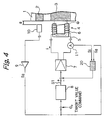
- Fig. 4 is a diagram showing a structural example of a magnetic bearing apparatus in accordance with the present invention.
- a displacement sensor 10 and an electromagnet 4 are disposed facing to a sensor target 2 and an electromagnetic target 3 of a supported member 1, respectively.
- the displacement sensor 10 is connected to a displacement sensor amplifier 9 and outputs a displacement detection signal Sg indicative of a gap length g between the displacement sensor 10 and the sensor target 2.
- a target position of the supported member 1 is given based on a displacement detection signal Sg and a target command signal E o .
- a control command signal S1 is outputted to a power amplifier 7 from a compensator 8.
- An estimator 20 operates to estimate a magnetic flux or a magnetic flux density which is generated between a surface of an electromagnetic yoke 5 on the supporting member and the electromagnetic target 3 on the supported member 1.
- a control current detection signal Si detected by a current sensor 11 and the displacement detection signal Sg detected by the displacement sensor 10.
- the estimator 20 receives the control current detection signal Si and the displacement detection signal Sg as input signals and estimates the magnetic flux ⁇ or the magnetic flux density B generated between the surface of the electromagnetic yoke 5 and the electromagnetic target 3, the estimated value being fed back to the input of the power amplifier 7.
- the adjustment of a gain for example, is also effected in the estimator 20.
- Fig. 5 is a diagram for explaining a magnetic circuit of the electromagnet.
- the figure shows an example of a magnetic circuit that can ignore a leak magnetic flux.
- a dotted line L denotes an average magnetic path.
- the magnetic flux ⁇ at the gap g between the end surface of the electromagnetic yoke 5 and the surface of the electromagnetic target 3 is equal to a product of the magnetic flux density B and the sectional area A.
- the equation (1) represents a relationship between the magnetic flux density and other parameters.
- the specific magnetic permeability ⁇ S1 of the electromagnetic yoke and the magnetic permeability ⁇ S2 of the electromagnetic target are variables of the intensity H of the magnetic flux density or magnetic field and the frequency thereof. Conventionally. there are a variety of applications where it is sufficient that those values are considered as constants. If these values cannot be ignored, the magnetic feedback type power amplifier structured as shown in Fig. 3 has been adopted.
- Fig. 6 is a graph showing general transfer characteristics of a coil current of the electromagnet and a generated magnetic flux or magnetic flux density. In this figure, a gain is omitted and a phase characteristic is exhibited.
- a curve (1) exhibits a case in which a laminate structure of a silicon steel plate is used for the electromagnetic yoke and the electromagnetic target;
- a curve (2) a case in which a drive voltage is high and a laminate structure of a silicon steel plate is used (If the drive voltage is high because of an increase in iron loss, the phase characteristic in the laminate structure of the silicon steel plate is deteriorated as compared with curve (1)); and a curve (3) a case in which a solid magnetic material is used for the electromagnetic yoke and the electromagnetic target.
- the transfer characteristic of the coil current and the generated magnetic flux or magnetic flux density is a delay characteristic.
- the delay characteristic is different depending on magnetic materials and constructions that constitute the electromagnetic yoke and the electromagnetic target.
- the transfer characteristic of the magnetic bearing apparatus for the special purpose tends to show a deteriorated phase characteristic indicated by an arrow C in Fig. 6.
- a phase delay transfer function of the coil current of the electromagnetic coil current and the magnetic flux ⁇ and the magnetic flux density B can be represented by a transfer function equations of low pass filters shown in Figs. 7(a) and 7(b).
- Such a transfer function can be obtained by curve-fitting actual data and making a calculation of an equation, or can be simulated by a simple analog circuit.
- Fig. 7(a) shows the structure of a low pass filter using passive elements
- Fig. 7(b) shows the structure of a low pass filter using an operational amplifier.
- Fig. 8 is a diagram showing a structural example of the estimator 20.
- a signal corresponding to the magnetic flux can be obtained within the controller without detecting the magnetic flux ⁇ nor increasing the number of signal lines of the cable and is fed back to the power amplifier 7.
- Input signals necessary for the estimator 20 are the displacement detection signal Sg of the displacement sensor 10 and the control current detection signal Si of the current sensor 11, which signals are generated in a conventional magnetic bearing apparatus.
- Fig. 9 is a diagram showing another structural example of a magnetic bearing apparatus in accordance with the present invention.
- the magnetic bearing apparatus shown in Fig. 9 is different from one shown in Fig. 4 in that a adjuster 12 is disposed, and the control current detection signal Si detected by the current sensor 11 is fed back to the power amplifier 7 through the adjuster 12.
- the magnetic bearing apparatus shown in Fig. 9 uses the estimator 20 that estimates the magnetic flux or the magnetic flux density, together with a conventional current feedback type power amplifier as shown in Fig. 1.
- Fig. 10 is a diagram showing a further structural example of a magnetic bearing apparatus in accordance with the present invention.
- the magnetic bearing apparatus shown in Fig. 10 is different from the magnetic bearing apparatus shown in Fig. 4 in that there are provided an adjuster 12 and a voltage sensor 13 that detects a coil voltage applied to the electromagnetic coil 6.
- the detected voltage signals Sv detected by the voltage sensor 13 is fed back to the power amplifier 7 through the adjuster 12.
- the magnetic bearing apparatus shown in Fig. 10 uses the estimator 20 that estimates the magnetic flux or the magnetic flux density, together with a conventional voltage feedback type power amplifier as shown in Fig. 2.
- Fig. 11 is a diagram showing the structure of an apparatus that adopts a general magnetic bearing apparatus.
- a magnetic bearing controller 100 is connected by a relatively long (for example, about 20 m) cable 102 to a rotary machine 101 in which a magnetic bearing apparatus is incorporated for supporting an object without contact.
- the displacement detection signal Sg of the displacement sensor 10, the control current detection signal Si detected by the current sensor 11 and the detection voltage signal Sv detected by the voltage sensor 13 are transmitted to the magnetic bearing controller 100 from the magnetic bearing apparatus of the rotary machine 101 through the cable 102.
- the control current i is supplied to rotary machine 101 from the power amplifier 7 of the magnetic bearing controller 100 through the cable 102.
- the present invention is capable of bringing about various advantages.
- the magnetic flux density estimating means is provided for estimating a magnetic flux or a magnetic flux density generated between a surface of the electromagnet on the supporting side and the electromagnetic target on the supported member.
- the estimated value is fed back to the power amplifier. Consequently, an improvement can be achieved, as in the magnetic flux feedback power amplifier, taking into consideration, in addition to a coil load of an electromagnet coil, transfer characteristics of a current flowing through the electromagnetic coil and generated magnetic fluxes due to characteristics of magnetic materials forming the electromagnetic yoke of the electromagnet and the electromagnetic target.
- the magnetic flux density estimating means is disposed within the controller, the number of signal lines within the cable is not increased.
- the present invention is advantageous in that an industrial reliability can be improved by adding, to a magnetic bearing apparatus according to the present invention, a conventional current feedback type power amplifier system in which a coil current detection signal of the current sensor is fed back to the power amplifier.
- An industrial reliability can also be improved by adding, to a magnetic bearing apparatus according to the present invention, a conventional voltage feedback type power amplifier system in which a coil voltage detection signal of the voltage sensor is fed back to the power amplifier.
Landscapes
- Engineering & Computer Science (AREA)
- General Engineering & Computer Science (AREA)
- Physics & Mathematics (AREA)
- Electromagnetism (AREA)
- Mechanical Engineering (AREA)
- Magnetic Bearings And Hydrostatic Bearings (AREA)
Applications Claiming Priority (2)
| Application Number | Priority Date | Filing Date | Title |
|---|---|---|---|
| JP2000227608A JP2002039178A (ja) | 2000-07-27 | 2000-07-27 | 磁気軸受装置 |
| JP2000227608 | 2000-07-27 |
Publications (2)
| Publication Number | Publication Date |
|---|---|
| EP1176325A2 true EP1176325A2 (fr) | 2002-01-30 |
| EP1176325A3 EP1176325A3 (fr) | 2004-05-12 |
Family
ID=18721027
Family Applications (1)
| Application Number | Title | Priority Date | Filing Date |
|---|---|---|---|
| EP01118169A Withdrawn EP1176325A3 (fr) | 2000-07-27 | 2001-07-26 | Palier magnétique |
Country Status (4)
| Country | Link |
|---|---|
| US (1) | US20020011754A1 (fr) |
| EP (1) | EP1176325A3 (fr) |
| JP (1) | JP2002039178A (fr) |
| KR (1) | KR20020010100A (fr) |
Families Citing this family (6)
| Publication number | Priority date | Publication date | Assignee | Title |
|---|---|---|---|---|
| FR2817088B1 (fr) * | 2000-11-17 | 2003-02-21 | Mecanique Magnetique Sa | Machine tournante a butee axiale magnetique integrant une generatrice de courant |
| US7107163B1 (en) * | 2003-05-06 | 2006-09-12 | Lockheed Martin Corporation | Magnetic levitation force control |
| JP2005140190A (ja) * | 2003-11-05 | 2005-06-02 | Koyo Seiko Co Ltd | 電力増幅装置および磁気軸受 |
| JP5236571B2 (ja) * | 2009-05-13 | 2013-07-17 | 国立大学法人埼玉大学 | 磁気浮上装置 |
| JP5279890B2 (ja) * | 2011-12-29 | 2013-09-04 | 株式会社大阪真空機器製作所 | ラジアル方向制御器及び、それが適用された磁気軸受装置 |
| KR102026009B1 (ko) * | 2018-01-05 | 2019-09-26 | 엘지전자 주식회사 | 자기 베어링 제어장치 및 그 제어방법 |
Citations (3)
| Publication number | Priority date | Publication date | Assignee | Title |
|---|---|---|---|---|
| US5003211A (en) * | 1989-09-11 | 1991-03-26 | The United States Of America As Represented By The Administrator Of The National Aeronautics And Space Administration | Permanent magnet flux-biased magnetic actuator with flux feedback |
| US5471106A (en) * | 1993-03-08 | 1995-11-28 | Noise Cancellation Technologies, Inc. | Methods and apparatus for closed-loop control of magnetic bearings |
| JPH0925934A (ja) * | 1995-07-12 | 1997-01-28 | Ishikawajima Harima Heavy Ind Co Ltd | 磁気軸受制御装置 |
Family Cites Families (4)
| Publication number | Priority date | Publication date | Assignee | Title |
|---|---|---|---|---|
| US5036236A (en) * | 1990-05-07 | 1991-07-30 | Hughes Aircraft Company | Air gap matching proximity sensor for magnetic bearings |
| NL9001909A (nl) * | 1990-08-30 | 1992-03-16 | Philips Nv | Elektromagnetische ondersteuning met enkelzijdige regelstromen. |
| JP4005654B2 (ja) * | 1996-12-26 | 2007-11-07 | Ntn株式会社 | 磁気浮上型遠心式ポンプ装置 |
| US6091215A (en) * | 1998-06-02 | 2000-07-18 | Switched Reluctance Drives Limited | Trajectory controller |
-
2000
- 2000-07-27 JP JP2000227608A patent/JP2002039178A/ja active Pending
-
2001
- 2001-07-26 EP EP01118169A patent/EP1176325A3/fr not_active Withdrawn
- 2001-07-26 US US09/912,338 patent/US20020011754A1/en not_active Abandoned
- 2001-07-27 KR KR1020010045406A patent/KR20020010100A/ko not_active Application Discontinuation
Patent Citations (3)
| Publication number | Priority date | Publication date | Assignee | Title |
|---|---|---|---|---|
| US5003211A (en) * | 1989-09-11 | 1991-03-26 | The United States Of America As Represented By The Administrator Of The National Aeronautics And Space Administration | Permanent magnet flux-biased magnetic actuator with flux feedback |
| US5471106A (en) * | 1993-03-08 | 1995-11-28 | Noise Cancellation Technologies, Inc. | Methods and apparatus for closed-loop control of magnetic bearings |
| JPH0925934A (ja) * | 1995-07-12 | 1997-01-28 | Ishikawajima Harima Heavy Ind Co Ltd | 磁気軸受制御装置 |
Non-Patent Citations (1)
| Title |
|---|
| PATENT ABSTRACTS OF JAPAN vol. 1997, no. 05, 30 May 1997 (1997-05-30) & JP 09 025934 A (ISHIKAWAJIMA HARIMA HEAVY IND CO LTD), 28 January 1997 (1997-01-28) * |
Also Published As
| Publication number | Publication date |
|---|---|
| JP2002039178A (ja) | 2002-02-06 |
| KR20020010100A (ko) | 2002-02-02 |
| US20020011754A1 (en) | 2002-01-31 |
| EP1176325A3 (fr) | 2004-05-12 |
Similar Documents
| Publication | Publication Date | Title |
|---|---|---|
| US10619669B2 (en) | Magnetic bearing control device and vacuum pump | |
| JP3919436B2 (ja) | 磁気浮上回転機械 | |
| KR101325542B1 (ko) | 자력 센서 | |
| JP6351400B2 (ja) | 改良された能動型磁気軸受制御システム | |
| JPH07111215B2 (ja) | 除振装置 | |
| US7626348B2 (en) | Linear motor door actuator | |
| EP1079122B1 (fr) | Palier magnétique | |
| EP1176325A2 (fr) | Palier magnétique | |
| Matsuda et al. | Self-sensing active suppression of vibration of flexible steel sheet | |
| JP3649595B2 (ja) | 磁気浮上制御装置 | |
| EP0949744B1 (fr) | Actionneur électromagnétique avec fonction de détection de la position de l'élément entraíné | |
| CA2548861C (fr) | Verin de porte a moteur lineaire | |
| JP2000258449A (ja) | 磁気式加速度センサ及び加速度検知装置 | |
| JPS6411845B2 (fr) | ||
| US6848308B2 (en) | Circuit arrangement for evaluating an acceleration sensor using the Ferraris principle | |
| US20070080594A1 (en) | Power amplification device and magnetic bearing | |
| JP2012501444A (ja) | 受動渦電流センサ用高温エレクトロニクス | |
| JPH0674297A (ja) | 電磁アクチュエータ | |
| Hofer et al. | Analysis of a Current Biased Eight-Pole Radial Active Magnetic Bearing Regarding Self-Sensing | |
| JPH1151968A (ja) | 振動センサ | |
| JP3292505B2 (ja) | アクティブ振動絶縁装置 | |
| JPH05244790A (ja) | リニアモータ制御回路 | |
| JP3311394B2 (ja) | 電磁石制御装置 | |
| JPH07139546A (ja) | 磁気軸受装置 | |
| JP3258149B2 (ja) | 磁気軸受装置 |
Legal Events
| Date | Code | Title | Description |
|---|---|---|---|
| PUAI | Public reference made under article 153(3) epc to a published international application that has entered the european phase |
Free format text: ORIGINAL CODE: 0009012 |
|
| AK | Designated contracting states |
Kind code of ref document: A2 Designated state(s): AT BE CH CY DE DK ES FI FR GB GR IE IT LI LU MC NL PT SE TR |
|
| AX | Request for extension of the european patent |
Free format text: AL;LT;LV;MK;RO;SI |
|
| PUAL | Search report despatched |
Free format text: ORIGINAL CODE: 0009013 |
|
| AK | Designated contracting states |
Kind code of ref document: A3 Designated state(s): AT BE CH CY DE DK ES FI FR GB GR IE IT LI LU MC NL PT SE TR |
|
| AX | Request for extension of the european patent |
Extension state: AL LT LV MK RO SI |
|
| AKX | Designation fees paid | ||
| REG | Reference to a national code |
Ref country code: DE Ref legal event code: 8566 |
|
| STAA | Information on the status of an ep patent application or granted ep patent |
Free format text: STATUS: THE APPLICATION IS DEEMED TO BE WITHDRAWN |
|
| 18D | Application deemed to be withdrawn |
Effective date: 20050202 |