EP1176058A2 - Gehäuse mit einer Befestigungsvorrichtung mit mindestens einer aus dem Gehäuse ragenden Rastfeder - Google Patents
Gehäuse mit einer Befestigungsvorrichtung mit mindestens einer aus dem Gehäuse ragenden Rastfeder Download PDFInfo
- Publication number
- EP1176058A2 EP1176058A2 EP01117318A EP01117318A EP1176058A2 EP 1176058 A2 EP1176058 A2 EP 1176058A2 EP 01117318 A EP01117318 A EP 01117318A EP 01117318 A EP01117318 A EP 01117318A EP 1176058 A2 EP1176058 A2 EP 1176058A2
- Authority
- EP
- European Patent Office
- Prior art keywords
- eccentric
- housing
- housing according
- detent spring
- engagement
- Prior art date
- Legal status (The legal status is an assumption and is not a legal conclusion. Google has not performed a legal analysis and makes no representation as to the accuracy of the status listed.)
- Granted
Links
- 230000037431 insertion Effects 0.000 claims 1
- 238000003780 insertion Methods 0.000 claims 1
- 230000000284 resting effect Effects 0.000 claims 1
- 238000009434 installation Methods 0.000 description 13
Images




Classifications
-
- B—PERFORMING OPERATIONS; TRANSPORTING
- B60—VEHICLES IN GENERAL
- B60R—VEHICLES, VEHICLE FITTINGS, OR VEHICLE PARTS, NOT OTHERWISE PROVIDED FOR
- B60R11/00—Arrangements for holding or mounting articles, not otherwise provided for
- B60R11/02—Arrangements for holding or mounting articles, not otherwise provided for for radio sets, television sets, telephones, or the like; Arrangement of controls thereof
- B60R11/0205—Arrangements for holding or mounting articles, not otherwise provided for for radio sets, television sets, telephones, or the like; Arrangement of controls thereof for radio sets
-
- B—PERFORMING OPERATIONS; TRANSPORTING
- B60—VEHICLES IN GENERAL
- B60R—VEHICLES, VEHICLE FITTINGS, OR VEHICLE PARTS, NOT OTHERWISE PROVIDED FOR
- B60R11/00—Arrangements for holding or mounting articles, not otherwise provided for
- B60R2011/0042—Arrangements for holding or mounting articles, not otherwise provided for characterised by mounting means
- B60R2011/0043—Arrangements for holding or mounting articles, not otherwise provided for characterised by mounting means for integrated articles, i.e. not substantially protruding from the surrounding parts
- B60R2011/0045—Arrangements for holding or mounting articles, not otherwise provided for characterised by mounting means for integrated articles, i.e. not substantially protruding from the surrounding parts with visible part, e.g. flush mounted
- B60R2011/0047—Arrangements for holding or mounting articles, not otherwise provided for characterised by mounting means for integrated articles, i.e. not substantially protruding from the surrounding parts with visible part, e.g. flush mounted using hidden fastening means
-
- B—PERFORMING OPERATIONS; TRANSPORTING
- B60—VEHICLES IN GENERAL
- B60R—VEHICLES, VEHICLE FITTINGS, OR VEHICLE PARTS, NOT OTHERWISE PROVIDED FOR
- B60R11/00—Arrangements for holding or mounting articles, not otherwise provided for
- B60R2011/0096—Theft prevention of articles
Definitions
- the invention relates to a housing with a fastening device with at least one detent spring protruding from the housing, for inserting the housing into a mounting frame or an installation slot and for unlocking in the housing is retractable.
- Car radios are with such housings on the right and the left one protruding from the housing and to Pushing into the installation frame or the installation shaft as well have locking spring retractable into the housing for unlocking, equipped.
- the housing is made using a special flat key unlocked, at one end a slope and a notch are incorporated. To unlock each on each side one of these flat wrenches is inserted into a slot, until a nose of the detent spring slides into the Click into place. While sliding the nose of the detent spring on the slope of the flat key, the detent spring is in the housing sunk.
- the car radio can now be removed from the installation frame or installation slot. For installation, Car radio inserted into the installation frame or recess, the two catch springs first pressed into the housing and jump out from behind the mounting frame to To lock the car radio.
- the invention solves this problem with those in claim 1 specified features in that a by hand or by means a tool rotatable eccentric in engagement with the detent spring stands and that the detent spring by turning the eccentric in the locked state in which they come out of the housing protrudes, and into the unlocked state, in which it enters the Housing is sunk, can be moved.
- an eccentric for adjusting the detent spring provided the z. B. in a recess, an edge, a Hook or the like of the detent spring engages.
- the eccentric is directly by hand or using a tool, preferably a common tool, e.g. B. a screwdriver, Wrench or Allen key, rotatable around the housing to unlock and remove from the installation frame.
- each Page is on the right and the left side of the housing arranged a detent spring. But there can also be two or more detent springs on each Page may be provided.
- FIG 1 is a housing 1 of a car radio with each a locking spring 2 shown in plan view to a possible Show arrangement of the detent springs on the housing 1.
- On each Side of the housing can also have more than one detent spring, z. B. two detent springs may be provided.
- FIG. 2 shows a side view of the housing from FIG. 1.
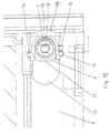
- Figure 3 is a section through the left corner of a first embodiment of a housing according to the invention shown with a detent spring 2 and an eccentric 3.
- Figure 4 is a section through the left corner of a second embodiment of a housing according to the invention shown.
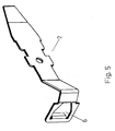
- FIG. 5 shows a first exemplary embodiment of a detent spring 2 in perspective view.
- a recess 6 for the engagement of the pin 7 of the eccentric 3 provided.
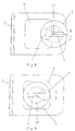
- Figure 6 shows the front of the first embodiment the detent spring 2 with the eccentric 3 in the locked position.
- the pin 7 lies on the right side wall of the recess 6 on.
- the eccentric 3 is at an angle of 180 ° rotatable to the right to the detent spring 2 in the unlocked state bring to.
- the slot is on the end face of the eccentric 3 4 intended for a screwdriver.
- Figure 7 shows the front of the first embodiment the detent spring 2 with the eccentric 3 in the unlocked position.
- the pin 7 of the eccentric 3 is also on the right side of the recess 6, but the eccentric 3 compared to Figure 6 rotated by 180 °, whereby the detent spring 2 has been moved to the right by path section A and thus is sunk in the housing.
- the eccentric 3 is rotatable about its axis of rotation 17. The direction of rotation is through the Arrow indicated. Because the width B of the recess 6 is smaller is chosen as the diameter of the eccentric, the Only turn the eccentric by 180 ° to the right or left.
- the recess 6 is used in the first embodiment of the Latch spring 2 not only as a device for engaging the Eccentric, but at the same time still acts as left and Right stop for locking and unlocking.
- FIG. 8 shows a second exemplary embodiment of the detent spring 2 shown in the locked state, while in Figure 9 in unlocked state is shown.
- the second embodiment the detent spring 2 differs from the first in that that the width B of the recess 6 is as large as the diameter of the eccentric is selected. With the same or larger as the diameter of the eccentric 3 chosen width B the Recess 6 the recess 6 no longer acts as a stop. Rather, the eccentric 3 can be moved endlessly to the right or turn left.
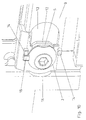
- FIG. 10 the left part of the front section is a third Embodiment of a housing according to the invention in perspective view shown.
- the eccentric 3 is rotatable with its groove 5 in an elongated hole 13 of the front 9 of the housing mounted. On the front 9 two opposing stops 14 are arranged. At the Eccentric 3, a stop 15 is provided, which in the unlocked Position on a stop 14 and in the locked Position on the other stop 14 of the front 9 of the housing is applied. On the circumference of the eccentric 3 is a chamfer 12 or two opposing chamfers 12 are incorporated.
- the housing by turning the Eccentric locked to the right, for example, while it is unlocked by turning the eccentric to the left.
- the eccentric to Locking and unlocking rotated 180 ° to the right or left be while in the first two embodiments is endlessly rotatable in both directions.
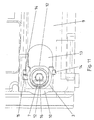
- FIG. 11 shows the left part of the front of the third embodiment of the housing according to the invention, while in the right part of the front is shown in FIG.
- the pin 7 of the eccentric 3 is through dashed lines indicated.
- a chamfer 12 is due to the left side wall 10 of the housing because of the eccentric 3 of the detent spring 2 against the left side wall 10 of the housing is pressed. This causes the detent spring 2 when turning the Eccentric 3 locking behavior.
- the eccentric 3 gives way in slot 13 towards the middle of the housing, but its edge always by the detent spring 2 against the left side wall 10 of the Housing pressed.
- Alternatively or at the same time can be provided a spring element that is chamfered on the other 12 presses. This spring element also generates a locking effect.
- a hexagon hole 16 provided for the engagement of an Allen key. The has provided for the storage of the eccentric 3 slot 13 also the advantage that the eccentric 3 and the detent spring 2nd are less tolerable.
- FIG. 13 shows an exemplary embodiment of a Eccentric shown in perspective.
- a Hexagon hole 16 for the engagement of an Allen key.
- the stop 15 At the The extent of the eccentric 3 are the stop 15 and the two opposing chamfers 12 are arranged.
- the annular groove 5 serves the rotatable mounting of the eccentric in the holding hole 11 or the slot 13 of the front 9 of the housing 1.
- the housing according to the invention is generally for installation in a Installation frame or a recess suitable. It can be easily in the mounting frame by means of the catch springs and the eccentric Lock and unlock or unlock the slot. For this are no special tools required. Particularly advantageous is the housing according to the invention for a car radio in which also a cassette device can be integrated, suitable because the fastening device according to the invention with the detent springs and the eccentrics consist of only a few parts and only takes up little space and because the light for motor vehicles Dimensions of the installation frame or installation slot are standardized. Because of the direct hand or by means of a usual Tool rotatable eccentric is the installation and removal of a Car radios possible with just a few simple steps.
Landscapes
- Engineering & Computer Science (AREA)
- Mechanical Engineering (AREA)
- Casings For Electric Apparatus (AREA)
- Structure Of Receivers (AREA)
- Connection Of Plates (AREA)
- Clamps And Clips (AREA)
- Fittings On The Vehicle Exterior For Carrying Loads, And Devices For Holding Or Mounting Articles (AREA)
Abstract
Description
- Figur 1
- ein Gehäuse mit zwei Rastfedern,
- Figur 2
- eine Seitenansicht des Gehäuses aus Figur 1,
- Figur 3
- einen Schnitt durch eine Ecke eines ersten Ausführungsbeispieles eines erfindungsgemäßen Gehäuses mit einer Rastfeder und einem Exzenter im verriegelten Zustand,
- Figur 4
- einen Schnitt durch eine Ecke eines zweiten Ausführungsbeispieles eines erfindungsgemäßen Gehäuses mit einer Rastfeder und einem Exzenter, wobei die Rastfeder im verriegelten und im entriegelten Zustand gezeigt ist,
- Figur 5
- ein erstes Ausführungsbeispiel einer Rastfeder in perspektivischer Ansicht,
- Figur 6
- eine Stirnansicht des ersten Ausführungsbeispiels der Rastfeder mit dem Exzenter im verriegelten Zustand,
- Figur 7
- eine Stirnansicht des ersten Ausführungsbeispiels der Rastfeder mit dem Exzenter im entriegelten Zustand,
- Figur 8
- eine Stirnansicht eines zweiten Ausführungsbeispieles der Rastfeder mit dem Exzenter im verriegelten Zustand,
- Figur 9
- eine Stirnansicht des zweiten Ausführungsbeispieles der Rastfeder mit dem Exzenter im entriegelten Zustand,
- Figur 10
- einen Ausschnitt aus der Frontseite eines in einen Rahmen eingebauten Autoradios mit einem dritten Ausführungsbeispiel eines erfindungsgemäßen Gehäuses in perspektivischer Darstellung,
- Figur 11
- den linken Teil der Frontseite eines in einen Rahmen eingesetzten Autoradios mit einem dritten Ausführungsbeispiel des erfindungsgemäßen Gehäuses,
- Figur 12
- den rechten Teil der Frontseite des in einen Rahmen eingesetzten Autoradios mit einem dritten Ausführungsbeispiel des erfindungsgemäßen Gehäuses und
- Figur 13
- einen Exzenter.
- 1
- Gehäuse
- 2
- Rastfeder
- 3
- Exzenter
- 4
- Schlitz
- 5
- Nut
- 6
- Aussparung
- 7
- Zapfen
- 8
- Seitenwand
- 9
- Frontseite
- 10
- Seitenwand des Gehäuses
- 11
- Halteloch
- 12
- Anfasung
- 13
- Langloch
- 14
- Anschlag am Gehäuse
- 15
- Anschlag am Exzenter
- 16
- Sechskantloch
- 17
- Drehachse
Claims (17)
- Gehäuse (1) mit mindestens einer aus dem Gehäuse (1) ragenden Rastfeder (2), die zum Einschieben des Gehäuses (1) in einen Einbaurahmen oder einen Einbauschacht und zum Entriegeln in das Gehäuse (1) versenkbar ist,
dadurch gekennzeichnet, dass ein unmittelbar von Hand oder mittels eines Werkzeuges drehbarer Exzenter (3) im Eingriff mit der Rastfeder (2) steht und dass die Rastfeder (2) durch Drehen des Exzenters (3) in den Verriegelungszustand, in welchem sie aus dem Gehäuse (1) ragt, und in den Entriegelungszustand, in welchem sie in das Gehäuse (1) versenkt ist, versetzbar ist. - Gehäuse nach Anspruch 1,
dadurch gekennzeichnet, dass an der rechten und der linken Seite des Gehäuses (1) je eine Rastfeder (2) und je ein Exzenter (3) angeordnet sind. - Gehäuse nach Anspruch 1 oder 2,
dadurch gekennzeichnet, dass an der Rastfeder (2) für den Eingriff des Exzenters (3) eine Aussparung (6), eine Kante oder ein Haken vorgesehen ist. - Gehäuse nach Anspruch 3,
dadurch gekennzeichnet, dass die Breite B der Aussparung (6) kleiner als der Durchmesser des Exzenters (3) gewählt ist, um einen Rechts- und einen Linksabschlag für den Exzenter (3) zu bilden. - Gehäuse nach Anspruch 3,
dadurch gekennzeichnet, dass die Breite B der Aussparung (6) gleich wie oder größer als der Durchmesser des Exzenters (3) gewählt ist, so dass der Exzenter (3) in beide Drehrichtungen endlos drehbar ist. - Gehäuse nach einem der Ansprüche 1 bis 5,
dadurch gekennzeichnet, dass der Exzenter (3) einen Handgriff zum Drehen von Hand aufweist. - Gehäuse nach einem der Ansprüche 1 bis 5,
dadurch gekennzeichnet, dass der Exzenter (3) eine Vorrichtung (4, 16) zum Eingreifen für ein übliches Werkzeug aufweist. - Gehäuse nach Anspruch 7,
dadurch gekennzeichnet, dass der Exzenter (3) einen Schlitz (4) für den Eingriff eines Schraubendrehers aufweist. - Gehäuse nach Anspruch 7,
dadurch gekennzeichnet, dass der Exzenter (3) eine Ausnehmung für den Eingriff eines Torx-Schraubendrehers aufweist. - Gehäuse nach Anspruch 7,
dadurch gekennzeichnet, dass der Exzenter (3) einen Sechskantkopf für den Eingriff eines Schraubenschlüssels aufweist. - Gehäuse nach Anspruch 7,
dadurch gekennzeichnet, dass der Exzenter (3) ein Sechskantloch (16) für den Eingriff eines Inbusschlüssels aufweist. - Gehäuse nach einem der Ansprüche 1 bis 11,
dadurch gekennzeichnet, dass eine ringförmige Nut (5) am Umfang des Exzenters (3) vorgesehen ist und in einem Halteloch (11) oder Langloch (13) des Gehäuses (1) geführt ist. - Gehäuse nach einem der Ansprüche 1 bis 12,
dadurch gekennzeichnet, dass am Exzenter (3) eine Anfasung (12) oder zwei einander gegenüberliegende Anfasungen (12) eingearbeitet sind und dass auf mindestens eine der beiden Anfasungen (12) eine Feder (2) drückt, um beim Drehen des Exzenters (3) Rastverhalten zu erzeugen. - Gehäuse nach einem der Ansprüche 1 bis 12,
dadurch gekennzeichnet, dass am Exzenter (3) eine Anfasung (12) oder zwei einander gegenüberliegende Anfasungen (12) eingearbeitet sind und dass die Rastfeder (2) den Exzenter (3) gegen eine Seitenwand (10) des Gehäuses (1) drückt, um beim Drehen des Exzenters (3) Rastverhalten zu erzeugen. - Gehäuse nach einem der Ansprüche 1 bis 3 oder 5 bis 12,
dadurch gekennzeichnet, dass der Exzenter (3) ohne einen Anschlag ausgeführt und endlos nach rechts und links drehbar ist. - Gehäuse nach einem der Ansprüche 1 bis 14,
dadurch gekennzeichnet, dass am Exzenter (3) ein Anschlag (15) und am Gehäuse (1) zwei Anschläge (14) für den Verriegelungszustand und den Entriegelungszustand vorgesehen sind. - Gehäuse nach einem der vorangehenden Ansprüche,
dadurch gekennzeichnet, dass es sich bei dem Gehäuse (1) um ein Gehäuse für ein Autoradio handelt.
Applications Claiming Priority (2)
| Application Number | Priority Date | Filing Date | Title |
|---|---|---|---|
| DE10036853 | 2000-07-28 | ||
| DE10036853A DE10036853C2 (de) | 2000-07-28 | 2000-07-28 | Gehäuse mit einer Befestigungsvorrichtung mit mindestens einer aus dem Gehäuse ragenden Rastfeder |
Publications (3)
| Publication Number | Publication Date |
|---|---|
| EP1176058A2 true EP1176058A2 (de) | 2002-01-30 |
| EP1176058A3 EP1176058A3 (de) | 2004-05-19 |
| EP1176058B1 EP1176058B1 (de) | 2005-09-21 |
Family
ID=7650566
Family Applications (1)
| Application Number | Title | Priority Date | Filing Date |
|---|---|---|---|
| EP01117318A Expired - Lifetime EP1176058B1 (de) | 2000-07-28 | 2001-07-18 | Gehäuse mit einer Befestigungsvorrichtung mit mindestens einer aus dem Gehäuse ragenden Rastfeder |
Country Status (3)
| Country | Link |
|---|---|
| EP (1) | EP1176058B1 (de) |
| AT (1) | ATE304959T1 (de) |
| DE (2) | DE10036853C2 (de) |
Cited By (2)
| Publication number | Priority date | Publication date | Assignee | Title |
|---|---|---|---|---|
| WO2008006441A3 (de) * | 2006-07-13 | 2008-04-17 | Hirschmann Car Comm Gmbh | Rastelement zur befestigung eines gehäuses eines hochfrequenztechnischen gerätes eines fahrzeuges an einem halter |
| DE102012019086A1 (de) | 2012-09-27 | 2014-03-27 | Volkswagen Ag | Vorrichtung und Verfahren zur Anbringung eines Geräts in der Instrumententafel eines Kraftfahrzeugs |
Families Citing this family (3)
| Publication number | Priority date | Publication date | Assignee | Title |
|---|---|---|---|---|
| DE10236814A1 (de) * | 2002-08-10 | 2004-02-19 | Marquardt Gmbh | Gehäuse für ein Schalterbedienfeld |
| DE102014007237A1 (de) | 2014-05-16 | 2015-11-19 | Leopold Kostal Gmbh & Co. Kg | Modulgehäuse und Bedienanordnung mit einem Modulgehäuse |
| DE102016102612A1 (de) | 2016-02-15 | 2017-08-17 | Phoenix Contact Gmbh & Co. Kg | Trägeranordnung zum Tragen eines Elektronikgehäuses |
Family Cites Families (4)
| Publication number | Priority date | Publication date | Assignee | Title |
|---|---|---|---|---|
| JPS5713835Y2 (de) * | 1976-05-18 | 1982-03-19 | ||
| DD146137B1 (de) * | 1979-09-26 | 1984-10-03 | Ulrich Hetzer | Verbindungs-und verriegelungseinrichtung fuer geraeteeinschuebe der nachrichtentechnik |
| DE9206965U1 (de) * | 1992-05-22 | 1992-08-13 | Blaupunkt-Werke Gmbh, 3200 Hildesheim | Autoradio mit einer Befestigungsvorrichtung |
| DE19614781C2 (de) * | 1996-04-04 | 1999-08-05 | Becker Gmbh | Befestigungssystem für Autoradios |
-
2000
- 2000-07-28 DE DE10036853A patent/DE10036853C2/de not_active Expired - Fee Related
-
2001
- 2001-07-18 AT AT01117318T patent/ATE304959T1/de not_active IP Right Cessation
- 2001-07-18 EP EP01117318A patent/EP1176058B1/de not_active Expired - Lifetime
- 2001-07-18 DE DE50107465T patent/DE50107465D1/de not_active Expired - Lifetime
Non-Patent Citations (1)
| Title |
|---|
| None |
Cited By (4)
| Publication number | Priority date | Publication date | Assignee | Title |
|---|---|---|---|---|
| WO2008006441A3 (de) * | 2006-07-13 | 2008-04-17 | Hirschmann Car Comm Gmbh | Rastelement zur befestigung eines gehäuses eines hochfrequenztechnischen gerätes eines fahrzeuges an einem halter |
| JP2009542511A (ja) * | 2006-07-13 | 2009-12-03 | ヒルシュマン カー コミュニケーション ゲゼルシャフト ミット ベシュレンクテル ハフツング | 車両の高周波技術機器のケーシングを保持体に固定するための係止部材 |
| DE102012019086A1 (de) | 2012-09-27 | 2014-03-27 | Volkswagen Ag | Vorrichtung und Verfahren zur Anbringung eines Geräts in der Instrumententafel eines Kraftfahrzeugs |
| DE102012019086B4 (de) | 2012-09-27 | 2021-12-30 | Volkswagen Ag | Vorrichtung und Verfahren zur Anbringung eines Geräts in der Instrumententafel eines Kraftfahrzeugs |
Also Published As
| Publication number | Publication date |
|---|---|
| EP1176058B1 (de) | 2005-09-21 |
| ATE304959T1 (de) | 2005-10-15 |
| DE50107465D1 (de) | 2005-10-27 |
| DE10036853A1 (de) | 2002-02-28 |
| DE10036853C2 (de) | 2002-10-10 |
| EP1176058A3 (de) | 2004-05-19 |
Similar Documents
| Publication | Publication Date | Title |
|---|---|---|
| DE10013111B4 (de) | Adapterplatte und System zur Anbringung eines Bauelementes auf eine Montageunterlage | |
| DE10049218C2 (de) | Elektronikgehäusesystem | |
| DE10296450T5 (de) | Druckschloß | |
| EP0175049A2 (de) | Steckschlüsselbetätigbarer Vorreiberverschluss | |
| EP3535824B1 (de) | Sammelschienenhalter und eine entsprechende anordnung | |
| EP1176058A2 (de) | Gehäuse mit einer Befestigungsvorrichtung mit mindestens einer aus dem Gehäuse ragenden Rastfeder | |
| EP1689078B1 (de) | Einrichtung zum Absorbieren des elektrischen Rauschens | |
| EP1272720B1 (de) | Zylinderschloss mit zylindergehäuse und flachschlüssel für ein zylinderschloss | |
| DE19520038A1 (de) | Zylinderanordnung für ein Plattenzuhaltungsschloß | |
| WO2018162114A1 (de) | Snapverbinder | |
| DE19505986C2 (de) | Klemmverbindung, insbesondere zur Festlegung von Gehäuseteilen elektrischer Geräte und Verschlußelement dafür | |
| EP2023765B1 (de) | Koffer, der nur bei geschlossenem deckel verriegelt werden kann | |
| DE10036398A1 (de) | Vorrichtung zur Arretierung eines Schließzylindergehäuses | |
| DE202015002795U1 (de) | Verriegelungsvorrichtung einer Steckbaugruppe | |
| EP1253046B1 (de) | Gehäuse | |
| DE102014111399B4 (de) | Lenkradschlosseinrichtung | |
| DE10005136A1 (de) | Schließzylinder, insbesondere für Kfz | |
| EP0791704A1 (de) | Schliessblech | |
| DE69905956T2 (de) | Zylinderschloss | |
| DE102008049808A1 (de) | Schlüssel mit einem ersten Teil und einem zweiten Teil | |
| DE3508160C1 (de) | Lenkschloß für Kraftfahrzeuge | |
| DE3505190A1 (de) | Verriegelungsvorrichtung fuer einschiebbare baugruppen | |
| DE102011088800A1 (de) | Bedienelement, insbesondere für ein Kraftfahrzeug | |
| EP1460212A2 (de) | Vorhangschloss | |
| EP0523401A1 (de) | Türsicherung für ein mit einem Türfeststeller baulich vereinigtes Türscharnier |
Legal Events
| Date | Code | Title | Description |
|---|---|---|---|
| PUAI | Public reference made under article 153(3) epc to a published international application that has entered the european phase |
Free format text: ORIGINAL CODE: 0009012 |
|
| AK | Designated contracting states |
Kind code of ref document: A2 Designated state(s): AT BE CH CY DE DK ES FI FR GB GR IE IT LI LU MC NL PT SE TR |
|
| AX | Request for extension of the european patent |
Free format text: AL;LT;LV;MK;RO;SI |
|
| PUAL | Search report despatched |
Free format text: ORIGINAL CODE: 0009013 |
|
| AK | Designated contracting states |
Kind code of ref document: A3 Designated state(s): AT BE CH CY DE DK ES FI FR GB GR IE IT LI LU MC NL PT SE TR |
|
| AX | Request for extension of the european patent |
Extension state: AL LT LV MK RO SI |
|
| 17P | Request for examination filed |
Effective date: 20040527 |
|
| 17Q | First examination report despatched |
Effective date: 20040820 |
|
| AKX | Designation fees paid |
Designated state(s): AT BE CH CY DE DK ES FI FR GB GR IE IT LI LU MC NL PT SE TR |
|
| GRAP | Despatch of communication of intention to grant a patent |
Free format text: ORIGINAL CODE: EPIDOSNIGR1 |
|
| GRAS | Grant fee paid |
Free format text: ORIGINAL CODE: EPIDOSNIGR3 |
|
| GRAA | (expected) grant |
Free format text: ORIGINAL CODE: 0009210 |
|
| AK | Designated contracting states |
Kind code of ref document: B1 Designated state(s): AT BE CH CY DE DK ES FI FR GB GR IE IT LI LU MC NL PT SE TR |
|
| PG25 | Lapsed in a contracting state [announced via postgrant information from national office to epo] |
Ref country code: NL Free format text: LAPSE BECAUSE OF FAILURE TO SUBMIT A TRANSLATION OF THE DESCRIPTION OR TO PAY THE FEE WITHIN THE PRESCRIBED TIME-LIMIT Effective date: 20050921 Ref country code: FI Free format text: LAPSE BECAUSE OF FAILURE TO SUBMIT A TRANSLATION OF THE DESCRIPTION OR TO PAY THE FEE WITHIN THE PRESCRIBED TIME-LIMIT Effective date: 20050921 Ref country code: IE Free format text: LAPSE BECAUSE OF FAILURE TO SUBMIT A TRANSLATION OF THE DESCRIPTION OR TO PAY THE FEE WITHIN THE PRESCRIBED TIME-LIMIT Effective date: 20050921 |
|
| REG | Reference to a national code |
Ref country code: GB Ref legal event code: FG4D Free format text: NOT ENGLISH |
|
| REG | Reference to a national code |
Ref country code: CH Ref legal event code: EP |
|
| REG | Reference to a national code |
Ref country code: IE Ref legal event code: FG4D Free format text: LANGUAGE OF EP DOCUMENT: GERMAN |
|
| REF | Corresponds to: |
Ref document number: 50107465 Country of ref document: DE Date of ref document: 20051027 Kind code of ref document: P |
|
| PG25 | Lapsed in a contracting state [announced via postgrant information from national office to epo] |
Ref country code: SE Free format text: LAPSE BECAUSE OF FAILURE TO SUBMIT A TRANSLATION OF THE DESCRIPTION OR TO PAY THE FEE WITHIN THE PRESCRIBED TIME-LIMIT Effective date: 20051221 Ref country code: DK Free format text: LAPSE BECAUSE OF FAILURE TO SUBMIT A TRANSLATION OF THE DESCRIPTION OR TO PAY THE FEE WITHIN THE PRESCRIBED TIME-LIMIT Effective date: 20051221 Ref country code: GR Free format text: LAPSE BECAUSE OF FAILURE TO SUBMIT A TRANSLATION OF THE DESCRIPTION OR TO PAY THE FEE WITHIN THE PRESCRIBED TIME-LIMIT Effective date: 20051221 |
|
| PG25 | Lapsed in a contracting state [announced via postgrant information from national office to epo] |
Ref country code: ES Free format text: LAPSE BECAUSE OF FAILURE TO SUBMIT A TRANSLATION OF THE DESCRIPTION OR TO PAY THE FEE WITHIN THE PRESCRIBED TIME-LIMIT Effective date: 20060101 |
|
| GBT | Gb: translation of ep patent filed (gb section 77(6)(a)/1977) |
Effective date: 20060119 |
|
| PG25 | Lapsed in a contracting state [announced via postgrant information from national office to epo] |
Ref country code: PT Free format text: LAPSE BECAUSE OF FAILURE TO SUBMIT A TRANSLATION OF THE DESCRIPTION OR TO PAY THE FEE WITHIN THE PRESCRIBED TIME-LIMIT Effective date: 20060221 |
|
| NLV1 | Nl: lapsed or annulled due to failure to fulfill the requirements of art. 29p and 29m of the patents act | ||
| REG | Reference to a national code |
Ref country code: IE Ref legal event code: FD4D |
|
| ET | Fr: translation filed | ||
| PGFP | Annual fee paid to national office [announced via postgrant information from national office to epo] |
Ref country code: MC Payment date: 20060704 Year of fee payment: 6 |
|
| PGFP | Annual fee paid to national office [announced via postgrant information from national office to epo] |
Ref country code: AT Payment date: 20060705 Year of fee payment: 6 |
|
| PGFP | Annual fee paid to national office [announced via postgrant information from national office to epo] |
Ref country code: CH Payment date: 20060727 Year of fee payment: 6 |
|
| PLBE | No opposition filed within time limit |
Free format text: ORIGINAL CODE: 0009261 |
|
| STAA | Information on the status of an ep patent application or granted ep patent |
Free format text: STATUS: NO OPPOSITION FILED WITHIN TIME LIMIT |
|
| PGFP | Annual fee paid to national office [announced via postgrant information from national office to epo] |
Ref country code: LU Payment date: 20060804 Year of fee payment: 6 |
|
| PGFP | Annual fee paid to national office [announced via postgrant information from national office to epo] |
Ref country code: BE Payment date: 20060828 Year of fee payment: 6 |
|
| 26N | No opposition filed |
Effective date: 20060622 |
|
| BERE | Be: lapsed |
Owner name: BECKER G.M.B.H. Effective date: 20070731 |
|
| REG | Reference to a national code |
Ref country code: CH Ref legal event code: PL |
|
| PG25 | Lapsed in a contracting state [announced via postgrant information from national office to epo] |
Ref country code: MC Free format text: LAPSE BECAUSE OF NON-PAYMENT OF DUE FEES Effective date: 20070731 Ref country code: CH Free format text: LAPSE BECAUSE OF NON-PAYMENT OF DUE FEES Effective date: 20070731 Ref country code: LI Free format text: LAPSE BECAUSE OF NON-PAYMENT OF DUE FEES Effective date: 20070731 |
|
| PG25 | Lapsed in a contracting state [announced via postgrant information from national office to epo] |
Ref country code: AT Free format text: LAPSE BECAUSE OF NON-PAYMENT OF DUE FEES Effective date: 20070718 |
|
| PG25 | Lapsed in a contracting state [announced via postgrant information from national office to epo] |
Ref country code: TR Free format text: LAPSE BECAUSE OF FAILURE TO SUBMIT A TRANSLATION OF THE DESCRIPTION OR TO PAY THE FEE WITHIN THE PRESCRIBED TIME-LIMIT Effective date: 20050921 |
|
| PG25 | Lapsed in a contracting state [announced via postgrant information from national office to epo] |
Ref country code: BE Free format text: LAPSE BECAUSE OF NON-PAYMENT OF DUE FEES Effective date: 20070731 |
|
| PG25 | Lapsed in a contracting state [announced via postgrant information from national office to epo] |
Ref country code: CY Free format text: LAPSE BECAUSE OF FAILURE TO SUBMIT A TRANSLATION OF THE DESCRIPTION OR TO PAY THE FEE WITHIN THE PRESCRIBED TIME-LIMIT Effective date: 20050921 |
|
| PG25 | Lapsed in a contracting state [announced via postgrant information from national office to epo] |
Ref country code: LU Free format text: LAPSE BECAUSE OF NON-PAYMENT OF DUE FEES Effective date: 20070718 |
|
| PGFP | Annual fee paid to national office [announced via postgrant information from national office to epo] |
Ref country code: FR Payment date: 20140717 Year of fee payment: 14 |
|
| PGFP | Annual fee paid to national office [announced via postgrant information from national office to epo] |
Ref country code: IT Payment date: 20140724 Year of fee payment: 14 |
|
| PG25 | Lapsed in a contracting state [announced via postgrant information from national office to epo] |
Ref country code: IT Free format text: LAPSE BECAUSE OF NON-PAYMENT OF DUE FEES Effective date: 20150718 |
|
| REG | Reference to a national code |
Ref country code: FR Ref legal event code: ST Effective date: 20160331 |
|
| PG25 | Lapsed in a contracting state [announced via postgrant information from national office to epo] |
Ref country code: FR Free format text: LAPSE BECAUSE OF NON-PAYMENT OF DUE FEES Effective date: 20150731 |
|
| PGFP | Annual fee paid to national office [announced via postgrant information from national office to epo] |
Ref country code: GB Payment date: 20160727 Year of fee payment: 16 Ref country code: DE Payment date: 20160726 Year of fee payment: 16 |
|
| REG | Reference to a national code |
Ref country code: DE Ref legal event code: R119 Ref document number: 50107465 Country of ref document: DE |
|
| GBPC | Gb: european patent ceased through non-payment of renewal fee |
Effective date: 20170718 |
|
| PG25 | Lapsed in a contracting state [announced via postgrant information from national office to epo] |
Ref country code: GB Free format text: LAPSE BECAUSE OF NON-PAYMENT OF DUE FEES Effective date: 20170718 Ref country code: DE Free format text: LAPSE BECAUSE OF NON-PAYMENT OF DUE FEES Effective date: 20180201 |