EP1175952A1 - Verfahren zum Verbinden von Werkstücken - Google Patents
Verfahren zum Verbinden von Werkstücken Download PDFInfo
- Publication number
- EP1175952A1 EP1175952A1 EP01000317A EP01000317A EP1175952A1 EP 1175952 A1 EP1175952 A1 EP 1175952A1 EP 01000317 A EP01000317 A EP 01000317A EP 01000317 A EP01000317 A EP 01000317A EP 1175952 A1 EP1175952 A1 EP 1175952A1
- Authority
- EP
- European Patent Office
- Prior art keywords
- anode
- section
- style
- workpiece
- cross
- Prior art date
- Legal status (The legal status is an assumption and is not a legal conclusion. Google has not performed a legal analysis and makes no representation as to the accuracy of the status listed.)
- Ceased
Links
Images

Classifications
-
- B—PERFORMING OPERATIONS; TRANSPORTING
- B23—MACHINE TOOLS; METAL-WORKING NOT OTHERWISE PROVIDED FOR
- B23K—SOLDERING OR UNSOLDERING; WELDING; CLADDING OR PLATING BY SOLDERING OR WELDING; CUTTING BY APPLYING HEAT LOCALLY, e.g. FLAME CUTTING; WORKING BY LASER BEAM
- B23K20/00—Non-electric welding by applying impact or other pressure, with or without the application of heat, e.g. cladding or plating
- B23K20/12—Non-electric welding by applying impact or other pressure, with or without the application of heat, e.g. cladding or plating the heat being generated by friction; Friction welding
-
- B—PERFORMING OPERATIONS; TRANSPORTING
- B23—MACHINE TOOLS; METAL-WORKING NOT OTHERWISE PROVIDED FOR
- B23K—SOLDERING OR UNSOLDERING; WELDING; CLADDING OR PLATING BY SOLDERING OR WELDING; CUTTING BY APPLYING HEAT LOCALLY, e.g. FLAME CUTTING; WORKING BY LASER BEAM
- B23K20/00—Non-electric welding by applying impact or other pressure, with or without the application of heat, e.g. cladding or plating
- B23K20/12—Non-electric welding by applying impact or other pressure, with or without the application of heat, e.g. cladding or plating the heat being generated by friction; Friction welding
- B23K20/129—Non-electric welding by applying impact or other pressure, with or without the application of heat, e.g. cladding or plating the heat being generated by friction; Friction welding specially adapted for particular articles or work
-
- H—ELECTRICITY
- H01—ELECTRIC ELEMENTS
- H01J—ELECTRIC DISCHARGE TUBES OR DISCHARGE LAMPS
- H01J35/00—X-ray tubes
- H01J35/02—Details
- H01J35/04—Electrodes ; Mutual position thereof; Constructional adaptations therefor
- H01J35/08—Anodes; Anti cathodes
- H01J35/10—Rotary anodes; Arrangements for rotating anodes; Cooling rotary anodes
- H01J35/101—Arrangements for rotating anodes, e.g. supporting means, means for greasing, means for sealing the axle or means for shielding or protecting the driving
Definitions
- the invention relates to a method for connecting a first workpiece to a second workpiece, such as an anode style with an end plate of a rotor shell in a rotating anode x-ray tube.
- Rotating anode X-ray tubes include a device for electron beam generation as essential components a rotor shell, which at one end with an end plate is completed, as well as an anode style (anode shaft) attached to it, the one Anode plate (rotating anode) carries.
- the rotor shell is generally made of copper
- the end plate is made of an iron-nickel-cobalt alloy (FerNiCo) or made of nickel 42
- the anode style is in many cases made of a tungsten-zirconium-molybdenum alloy (TZM).
- the connection the anode style with the faceplate is generally done by soldering with a high temperature solder.
- the materials mentioned have very different melting points, so that the solder joint is common due to solder gaps, bonding defects, etc. is faulty.
- the rotor and in particular the anode style are impacted or Unbalance of the turning system can be exposed to high mechanical loads high demands are placed on this connection in particular.
- DE-OS 29 15 418 describes a method for connecting workpieces Materials with very different melting points known, in which the connecting surfaces the workpieces mechanically brought together by friction welding and then finally joined together by diffusion welding.
- An essential one Disadvantage of this method, however, is that it has two welding processes relatively complex and the quality or strength of the connection in many Cases is not reproducible.
- An essential object on which the invention is based is therefore a Method for connecting a first workpiece to a second workpiece create with which these workpieces, such as an anode handle and a face plate in a rotating anode X-ray tube, in a reproducible manner with high strength with each other can be connected.
- the breaking strength is therefore no longer due to the friction weld connection and a Possibly influenced and hardly predictable material influence, but alone given by the strength of the section with reduced cross-section.
- This one Strength only depends on the type of material used and the cross-section itself , the strength of the connection achieved according to the invention is more reliable Way reproducible.
- the reduction in cross section also increases the thermal conductivity reduced, which is for the application mentioned in the anode X-ray tubes is particularly advantageous.
- the cross-section is only made as large as to achieve it the strength necessary for safe operation is absolutely necessary.
- the cross-sectional reduction thus advantageously combines two different ones Functions.
- Another advantage is that the method can also be used to connect workpieces from materials with very different melting points is suitable because one any resulting impairment of the strength of the friction weld a correspondingly greater reduction in the cross section relative to that of the Connection area can be taken into account to accomplish the task mentioned to solve.
- the process can also be carried out in such a way that the cross-section on at least one of the workpieces reduced and then the friction welding is carried out.
- the training according to claim 2 is useful because the heat generated by the friction welding the material to the welded Can weaken areas adjacent areas of the workpieces.
- Claim 4 finally describes a particularly preferred application for the inventive method.
- a rotating anode X-ray tube comprises a tube bulb 1 in which a cathode arrangement 3 for generating an electron beam and opposite each other this is a rotating anode arrangement.
- This arrangement essentially comprises a rotating anode plate 4, which is interchangeably mounted at one end of an anode shaft 5 is.
- the other end of the anode stem 5 is cylindrical with an end plate 6 Rotor shell 7 connected.
- the electron beam generated by the cathode arrangement 3 falls on the oblique Section of the anode plate 4 and thereby generates an X-ray radiation through a Exit window 2 leaves tube 1.
- the anode plate 4 is in a known manner via the anode style 5 and the rotor jacket 7 rotated to avoid overheating of the anode plate 4.
- the anode style 5 must transmit the rotary movement on the one hand and the anode plate 4 also safe when subjected to impacts or an imbalance of the turning system hold, but on the other hand also serve as a heat barrier in order, as explained at the beginning, to prevent excessive heat flow into the rotor shell and the drive system.
- the anode style 5 is generally attached to the anode plate 4 by a screw connection and is not critical in this respect. To meet the above requirements to meet, the anode style 5 on the end plate 6 according to an inventive Procedure attached.
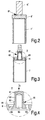
- Figure 2 shows the relevant components in a raw state, namely one Rotor jacket 7 'with an end plate 6' placed thereon and a solid style 5 '.
- the style 5 ', the end plate 6' and the rotor jacket 7 ' are first of all by friction welding connected with each other.
- the connecting surface created by the friction welding between style 5 'and face plate 6' is 81 designated.
- FIG. 3 The configuration shown in FIG. 3 is then formed from this. According to the enlarged The area 61 delineated there with dashed lines is shown in detail in FIG the end plate 6 'and a region 51 delimited by dashed lines on the circumference of the style 5' abraded or otherwise removed so that a section 52 with a reduced cross section.
- connection area 82 which connects the connection surface 81 and heat-affected zones around this connecting surface 81.
- the heat affected zones are the zones in which the properties of the material, especially its Strength that can affect the heat generated during friction welding.
- the face plate 6 'and the style 5' are also with a common bore 83 Mistake. Further holes 62, 63, which are made in the end plate 6, are used for mounting the turning system.
- the wall thickness of the connection area 82 is thus greater than the wall thickness of section 52 on the (finished) anode style 5.
- connection area 82 and Section 52 The dimensioning of the relative wall thicknesses of the connection area 82 and the Section 52 is carried out so that the following requirements are met:
- section 52 is only made as strong as it is to achieve a sufficient strength for the transmission of the rotary motion to the anode plate 4 taking into account possible shock loads and unbalance of the Turning system is absolutely necessary. This ensures that the heat flow is off the anode plate 4 in the rotor jacket 7 and the drive system as low as possible is held.
- the wall thickness of the connection area 82 is chosen so large that the Strength of this area is greater than the strength of section 52.
- the required Wall thickness depends in particular on the extent to which the strength of the used Material affected in the heat affected zone created by the friction welding is. In the case of TZM (Tungsten Zirconium Molybdenum), which is often used for manufacturing the anode style is used, the strength is halved in this, for example Heat affected zone. This means that the wall thickness in the connection area 82 must be at least twice as large as the wall thickness in section 52.
- connection according to the invention thus fulfills both the requirement for adequate Strength only by the type of 5 used for the anode style Material and wall thickness of section 52 is determined as well as the requirement after the lowest possible thermal conductivity, i.e. a thermal barrier to protect the Rotation system against excessive heating
Landscapes
- Engineering & Computer Science (AREA)
- Mechanical Engineering (AREA)
- X-Ray Techniques (AREA)
- Turbine Rotor Nozzle Sealing (AREA)
- Pressure Welding/Diffusion-Bonding (AREA)
Abstract
Description
- Reibschweißen des ersten Werkstücks an das zweite Werkstück;
- Vermindern des Querschnitts mindestens eines der beiden Werkstücke in einem Abschnitt außerhalb eines Verbindungsbereiches, in dem die Reibschweißung liegt, in der Weise, dass die Festigkeit des Verbindungsbereiches zumindest geringfügig größer ist, als diejenige des Abschnitts mit vermindertem Querschnitt.
Claims (6)
- Verfahren zum Verbinden eines ersten Werkstücks mit einem zweiten Werkstück mit folgenden Verfahrensschritten:Reibschweißen des ersten Werkstücks (6) an das zweite Werkstück (5);Vermindern des Querschnitts mindestens eines der beiden Werkstücke in einem Abschnitt (52) außerhalb eines Verbindungsbereiches (82), in dem die Reibschweißung liegt, in der Weise, dass die Festigkeit des Verbindungsbereiches (82) zumindest geringfügig größer ist, als diejenige des Abschnitts (52) mit vermindertem Querschnitt.
- Verfahren nach Anspruch 1,
dadurch gekennzeichnet, dass der Verbindungsbereich (82) eine durch die Reibschweißung entstandene Wärmeeinflusszone an mindestens einem der Werkstücke (5; 6) umfasst. - Verfahren nach Anspruch 1,
dadurch gekennzeichnet, dass mindestens eines der Werkstücke (6, 5) zur Querschnittsverminderung mit einer Bohrung (83) versehen wird. - Verfahren nach Anspruch 1,
dadurch gekennzeichnet, dass das erste Werkstück (6) eine Stirnplatte eines Rotormantels (7) und das zweite Werkstück (5) ein Anodenstil zur Befestigung eines Anodentellers (4) in einer Drehanoden-Röntgenröhre ist, wobei der Querschnitt des Abschnitts (52) an dem zweiten Werkstück (5) durch Abdrehen so weit vermindert wird, dass bei noch ausreichender Festigkeit eine möglichst geringe Wärmeleitfähigkeit erzielt wird - Drehanoden-Röntgenröhre mit einem Anodenstil, der mit einer Stirnplatte eines Rotormantels verbunden ist,
dadurch gekennzeichnet, dass ein Verbindungsbereich (82), in dem der Anodenstil (5) mit der Stirnplatte (6) verbunden ist, einen größeren Durchmesser aufweist, als ein Abschnitt (52) an dem Anodenstil (5). - Drehanoden-Röntgenröhre nach Anspruch 5,
dadurch gekennzeichnet, dass die Verbindung zwischen dem Anodenstil (5) und der Stirnplatte (6) eine Reibschweißverbindung ist.
Applications Claiming Priority (2)
| Application Number | Priority Date | Filing Date | Title |
|---|---|---|---|
| DE10036614 | 2000-07-27 | ||
| DE10036614A DE10036614A1 (de) | 2000-07-27 | 2000-07-27 | Verfahren zum Verbinden von Werkstücken |
Publications (1)
| Publication Number | Publication Date |
|---|---|
| EP1175952A1 true EP1175952A1 (de) | 2002-01-30 |
Family
ID=7650412
Family Applications (1)
| Application Number | Title | Priority Date | Filing Date |
|---|---|---|---|
| EP01000317A Ceased EP1175952A1 (de) | 2000-07-27 | 2001-07-25 | Verfahren zum Verbinden von Werkstücken |
Country Status (4)
| Country | Link |
|---|---|
| US (1) | US6632118B2 (de) |
| EP (1) | EP1175952A1 (de) |
| JP (1) | JP2002117793A (de) |
| DE (1) | DE10036614A1 (de) |
Families Citing this family (7)
| Publication number | Priority date | Publication date | Assignee | Title |
|---|---|---|---|---|
| JP4628069B2 (ja) * | 2004-11-24 | 2011-02-09 | 京セラ株式会社 | 燃料改質器収納用容器および燃料改質装置 |
| DE102007010262A1 (de) * | 2007-03-02 | 2008-09-04 | Siemens Ag | Leichtbaustruktur |
| US8887388B2 (en) | 2010-11-22 | 2014-11-18 | Andrew Llc | Method for interconnecting a coaxial connector with a solid outer conductor coaxial cable |
| US8365404B2 (en) | 2010-11-22 | 2013-02-05 | Andrew Llc | Method for ultrasonic welding a coaxial cable to a coaxial connector |
| US8876549B2 (en) | 2010-11-22 | 2014-11-04 | Andrew Llc | Capacitively coupled flat conductor connector |
| US9768574B2 (en) | 2010-11-22 | 2017-09-19 | Commscope Technologies Llc | Cylindrical surface spin weld apparatus |
| US9972472B2 (en) * | 2014-11-10 | 2018-05-15 | General Electric Company | Welded spiral groove bearing assembly |
Citations (6)
| Publication number | Priority date | Publication date | Assignee | Title |
|---|---|---|---|---|
| US3429591A (en) * | 1967-09-06 | 1969-02-25 | Caterpillar Tractor Co | Precombustion chambers |
| US4119261A (en) * | 1977-04-18 | 1978-10-10 | General Electric Company | Inertia welding process for making an anode assembly |
| US4445265A (en) * | 1980-12-12 | 1984-05-01 | Smith International, Inc. | Shrink grip drill pipe fabrication method |
| WO1995032833A1 (en) * | 1994-05-31 | 1995-12-07 | General Electric Company | Method for friction welding a shaft to a disk and assembly formed thereby |
| DE29623218U1 (de) * | 1996-07-17 | 1998-02-19 | Siemens AG, 80333 München | Vakuumröhre |
| DE29623220U1 (de) * | 1996-07-17 | 1998-02-26 | Siemens AG, 80333 München | Vakuumröhre |
Family Cites Families (13)
| Publication number | Priority date | Publication date | Assignee | Title |
|---|---|---|---|---|
| US4187442A (en) * | 1978-09-05 | 1980-02-05 | General Electric Company | Rotating anode X-ray tube with improved thermal capacity |
| US4333671A (en) * | 1980-05-05 | 1982-06-08 | General Atomic Company | Friction welded transition joint |
| US4501566A (en) * | 1983-09-19 | 1985-02-26 | Technicare Corporation | Method for assembling a high vacuum rotating anode X-ray tube |
| US5088638A (en) * | 1985-11-26 | 1992-02-18 | Karaev Islam K O | Method for making sucker rods |
| US5930332A (en) * | 1996-12-03 | 1999-07-27 | General Electric Company | Method for connecting a molybdenum-based alloy structure to a structure formed from a more ductile alloy, and related articles |
| JP3897391B2 (ja) * | 1997-03-25 | 2007-03-22 | 昭和電工株式会社 | 金属製接合部材の摩擦撹拌接合法 |
| AT406205B (de) * | 1997-10-30 | 2000-03-27 | Plansee Ag | Verfahren zur herstellung einer drehanoden-baueinheit |
| JP3209170B2 (ja) * | 1997-12-02 | 2001-09-17 | 日本軽金属株式会社 | アルミニウム合金製中空部材の摩擦圧接方法及び継手 |
| US6051325A (en) * | 1997-12-23 | 2000-04-18 | Mcdonnell Douglas Corporation | Joining of machined sandwich assemblies by friction stir welding |
| JP2000074024A (ja) * | 1998-09-02 | 2000-03-07 | Tokai Rubber Ind Ltd | アーム用部材 |
| JP3663111B2 (ja) * | 1999-10-18 | 2005-06-22 | 株式会社東芝 | 回転陽極型x線管 |
| US6390875B1 (en) * | 2000-03-24 | 2002-05-21 | General Electric Company | Method for enhancing thermal radiation transfer in X-ray tube components |
| JP2002075260A (ja) * | 2000-06-15 | 2002-03-15 | Toshiba Corp | 回転陽極型x線管及びそれを備えたx線管装置 |
-
2000
- 2000-07-27 DE DE10036614A patent/DE10036614A1/de not_active Withdrawn
-
2001
- 2001-07-24 US US09/912,124 patent/US6632118B2/en not_active Expired - Fee Related
- 2001-07-25 EP EP01000317A patent/EP1175952A1/de not_active Ceased
- 2001-07-26 JP JP2001225524A patent/JP2002117793A/ja not_active Withdrawn
Patent Citations (6)
| Publication number | Priority date | Publication date | Assignee | Title |
|---|---|---|---|---|
| US3429591A (en) * | 1967-09-06 | 1969-02-25 | Caterpillar Tractor Co | Precombustion chambers |
| US4119261A (en) * | 1977-04-18 | 1978-10-10 | General Electric Company | Inertia welding process for making an anode assembly |
| US4445265A (en) * | 1980-12-12 | 1984-05-01 | Smith International, Inc. | Shrink grip drill pipe fabrication method |
| WO1995032833A1 (en) * | 1994-05-31 | 1995-12-07 | General Electric Company | Method for friction welding a shaft to a disk and assembly formed thereby |
| DE29623218U1 (de) * | 1996-07-17 | 1998-02-19 | Siemens AG, 80333 München | Vakuumröhre |
| DE29623220U1 (de) * | 1996-07-17 | 1998-02-26 | Siemens AG, 80333 München | Vakuumröhre |
Also Published As
| Publication number | Publication date |
|---|---|
| US20020029836A1 (en) | 2002-03-14 |
| DE10036614A1 (de) | 2002-02-07 |
| US6632118B2 (en) | 2003-10-14 |
| JP2002117793A (ja) | 2002-04-19 |
Similar Documents
| Publication | Publication Date | Title |
|---|---|---|
| DE102008044451B4 (de) | Konduktives Bolzenschweißen | |
| EP1719572B1 (de) | Verfahren zum Verschweißen eines Tellerrads mit einem Ausgleichsgehäuse eines Getriebes | |
| DE102013104222A1 (de) | Hybrides Schneidwerkzeug, Spantransportabschnitt sowie Verfahren zur Herstellung eines Schneidwerkzeugs | |
| EP4217619B1 (de) | Verfahren zur herstellung eines bauteiles eines gleitlagers, sowie bauteil, gleitlager und getriebe einer windkraftanlage | |
| DE102011114306A1 (de) | Verfahren zum Fügen von wenigstens zwei FVK-Bauteilen | |
| DE19800097A1 (de) | Span- oder Schneidwerkzeug und Verfahren zu dessen Herstellung | |
| EP1185390A1 (de) | Dehnspannwerkzeug | |
| DE19536027C2 (de) | Planetengetriebe-Geschwindigkeitsreduzierer und Herstellungsverfahren für einen Planetengetriebe-Haltestift für dasselbe | |
| DE60211159T2 (de) | Fahrzeugachsgehäuse und Verfahren und Vorrichtung zu seiner Herstellung | |
| EP1175952A1 (de) | Verfahren zum Verbinden von Werkstücken | |
| EP1606599B1 (de) | Federelastisches messelement mit flachem, verschweissbarem verbindungselement | |
| AT412041B (de) | Targetanordnung für eine röntgenröhre und verfahren zur herstellung derselben | |
| DE19634417A1 (de) | Verfahren zur Verbindung dünnwandiger Werkstücke | |
| DE102008027841A1 (de) | Verfahren zum Verbinden, insbesondere von einem äusseren Bauteil mit einem in dieses eingebrachtes inneres Bauteil | |
| DE102007009779C5 (de) | Drehverbindung zwischen Welle und Ritzel und Verfahren zu deren Herstellung | |
| DE102019203051A1 (de) | Befestigungselement zum Reibschweißen sowie Verfahren zum Reibschweißen eines Befestigungselements an ein flächiges Werkstück | |
| DE10039450B4 (de) | Verfahren zum Erneuern einer Schraubverbindung und Werkzeugsatz hierfür | |
| DE3306984A1 (de) | Supraleitender generator mit waermestrahlungsabschirmung | |
| DE102015203078A1 (de) | Fahrwerksaktuatorvorrichtung, insbesondere Wankstabilisator | |
| DE10144588C1 (de) | Befestigungsverfahren, Montagewerkzeug und Stützhebel für ein Schaltschloss eines Leistungsschalters, bzw. Lasttrennschalters | |
| DE3013441A1 (de) | Anodenteller fuer eine drehanoden-roentgenroehre und verfahren zu seiner herstellung | |
| EP3715665B1 (de) | Elektromagnetisch lüftbare federkraftbremse und verfahren zu deren herstellung | |
| DE102009040527A1 (de) | Werzeug zum Rührreibschweißen und Verfahren | |
| EP0066004A1 (de) | Ventilstössel | |
| EP4523498B1 (de) | Kupferkontaktbacke sowie verfahren zu ihrer herstellung |
Legal Events
| Date | Code | Title | Description |
|---|---|---|---|
| PUAI | Public reference made under article 153(3) epc to a published international application that has entered the european phase |
Free format text: ORIGINAL CODE: 0009012 |
|
| AK | Designated contracting states |
Kind code of ref document: A1 Designated state(s): AT BE CH CY DE DK ES FI FR GB GR IE IT LI LU MC NL PT SE TR Kind code of ref document: A1 Designated state(s): AT DE FR GB NL |
|
| AX | Request for extension of the european patent |
Free format text: AL;LT;LV;MK;RO;SI |
|
| 17P | Request for examination filed |
Effective date: 20020730 |
|
| RAP1 | Party data changed (applicant data changed or rights of an application transferred) |
Owner name: KONINKLIJKE PHILIPS ELECTRONICS N.V. Owner name: PHILIPS CORPORATE INTELLECTUAL PROPERTY GMBH |
|
| AKX | Designation fees paid |
Free format text: AT DE FR GB NL |
|
| RAP1 | Party data changed (applicant data changed or rights of an application transferred) |
Owner name: KONINKLIJKE PHILIPS ELECTRONICS N.V. Owner name: PHILIPS INTELLECTUAL PROPERTY & STANDARDS GMBH |
|
| 17Q | First examination report despatched |
Effective date: 20061026 |
|
| APBK | Appeal reference recorded |
Free format text: ORIGINAL CODE: EPIDOSNREFNE |
|
| APBN | Date of receipt of notice of appeal recorded |
Free format text: ORIGINAL CODE: EPIDOSNNOA2E |
|
| APAF | Appeal reference modified |
Free format text: ORIGINAL CODE: EPIDOSCREFNE |
|
| APBT | Appeal procedure closed |
Free format text: ORIGINAL CODE: EPIDOSNNOA9E |
|
| STAA | Information on the status of an ep patent application or granted ep patent |
Free format text: STATUS: THE APPLICATION HAS BEEN REFUSED |
|
| 18R | Application refused |
Effective date: 20100426 |