EP1174971A2 - Installationskanal - Google Patents
Installationskanal Download PDFInfo
- Publication number
- EP1174971A2 EP1174971A2 EP01108680A EP01108680A EP1174971A2 EP 1174971 A2 EP1174971 A2 EP 1174971A2 EP 01108680 A EP01108680 A EP 01108680A EP 01108680 A EP01108680 A EP 01108680A EP 1174971 A2 EP1174971 A2 EP 1174971A2
- Authority
- EP
- European Patent Office
- Prior art keywords
- installation
- duct
- cover
- profile
- scaling
- Prior art date
- Legal status (The legal status is an assumption and is not a legal conclusion. Google has not performed a legal analysis and makes no representation as to the accuracy of the status listed.)
- Withdrawn
Links
Images



Classifications
-
- F—MECHANICAL ENGINEERING; LIGHTING; HEATING; WEAPONS; BLASTING
- F16—ENGINEERING ELEMENTS AND UNITS; GENERAL MEASURES FOR PRODUCING AND MAINTAINING EFFECTIVE FUNCTIONING OF MACHINES OR INSTALLATIONS; THERMAL INSULATION IN GENERAL
- F16L—PIPES; JOINTS OR FITTINGS FOR PIPES; SUPPORTS FOR PIPES, CABLES OR PROTECTIVE TUBING; MEANS FOR THERMAL INSULATION IN GENERAL
- F16L3/00—Supports for pipes, cables or protective tubing, e.g. hangers, holders, clamps, cleats, clips, brackets
- F16L3/26—Supports for pipes, cables or protective tubing, e.g. hangers, holders, clamps, cleats, clips, brackets specially adapted for supporting the pipes all along their length, e.g. pipe channels or ducts
-
- H—ELECTRICITY
- H02—GENERATION; CONVERSION OR DISTRIBUTION OF ELECTRIC POWER
- H02G—INSTALLATION OF ELECTRIC CABLES OR LINES, OR OF COMBINED OPTICAL AND ELECTRIC CABLES OR LINES
- H02G3/00—Installations of electric cables or lines or protective tubing therefor in or on buildings, equivalent structures or vehicles
- H02G3/02—Details
- H02G3/04—Protective tubing or conduits, e.g. cable ladders or cable troughs
- H02G3/0431—Wall trunking
-
- H—ELECTRICITY
- H02—GENERATION; CONVERSION OR DISTRIBUTION OF ELECTRIC POWER
- H02G—INSTALLATION OF ELECTRIC CABLES OR LINES, OR OF COMBINED OPTICAL AND ELECTRIC CABLES OR LINES
- H02G3/00—Installations of electric cables or lines or protective tubing therefor in or on buildings, equivalent structures or vehicles
- H02G3/02—Details
- H02G3/04—Protective tubing or conduits, e.g. cable ladders or cable troughs
- H02G3/0406—Details thereof
- H02G3/0418—Covers or lids; Their fastenings
Definitions
- the invention relates to an installation duct, in particular a wall duct with one to one Channel profile open on the side to accommodate electrical installation equipment, cables, Fluid lines and the like and / or a cover.
- Another installation channel is known from DE 195 24 381 A1. It is made of a one-piece, in the manner of a C-profiled sheet metal profile and is intended to make it easier to insert and electrically contact a partition.
- the installer must use a measuring device such as a ruler marked the dimension to be cut on the canal Measuring equipment put away and then the separation process can be started.
- a measuring device such as a ruler marked the dimension to be cut on the canal Measuring equipment put away and then the separation process can be started.
- installation ducts can only be carried out vertically or horizontally when mounted on, for example, vertical walls if an additional measuring means such as a spirit level is used. This is particularly time-consuming and, above all, time-consuming for the installer in the case of large-sized installation ducts which are made of metal, as described in DE 195 24 381 A1.
- Another disadvantage of installation ducts of this type is seen in the fact that if the contour line is already marked on the wall, it cannot be associated with the installation duct to be fastened.
- This configuration makes it possible to install such installation channels according to the invention to be assembled precisely and economically according to specifications.
- the Scaling and / or the height crack marking parallel to the longitudinal axis of the channel profile and / or the lid.
- the invention further teaches that the height crack marking also outside the central axis the channel profile and / or the cover can run. This may be necessary at Larger-sized installation ducts, in which the fastening openings are not in the central axis of the channel profile but offset to this central axis.
- the invention also teaches that one or more height crack marks are applied that they through the center of the imaginary line of the mounting holes run and that the fitter with a likewise inside the Channel profile applied the appropriate points for attaching the Can specify channel profiles on the wall or ceiling exactly.
- the scaling on the duct profile and / or the cover has a metric division. Due to the symmetrical division, the use of an additional measuring device such as a folding rule or a tape measure is unnecessary.
- Such a metric scaling has a particularly advantageous effect on the duct profile and / or the cover if the sections of the installation ducts to be fastened have lengths of more than 2 m, so that a tape measure must be used here, which is necessary for an exact measurement of the length to be cut Installation channels required an additional installer, which in turn drives up the cost of such an assembly.
- the scaling on the duct profile and / or the cover has a non-metric one Classification of what is required if such ducts are installed in countries who think in other units such as inches, yards or the like and work.
- the invention further teaches that the height crack marking is identical to the central axis of the Channel profile and / or the cover, which is advantageously a symmetrical fastening of the installation ducts on an already marked contour line.
- the installation channels according to the invention is the scaling on the channel profile and / or the cover on the edges applied opposite, which advantageously an angular cutting of the channel profile and / or the lid.
- the invention also teaches that the scaling at the edge areas of the Channel profile and / or the cover is offset from one another, so that at one Changing the laying direction by a certain angle, for example 90 °, the invention Installation channels on the required miter in the required angle can be cut to length.
- the scaling and / or the height crack marking is preferably printed in the respectively required or desired dimensioning on the installation ducts according to the invention.
- the scaling and / or the height crack marking can also be glued or embossed, other labeling methods from the known prior art not to be named further.
- the installation duct 1 generally consists of a duct profile 2 which is open at least on one side and a cover 3 which closes the latter.
- the channel profile 2 consists of a base 21 and this exemplary embodiment on the side walls 23, 24 located at right angles thereon.
- the lid 3 has an outer side 32 and an inner surface 31, the lid 3 with its edge regions 33, 34 being the channel profile open on one side 2 engages and thus closes.
- FIG. 2 shows a view of the installation duct 1 according to the invention, the bottom 21 of the duct profile 2 being visible here. Openings 61, 62 are provided in the bottom 21 of the channel profile 2 of the installation channel 1, which are used to carry out fastening means for mounting the installation channel 1 according to the invention.
- a scaling 4 is applied, which has a metric division and which is applied starting with 0 from the outer edge of the bottom 21 of the channel profile 2.
- This metric scaling enables the installation duct 1 according to the invention to be cut to length without any problems, the distance between the openings 61, 62, which are introduced offset to the center line of the duct profile 2 in this exemplary embodiment, being additionally readable.
- height crack markings 5 On the non-visible inner side 22 of the bottom 21 of the channel profile 2, height crack markings 5 have been introduced, which run parallel to the longitudinal axis of the channel profile 2 and are applied longitudinally through the centers of the respective openings 61, 62.
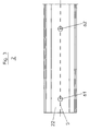
- the installation channel 2 is shown so that the inside 22 of the bottom 21 is visible.
- a height crack marking 5 is shown, which runs parallel to the longitudinal axis of the channel profile 2 and which in this exemplary embodiment is identical to the central axis of the channel profile 2.
- FIG. 4 shows the view of the cover 3 of the installation duct 1 according to the invention.
- a scale 4 is applied on the inside 31 of the cover 3, which runs parallel to the longitudinal axis of the cover 3 and has a non-metric division.
- the scale 4 is applied exactly on the central axis of the cover 3.
Landscapes
- Engineering & Computer Science (AREA)
- General Engineering & Computer Science (AREA)
- Mechanical Engineering (AREA)
- Architecture (AREA)
- Civil Engineering (AREA)
- Structural Engineering (AREA)
- Details Of Indoor Wiring (AREA)
Abstract
Description
So wird in der DE 297 03 480 U1 ein Installationskanal beschrieben, der aus polymerem Werkstoff hergestellt und als Klappkanal ausgeführt ist. Dieser Klappkanal soll bei einfachem Aufbau erhöhte mechanische Stabilität im Gebrauchszustand aufweisen.
Hier wird vorgeschlagen, den Installationskanal so auszubilden, daß das Kanalprofil aus mindestens zwei Teilprofilen aufgebaut ist, von denen jedes eine Seitenwand sowie je ein Teilstück der Rückwand und der Vorderwand aufweist. Dadurch soll es möglich sein, lediglich wenige Standardteilprofile herzustellen und auf Lager zu halten und dann, je nach Bedarf, aus diesen Teilprofilen die gewünschte Kanalform zusammenzusetzen.
Er ist aus einem einstückigen, in der Art eines C-profilierten Blechprofil hergestellt und soll ein vereinfachtes Einsetzen und elektrisch leitendes Kontaktieren einer Trennwand ermöglichen.
Ein weiterer Nachteil derartiger Installationskanäle wird darin gesehen, daß bei einer bereits an der Wand gekennzeichneten Höhenlinie diese nicht mit dem zu befestigenden Installationskanal in Zusammenhang gebracht werden kann.
Durch die symmetrische Einteilung ist die Verwendung eines zusätzlichen Meßmittels wie beispielsweise eines Zollstockes oder eines Bandmaßes überflüssig. Besonders vorteilhaft wirkt sich eine derartige metrische Skalierung auf dem Kanalprofil und/oder dem Deckel aus, wenn die zu befestigenden Teilstücke der Installationskanäle Längen von mehr als 2 m aufweisen, so daß hier mit einem Bandmaß gearbeitet werden muß, welches für eine exakte Bemessung der abzulängenden Installationskanäle einen zusätzlichen Installateur benötigt, was wiederum die Kosten für eine derartige Montage in die Höhe treibt.
In weiteren Ausführungsformen kann die Skalierung und/oder die Höhenrißmarkierung auch aufgeklebt bzw. eingeprägt sein, wobei andere Kennzeichnungsverfahren aus dem bekannten Stand der Technik nicht weiter benannt werden sollen.
- Figur 1:
- eine Schnittdarstellung durch einen herkömmlichen Installationskanal,
- Figur 2:
- eine Ansicht der Unterseite eines erfindungsgemäßen Installationskanals,
- Figur 3:
- eine Draufsicht auf ein Kanalprofil des erfindungsgemäßen Installationskanals,
- Figur 4:
- eine Ansicht des Deckels des erfindungsgemäßen Installationskanals.
Das Kanalprofil 2 besteht aus einem Boden 21 und diesem Ausführungsbeispiel an den rechtwinklig daran befindlichen Seitenwänden 23, 24. Der Deckel 3 weist eine Außenseite 32 und eine Innenfläche 31 auf, wobei der Deckel 3 mit seinen Randbereichen 33, 34 das an einer Seite offene Kanalprofil 2 umgreift und somit verschließt.
Im Bereich der oberen Kante 211 des Boden 21 des Kanalprofils 2 ist eine Skalierung 4 aufgebracht, welche eine metrische Einteilung aufweist und die mit 0 beginnend vom äußeren Rand des Bodens 21 des Kanalprofiles 2 aufgebracht ist. Durch diese metrische Skalierung ist ein Ablängen des erfindungsgemäßen Installationskanals 1 problemlos möglich, wobei zusätzlich noch der Abstand der Öffnungen 61, 62, welche in diesem Ausführungsbeispiel versetzt zur Mittelline des Kanalprofils 2 eingebracht sind, ablesbar sind. Auf der nicht sichtbaren Innenseite 22 des Boden 21 des Kanalprofils 2 sind Höhenrißmarkierungen 5 eingebracht, welche parallel zur Längsachse des Kanalprofils 2 verlaufen und durch die Mittelpunkte der jeweiligen Öffnungen 61, 62 längsverlaufend aufgebracht sind.
Auf der Innenseite 22 des Bodens 21 des Kanalprofils 2 ist eine Höhenrißmarkierung 5 dargestellt, welche parallel zur Längsachse des Kanalprofiles 2 verläuft und die in diesem Ausführungsbeispiel mit der Mittelachse des Kanalprofils 2 ident ist. Diese erweist sich als vorteilhaft, da die Öffnungen 61, 62 für das Einbringen der Befestigungsmittel des Installationskanals 1 in der gleichen Achse liegen und somit eine bereits angezeichnete Höhenlinie an der Wand oder der Decke mit der Höhenrißlinie 5 in Einklang gebracht werden kann und die Punkte für die Befestigungen durch die Öffnungen 61, 62 kennzeichenbar sind.
In diesem Ausführungsbeispiel ist auf der Innenseite 31 des Deckels 3 eine Skalierung 4 aufgebracht, welche parallel zur Längsachse des Deckels 3 verläuft und eine nicht metrische Einteilung aufweist. Bei diesem Ausführungsbeispiel ist die Skalierung 4 genau auf der Mittelachse des Deckels 3 aufgebracht.
Claims (8)
- Installationskanal, insbesondere Wandkanal mit einem zu einer Seite offenen Kanalprofil zur Aufnahme von elektrischen Installationseinrichtungen, Kabeln, Fluid-Leitungen und dergleichen und/oder einem Deckel
dadurch gekennzeichnet, daß auf wenigstens einer Seite (21, 22, 23, 24) des Kanalprofils (2) und/oder wenigstens einer Seite (31, 32) des Deckels (3) längsverlaufend wenigstens eine Skalierung (4) und/oder eine Höhenrißmarkierung (5) aufgebracht ist. - Installationskanal nach Anspruch 1, dadurch gekennzeichnet, daß die Skalierung (4) und/oder die Höhenrißmarkierung (5) parallel zur Längsachse des Kanalprofils (2) und/ oder des Deckels (3) verläuft.
- Installationskanal nach einem der vorhergehenden Ansprüche, dadurch gekennzeichnet, daß die Skalierung (4) eine metrische Einteilung aufweist.
- Installationskanal nach einem der vorhergehenden Ansprüche, dadurch gekennzeichnet, daß die Skalierung (4) eine nicht metrische Einteilung aufweist.
- Installationskanal nach einem der vorhergehenden Ansprüche, dadurch gekennzeichnet, daß die Höhenrißmarkierung (5) auf der Mittelachse des Kanalprofils (2) und/oder des Deckels (3) aufgebracht ist.
- Installationskanal nach einem der vorhergehenden Ansprüche, dadurch gekennzeichnet, daß die Skalierung (4) und/oder die Höhenrißmarkierung (5) auf das Kanalprofil (2) und/oder den Deckel (3) aufgedruckt ist.
- Installationskanal nach einem der vorhergehenden Ansprüche, dadurch gekennzeichnet, daß die Skalierung (4) und/oder die Höhenrißmarkierung (5) auf das Kanalprofil (2) und/oder den Deckel (3) aufgeklebt ist.
- Installationskanal nach einem der vorhergehenden Ansprüche, dadurch gekennzeichnet, daß die Skalierung (4) und/oder die Höhenrißmarkierung (5) auf das Kanalprofil (2) und/oder den Deckel (3) eingeprägt ist.
Applications Claiming Priority (2)
| Application Number | Priority Date | Filing Date | Title |
|---|---|---|---|
| DE20004923U DE20004923U1 (de) | 2000-06-23 | 2000-06-23 | Installationskanal |
| DE20004923U | 2000-06-23 |
Publications (2)
| Publication Number | Publication Date |
|---|---|
| EP1174971A2 true EP1174971A2 (de) | 2002-01-23 |
| EP1174971A3 EP1174971A3 (de) | 2003-08-13 |
Family
ID=7938889
Family Applications (1)
| Application Number | Title | Priority Date | Filing Date |
|---|---|---|---|
| EP01108680A Withdrawn EP1174971A3 (de) | 2000-06-23 | 2001-04-06 | Installationskanal |
Country Status (2)
| Country | Link |
|---|---|
| EP (1) | EP1174971A3 (de) |
| DE (1) | DE20004923U1 (de) |
Cited By (1)
| Publication number | Priority date | Publication date | Assignee | Title |
|---|---|---|---|---|
| GB2573098A (en) * | 2018-04-16 | 2019-10-30 | David Smith Benjamin | Trunking |
Families Citing this family (1)
| Publication number | Priority date | Publication date | Assignee | Title |
|---|---|---|---|---|
| ES1234984Y (es) * | 2019-07-31 | 2019-12-13 | Unex Aparellaje Electrico Sl | Conjunto para formar una canal para cables |
Family Cites Families (6)
| Publication number | Priority date | Publication date | Assignee | Title |
|---|---|---|---|---|
| DE7013979U (de) | 1970-04-16 | 1970-07-16 | Felten & Guilleaume Kabelwerk | Elektrisches kabel mit laengenmessband. |
| FR2290063A1 (fr) * | 1974-10-28 | 1976-05-28 | Pons Roger | Goulotte pour cablages, notamment electriques ou electroniques, et procede de reperage |
| JP2634940B2 (ja) * | 1990-09-25 | 1997-07-30 | 松下電工株式会社 | 配線用ダクト |
| DE19524381C2 (de) | 1995-07-04 | 1998-06-10 | Ackermann Albert Gmbh Co | Installationskanal mit einem zu einer Seite offenen metallischen Kanalprofil |
| DE29703480U1 (de) | 1997-02-26 | 1998-07-02 | Nowa-Plast GmbH Elektrotechnische Fabrik, 35799 Merenberg | Klappkanal |
| DE19709195C2 (de) | 1997-03-06 | 2001-09-06 | Ackermann Albert Gmbh Co | Elektroinstallationskanal |
-
2000
- 2000-06-23 DE DE20004923U patent/DE20004923U1/de not_active Expired - Lifetime
-
2001
- 2001-04-06 EP EP01108680A patent/EP1174971A3/de not_active Withdrawn
Cited By (1)
| Publication number | Priority date | Publication date | Assignee | Title |
|---|---|---|---|---|
| GB2573098A (en) * | 2018-04-16 | 2019-10-30 | David Smith Benjamin | Trunking |
Also Published As
| Publication number | Publication date |
|---|---|
| DE20004923U1 (de) | 2000-12-14 |
| EP1174971A3 (de) | 2003-08-13 |
Similar Documents
| Publication | Publication Date | Title |
|---|---|---|
| DE202013102583U1 (de) | Tür-Anordnung | |
| DE202013101469U1 (de) | Duschtür-Baugruppe | |
| EP0446875A2 (de) | Schutzgehäuse fÀ¼r optische Geräte | |
| DE2742111A1 (de) | Anzeigeinstrument, insbesondere fuer fahrzeuge | |
| DE3113679A1 (de) | Installationsgeraetedose zum einbau in installationskanaele | |
| DE2745278A1 (de) | Einsetzdose fuer elektrische installationen | |
| DE202015005671U1 (de) | Kupplungskopf | |
| DE20004923U1 (de) | Installationskanal | |
| DE202015005670U1 (de) | Kupplungskopf | |
| DE3242864C1 (de) | Elektromaschinengehäuse mit axial ausgerichteten Längskühlrippen und zwischen Längskühlrippen angeordneten Fußleisten | |
| DE19532392A1 (de) | Kabelkanalprofil zur Verlegung von Installationsleitungen oder dergleichen | |
| DE19523994C2 (de) | Anreißschablone für Elektroinstallationsdosen | |
| DE102018118772B4 (de) | Stecknusshalterahmenbaugruppe | |
| DE3023974A1 (de) | Profilschiene zum aufhaengen von geraeten | |
| EP3825505A1 (de) | Rollladenkasten mit einer stirnhaube | |
| DE102017114129B4 (de) | Montageplattenanordnung für den Innenausbau eines Schaltschranks und ein entsprechender Schaltschrank | |
| DE10239692B4 (de) | Verfahren zum Bestimmen von Befestigungspunkten sowie eine Vorrichtung zur Durchführung des Verfahrens | |
| DE10116322C2 (de) | Verbindungselement für Profilleisten sowie daraus hergestellte Rahmenanordnung für den Trockenbau | |
| DE2818336C3 (de) | Verbindung zwischen zwei Maschinenelementen | |
| DE20104472U1 (de) | Befestigungsvorrichtung für Revisionsrahmen | |
| DE102018133623A1 (de) | Adapter zur Positionierung und Befestigung eines Installationsgehäuses | |
| DE102014007863A1 (de) | Halteeinrichtung für einen Querträger in einem elektrischen Schaltschrank und Schaltschrank mit einer solchen Einrichtung | |
| DE29905482U1 (de) | Vorrichtung zur Bestimmung der lagerichtigen Position von genormten Schalter-/Steckdoseneinsätzen in zugeordneten Unterputz-Schalterdosen | |
| DE69110222T2 (de) | Modulares Befestigungsgehäuse für elektrisches Gerät. | |
| DE2432961B2 (de) | Beschlag fuer tueren zur befestigung eines lagerstuecks |
Legal Events
| Date | Code | Title | Description |
|---|---|---|---|
| PUAI | Public reference made under article 153(3) epc to a published international application that has entered the european phase |
Free format text: ORIGINAL CODE: 0009012 |
|
| AK | Designated contracting states |
Kind code of ref document: A2 Designated state(s): AT BE CH CY DE DK ES FI FR GB GR IE IT LI LU MC NL PT SE TR |
|
| AX | Request for extension of the european patent |
Free format text: AL;LT;LV;MK;RO;SI |
|
| PUAL | Search report despatched |
Free format text: ORIGINAL CODE: 0009013 |
|
| AK | Designated contracting states |
Designated state(s): AT BE CH CY DE DK ES FI FR GB GR IE IT LI LU MC NL PT SE TR |
|
| AX | Request for extension of the european patent |
Extension state: AL LT LV MK RO SI |
|
| STAA | Information on the status of an ep patent application or granted ep patent |
Free format text: STATUS: THE APPLICATION IS DEEMED TO BE WITHDRAWN |
|
| AKX | Designation fees paid | ||
| 18D | Application deemed to be withdrawn |
Effective date: 20031101 |
|
| REG | Reference to a national code |
Ref country code: DE Ref legal event code: 8566 |