EP1174570A1 - Einsteckschloss mit interner Kupplung - Google Patents
Einsteckschloss mit interner Kupplung Download PDFInfo
- Publication number
- EP1174570A1 EP1174570A1 EP01306247A EP01306247A EP1174570A1 EP 1174570 A1 EP1174570 A1 EP 1174570A1 EP 01306247 A EP01306247 A EP 01306247A EP 01306247 A EP01306247 A EP 01306247A EP 1174570 A1 EP1174570 A1 EP 1174570A1
- Authority
- EP
- European Patent Office
- Prior art keywords
- latch
- lockset
- retraction
- lock
- injector
- Prior art date
- Legal status (The legal status is an assumption and is not a legal conclusion. Google has not performed a legal analysis and makes no representation as to the accuracy of the status listed.)
- Granted
Links
Images


Classifications
-
- E—FIXED CONSTRUCTIONS
- E05—LOCKS; KEYS; WINDOW OR DOOR FITTINGS; SAFES
- E05B—LOCKS; ACCESSORIES THEREFOR; HANDCUFFS
- E05B63/00—Locks or fastenings with special structural characteristics
- E05B63/08—Mortise locks
-
- E—FIXED CONSTRUCTIONS
- E05—LOCKS; KEYS; WINDOW OR DOOR FITTINGS; SAFES
- E05B—LOCKS; ACCESSORIES THEREFOR; HANDCUFFS
- E05B47/00—Operating or controlling locks or other fastening devices by electric or magnetic means
- E05B47/06—Controlling mechanically-operated bolts by electro-magnetically-operated detents
- E05B47/0676—Controlling mechanically-operated bolts by electro-magnetically-operated detents by disconnecting the handle
- E05B47/0684—Controlling mechanically-operated bolts by electro-magnetically-operated detents by disconnecting the handle radially
- E05B47/0692—Controlling mechanically-operated bolts by electro-magnetically-operated detents by disconnecting the handle radially with a rectilinearly moveable coupling element
-
- E—FIXED CONSTRUCTIONS
- E05—LOCKS; KEYS; WINDOW OR DOOR FITTINGS; SAFES
- E05B—LOCKS; ACCESSORIES THEREFOR; HANDCUFFS
- E05B63/00—Locks or fastenings with special structural characteristics
- E05B63/18—Locks or fastenings with special structural characteristics with arrangements independent of the locking mechanism for retaining the bolt or latch in the retracted position
- E05B63/20—Locks or fastenings with special structural characteristics with arrangements independent of the locking mechanism for retaining the bolt or latch in the retracted position released automatically when the wing is closed
-
- E—FIXED CONSTRUCTIONS
- E05—LOCKS; KEYS; WINDOW OR DOOR FITTINGS; SAFES
- E05B—LOCKS; ACCESSORIES THEREFOR; HANDCUFFS
- E05B15/00—Other details of locks; Parts for engagement by bolts of fastening devices
- E05B15/04—Spring arrangements in locks
- E05B2015/0448—Units of springs; Two or more springs working together
-
- E—FIXED CONSTRUCTIONS
- E05—LOCKS; KEYS; WINDOW OR DOOR FITTINGS; SAFES
- E05B—LOCKS; ACCESSORIES THEREFOR; HANDCUFFS
- E05B15/00—Other details of locks; Parts for engagement by bolts of fastening devices
- E05B15/10—Bolts of locks or night latches
- E05B15/102—Bolts having movable elements
- E05B2015/105—Two pivoting latch elements with opposite inclined surfaces mounted on one slidable main latch-piece
-
- E—FIXED CONSTRUCTIONS
- E05—LOCKS; KEYS; WINDOW OR DOOR FITTINGS; SAFES
- E05B—LOCKS; ACCESSORIES THEREFOR; HANDCUFFS
- E05B47/00—Operating or controlling locks or other fastening devices by electric or magnetic means
- E05B47/0001—Operating or controlling locks or other fastening devices by electric or magnetic means with electric actuators; Constructional features thereof
- E05B2047/0014—Constructional features of actuators or power transmissions therefor
- E05B2047/0015—Output elements of actuators
- E05B2047/0016—Output elements of actuators with linearly reciprocating motion
-
- E—FIXED CONSTRUCTIONS
- E05—LOCKS; KEYS; WINDOW OR DOOR FITTINGS; SAFES
- E05B—LOCKS; ACCESSORIES THEREFOR; HANDCUFFS
- E05B47/00—Operating or controlling locks or other fastening devices by electric or magnetic means
- E05B47/0001—Operating or controlling locks or other fastening devices by electric or magnetic means with electric actuators; Constructional features thereof
- E05B2047/0014—Constructional features of actuators or power transmissions therefor
- E05B2047/0018—Details of actuator transmissions
- E05B2047/0026—Clutches, couplings or braking arrangements
- E05B2047/0031—Clutches, couplings or braking arrangements of the elastic type
-
- E—FIXED CONSTRUCTIONS
- E05—LOCKS; KEYS; WINDOW OR DOOR FITTINGS; SAFES
- E05B—LOCKS; ACCESSORIES THEREFOR; HANDCUFFS
- E05B47/00—Operating or controlling locks or other fastening devices by electric or magnetic means
- E05B47/0001—Operating or controlling locks or other fastening devices by electric or magnetic means with electric actuators; Constructional features thereof
- E05B47/0012—Operating or controlling locks or other fastening devices by electric or magnetic means with electric actuators; Constructional features thereof with rotary electromotors
-
- E—FIXED CONSTRUCTIONS
- E05—LOCKS; KEYS; WINDOW OR DOOR FITTINGS; SAFES
- E05B—LOCKS; ACCESSORIES THEREFOR; HANDCUFFS
- E05B55/00—Locks in which a sliding latch is used also as a locking bolt
-
- E—FIXED CONSTRUCTIONS
- E05—LOCKS; KEYS; WINDOW OR DOOR FITTINGS; SAFES
- E05B—LOCKS; ACCESSORIES THEREFOR; HANDCUFFS
- E05B63/00—Locks or fastenings with special structural characteristics
- E05B63/0065—Operating modes; Transformable to different operating modes
-
- Y—GENERAL TAGGING OF NEW TECHNOLOGICAL DEVELOPMENTS; GENERAL TAGGING OF CROSS-SECTIONAL TECHNOLOGIES SPANNING OVER SEVERAL SECTIONS OF THE IPC; TECHNICAL SUBJECTS COVERED BY FORMER USPC CROSS-REFERENCE ART COLLECTIONS [XRACs] AND DIGESTS
- Y10—TECHNICAL SUBJECTS COVERED BY FORMER USPC
- Y10T—TECHNICAL SUBJECTS COVERED BY FORMER US CLASSIFICATION
- Y10T292/00—Closure fasteners
- Y10T292/08—Bolts
- Y10T292/096—Sliding
- Y10T292/0969—Spring projected
- Y10T292/097—Operating means
-
- Y—GENERAL TAGGING OF NEW TECHNOLOGICAL DEVELOPMENTS; GENERAL TAGGING OF CROSS-SECTIONAL TECHNOLOGIES SPANNING OVER SEVERAL SECTIONS OF THE IPC; TECHNICAL SUBJECTS COVERED BY FORMER USPC CROSS-REFERENCE ART COLLECTIONS [XRACs] AND DIGESTS
- Y10—TECHNICAL SUBJECTS COVERED BY FORMER USPC
- Y10T—TECHNICAL SUBJECTS COVERED BY FORMER US CLASSIFICATION
- Y10T292/00—Closure fasteners
- Y10T292/08—Bolts
- Y10T292/096—Sliding
- Y10T292/1014—Operating means
- Y10T292/1021—Motor
-
- Y—GENERAL TAGGING OF NEW TECHNOLOGICAL DEVELOPMENTS; GENERAL TAGGING OF CROSS-SECTIONAL TECHNOLOGIES SPANNING OVER SEVERAL SECTIONS OF THE IPC; TECHNICAL SUBJECTS COVERED BY FORMER USPC CROSS-REFERENCE ART COLLECTIONS [XRACs] AND DIGESTS
- Y10—TECHNICAL SUBJECTS COVERED BY FORMER USPC
- Y10T—TECHNICAL SUBJECTS COVERED BY FORMER US CLASSIFICATION
- Y10T70/00—Locks
- Y10T70/50—Special application
- Y10T70/5093—For closures
- Y10T70/5155—Door
- Y10T70/5199—Swinging door
- Y10T70/5226—Combined dead bolt and latching bolt
- Y10T70/5239—Dead bolt, dogged latch bolt
-
- Y—GENERAL TAGGING OF NEW TECHNOLOGICAL DEVELOPMENTS; GENERAL TAGGING OF CROSS-SECTIONAL TECHNOLOGIES SPANNING OVER SEVERAL SECTIONS OF THE IPC; TECHNICAL SUBJECTS COVERED BY FORMER USPC CROSS-REFERENCE ART COLLECTIONS [XRACs] AND DIGESTS
- Y10—TECHNICAL SUBJECTS COVERED BY FORMER USPC
- Y10T—TECHNICAL SUBJECTS COVERED BY FORMER US CLASSIFICATION
- Y10T70/00—Locks
- Y10T70/50—Special application
- Y10T70/5093—For closures
- Y10T70/5155—Door
- Y10T70/5199—Swinging door
- Y10T70/5246—Dead bolts
- Y10T70/5296—Single
- Y10T70/5319—Sliding
- Y10T70/5341—Key operable only
-
- Y—GENERAL TAGGING OF NEW TECHNOLOGICAL DEVELOPMENTS; GENERAL TAGGING OF CROSS-SECTIONAL TECHNOLOGIES SPANNING OVER SEVERAL SECTIONS OF THE IPC; TECHNICAL SUBJECTS COVERED BY FORMER USPC CROSS-REFERENCE ART COLLECTIONS [XRACs] AND DIGESTS
- Y10—TECHNICAL SUBJECTS COVERED BY FORMER USPC
- Y10T—TECHNICAL SUBJECTS COVERED BY FORMER US CLASSIFICATION
- Y10T70/00—Locks
- Y10T70/50—Special application
- Y10T70/5093—For closures
- Y10T70/5155—Door
- Y10T70/5199—Swinging door
- Y10T70/5372—Locking latch bolts, biased
- Y10T70/5385—Spring projected
- Y10T70/5389—Manually operable
- Y10T70/5394—Directly acting dog for exterior, manual, bolt manipulator
- Y10T70/5416—Exterior manipulator declutched from bolt when dogged
-
- Y—GENERAL TAGGING OF NEW TECHNOLOGICAL DEVELOPMENTS; GENERAL TAGGING OF CROSS-SECTIONAL TECHNOLOGIES SPANNING OVER SEVERAL SECTIONS OF THE IPC; TECHNICAL SUBJECTS COVERED BY FORMER USPC CROSS-REFERENCE ART COLLECTIONS [XRACs] AND DIGESTS
- Y10—TECHNICAL SUBJECTS COVERED BY FORMER USPC
- Y10T—TECHNICAL SUBJECTS COVERED BY FORMER US CLASSIFICATION
- Y10T70/00—Locks
- Y10T70/70—Operating mechanism
- Y10T70/7051—Using a powered device [e.g., motor]
- Y10T70/7062—Electrical type [e.g., solenoid]
- Y10T70/7113—Projected and retracted electrically
Definitions
- This invention relates generally to locksets employed to secure doors and electro-mechanical assemblies that permit locksets to be electrically locked and unlocked. More particularly, the present invention relates generally to a mortise-type lockset that incorporates an internal selectively engageable electro-mechanical clutch assembly.
- Locksets that incorporate a lockable latch and/or dead bolt have long been incorporated into doors.
- Electronic security systems for controlling access through doors are also common.
- Electronic security systems typically control access through doors incorporating mechanical locksets by selectively engaging the rotatable operator (usually a lever or knob) on the unsecured or outside side of the door. This has been accomplished by means of an electro-mechanical clutch mounted between the operator and the lockset.
- a properly activated clutch mechanically couples the operator to the lockset and permits rotation of the operator to retract the latch and allow entry through the door.
- Locksets used to control access through frequently used doors typically incorporate a beveled latch and a spring for biasing the latch in the projected or latched position.
- Such self-latching locksets have the advantage of automatically latching the door when it is closed, and with certain lock mechanisms, automatically locking the door.
- the beveled, spring biased latches employed in self-latching locksets have the disadvantage of being susceptible to tampering that may result in unauthorized entry. In many installations, tools or other slim objects can be slipped between the door and the doorframe to engage the beveled edge of the latch and force the latch into a retracted position, thereby allowing the door to be opened.
- Dead bolts have been employed to overcome some of these deficiencies. Dead bolts typically have a squared off end which is not susceptible to tampering. Dead bolts also typically have a longer throw and are not spring biased, therefore maintaining the dead bolt in an extended position until the lock mechanism is employed to retract it. A major deficiency of dead bolts is that they must typically be manually engaged. Manual engagement is inconvenient for a door that is frequently used.
- the present invention provides a lockset comprising:
- the present invention provides a lockset for mounting in a mortise of a door having a secured side and an unsecured side, said lockset comprising:
- a preferred embodiment of the mortise lockset with internal clutch includes a self-latching autobolt and an electrically actuated coupling that permits retraction of the autobolt by the operator on the unsecured side of the door.
- a key actuation mechanism preferably allows the lockset to be operated as a conventional key-based security system or operated in conjunction with an electronic security system.
- the autobolt or self-latching dead bolt is spring biased toward a projected or latched position.
- a retraction lever is engaged with the autobolt and is pivotable by a key operated retraction cam or rotational movement produced by operators (levers or knobs) located on the secured and unsecured side of the door. Pivoting of the retraction lever overcomes the spring bias, resulting in retraction of the autobolt.
- Operators on the secured and unsecured sides of the door are connected to inside and outside cams in the lockset, respectively, for rotation therewith.
- the inside cam located adjacent the secured side (inside) of the door, is continuously coupled to the retraction lever, allowing rotation of the operator to pivot the retraction lever and retract the autobolt.
- the outside cam located adjacent the unsecured side (outside) of the door, is selectively coupled with the retraction lever.
- the inside and outside cams are positioned on either side of the retraction lever at the retraction lever pivot point.
- the inside cam, outside cam and retraction lever share a common axis of rotation.
- entry from the unsecured side of the door may be obtained either by actuating the electro-mechanical coupling between the outside cam and the retraction lever, or using a key to rotate the retraction cam.
- the electrically actuated coupling incorporates a motor which, by moving an injector and an injector arm, exerts force on a locking piece, resulting in rotational engagement of the outside cam to the retraction lever.
- the locking piece is movably secured for rotation with the retraction lever by a pin and is spring biased toward a locked position in which the locking piece is disengaged from the outside cam.
- a convex head on the pin is slidably engaged along an arcuate surface of the pivotable injector arm.
- the injector arm is disposed between the pinhead and an axially movable injector.
- a rounded corner of the injector slidably engages a ramp on the injector arm, whereby the injector arm can be moved toward the clutch assembly by the injector.
- a coil spring drive shaft connects the injector to the motor such that rotation of the drive shaft moves the injector along an axis.
- rotation of the drive shaft in a first direction moves the rounded corner of the injector along the ramp of the injector arm, pivoting the injector arm to overcome the spring bias on the locking piece and force the locking piece into an unlocked position.
- the locking piece In an unlocked position, the locking piece is engaged with the outside cam.
- Rotation of the drive shaft in a second direction moves the rounded corner of the injector in the opposite direction along the ramp of the injector arm, allowing the injector arm to be moved away from the clutch assembly by the spring bias on the locking piece.
- a locked position is achieved when the locking piece is disengaged from the outside cam.
- the outside cam rotates independently of the retraction lever and rotation of the operator located on the unsecured side of the door will not retract the latch.
- An autobolt assembly in accordance with one embodiment of the present invention includes a roller captured within a squared-off projectable end of the bolt.
- the roller is positioned so that a portion of the roller protrudes from the outer end face of the bolt.
- a projectable bi-beveled auxiliary latch and associated pivotable hook restrain the bolt in a retracted position in which only the roller protrudes from the latch edge of the door.
- the auxiliary latch is spring biased toward a projected position in which the auxiliary latch acts to pivot the hook into engagement with a notch in the bolt, restraining the bolt in the retracted position.
- a closing door causes the auxiliary latch to be forced into a retracted position in which the auxiliary latch acts to pivot the hook away from engagement with the bolt, releasing the bolt from its retracted position.
- the spring biased bolt moves toward a projected position causing the roller in the end face of the bolt to contact the strike plate.
- the roller rotates freely, allowing the bolt to move over the strike plate until the bolt is aligned with the latch opening in the strike plate, at which time the bolt projects fully into a latched position in the latch opening.
- Retracting the bolt and opening the door allows the auxiliary latch to re-assume its projected position, causing the hook to restrain the bolt in a retracted position until the door closes, thereby bringing the auxiliary latch into contact with the strike plate once again.
- the bolt is locked in the projected position, ensuring that only the retraction lever can retract the bolt.
- a pivoting lock bar is spring biased toward a position in which the lock bar engages the rear or inner end of the projected bolt to prevent the bolt from being moved to the retracted position.
- the lock bar has a cam surface, which cooperates with a protrusion on the retraction lever. Movement of the retraction lever to retract the bolt also moves the lock bar to a position where the lock bar does not interfere with retraction of the bolt.
- the lock bar prevents potential unauthorized entry by maintaining the latch bolt in the projected position despite the presence of a countering force applied by a tool or other object.
- the lock bar is inaccessible to a burglar and can be disengaged only by movement of the retraction lever.
- a further alternative embodiment combines the electrically actuated clutch assembly with a more conventional self-latching mortise lockset.
- An object of the present invention is to provide a new and improved lockset that incorporates an internal electrically actuated clutch mechanism.
- Another object of the present invention is to provide a new and improved lockset that is self-latching but includes the security advantages of a dead bolt.
- a further object of the present invention is to provide a new and improved lockset that may be incorporated into either a standard key-based access control system or an electronic access control system.
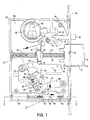
- a first embodiment of the mortise lockset in accordance with the present invention is generally designated by the numeral 10.
- the mortise lockset 10 is mountable in the mortise of a door and is adapted to engage the strike of a doorframe (see Figure 13). Latch operators on the secured (inside) of a door and the unsecured (outside) of a door connect to the lockset 10 via cams 81, 80 for operation of the lockset.
- the mortise lockset 10 is equipped with both key and electro-mechanical locking assemblies, allowing the mortise lockset 10 to be operated as a conventional keyed lockset or be incorporated into an electronic access control system.
- the mortise lockset comprises a substantially rectangular lock case 100 that includes an integral backing plate 104.
- the case 100 provides a mounting surface for the components as well as protective housing and a support for mounting the mortise lockset 10 in the mortise of a door.
- the face plate 102 is flush with the latch edge of the door and disposed in opposing parallel relationship to the strike of the door frame when the door is closed (see Figure 13).
- the Figures illustrate the mortise lockset 10 with the front plate 106 of the lock case 100 removed, so the internal components are easily viewed. With the exception of the bolt 12 and auxiliary bolt 40, all the components of the mortise lockset, including the clutch mechanism, the key override, the lock bar and the electrical clutch actuation components are contained within the case 100.
- the case 100 provides pivot points for some components, such as the lock bar 50, the bolt hook 42 and the injector arm 88.
- FIGS 2 and 5 illustrate a sectional view through the clutch assembly and show the components mounted for rotation between the backing plate 104 and the front plate 106.
- Other components such as the auxiliary bolt 40, are provided with tabs 51 that are configured to slide within slots 49 in the backing plate 104 and the front plate 106.
- Still further components, such as the throw rod stop 26 are fixedly mounted between the backing plate 104 and the front plate 106 (best seen in Figure 11).
- the mortise lockset may be installed in a rectangular mortise typical of any conventional mortise lockset.
- the bolt 12 is preferably a generally rectangular member having a short beveled perimeter at the projected or outer end 14.
- the outer end 14 further includes a recessed roller 16.
- the bolt may be threaded to the throw rod 20 or secured by a setscrew 24 that is received in a recess of the rod.
- a spring 28 engages the inner end 15 of the bolt 12 and is secured at the opposing end against a stop 26.
- the stop 26 is fixedly mounted between a front plate, not illustrated, and the backing plate 104 of the case 100 to provide support for the slidably received throw rod 20.
- the spring 28 functions to bias the bolt 12 toward an extended or latched position as illustrated in Figures 1, 4, and 10.
- the latch of a self-latching lockset typically has a beveled outer end.
- the beveled surface of the latch engages the strike of the door frame and is forced back into the lockset until the door reaches a position in which the latch can project into the latch opening in the strike.
- a mortise lockset in accordance with at least preferred embodiments, achieves self-latching convenience without need for a large beveled surface on the latch or the typically short latch throw of prior art self-latching locksets.
- the outer end 14 of the bolt 12 has a short bevel extending less than 1/5 of the length of the projected length of the bolt.
- Figure 13 illustrates a portion of a doorframe 72 including a strike 75.
- the strike typically incorporates an outer lip 74 that extends beyond the doorframe 72 and is curved or bent to form a camming surface which will engage protruding parts of the lockset as the door swings closed.
- the strike includes a latch opening 76 for receiving the latch and/or bolt.
- FIG. 8 illustrates the position of the internal components of the mortise lockset 10 corresponding to a door that has been opened and is now swinging closed.
- the bolt is illustrated in a retracted position where only the outer tip 14 of the bolt and its recessed roller 1'6 project from the face plate 102.
- a bi-beveled auxiliary latch 40 projects from the face plate 102.
- the auxiliary latch pivots a hook 42 via a pin 46 that is slidably positioned in a curved slot 47 within the hook.
- the hook 42 is mounted to pivot on pivot point 44.
- the auxiliary latch 40 is biased toward an extended position by spring 48.
- the faceplate 102 of the lockset 10 When the door is opened, the faceplate 102 of the lockset 10 is moved away from the strike of the doorframe, allowing the auxiliary latch 40 to assume its projected position (as illustrated in Figure 8).
- the pin 46 carried by the auxiliary latch 40 acts within the curved slot 47 of the hook 42 to pivot the hook into engagement with a notch 18 on the side of the bolt 12.
- the bolt 12 is thus held in a retracted position (see Figures 8 and 9) even after the latch operator is released.
- a closing door brings the latch edge of the door, including the face plate 102 of the lockset and its protruding parts (the auxiliary latch 40 and the outer end 14 of the bolt 12), into an opposing parallel relationship with the door frame 72 and the strike 75.
- the bi-beveled tip of the auxiliary latch 40 encounters the strike 75 at location 78.
- the curved outer lip 74 of the strike 75 interacts with the beveled surface of the auxiliary strike 40 to urge the auxiliary bolt into a retracted position as illustrated in Figure 9.
- the recessed roller 16 in the outer end 14 of the bolt 12 also encounters the curved lip 74 of the strike 75. Engagement of the roller 16 against the strike 75 at location 79 relieves some pressure from the hooked engagement between the latch 12 and the hook 42. Inward movement of the auxiliary latch 40 causes pin 46 to move in slot 47 of the hook 42, pivoting the hook away from its engagement with the notch 18 in the bolt 12. As pictured in Figure 9, the bolt 12 is now outwardly biased by spring 28, disengaged from the hook 42 and engaged with the strike at area 79.
- the slightly beveled configuration of the outer end 14 of the bolt 12 and the recessed roller 16 permit smooth sliding engagement between the lip 74 of the strike 75 and the bolt 12.
- Figure 10 illustrates the positions of the auxiliary latch 40, hook 42 and bolt 12 in a closed and latched door.
- the shape and extended projection of the bolt 12 are very similar to those of a deadbolt.
- the squared shape and extended projection provide a strong connection between the door and the doorframe.
- the squared bolt resists tampering by not presenting a beveled surface that can be manipulated by a thin tool in the manner applied to a typical self-latching lockset.
- a retraction lever 30 is mechanically connected to the throw rod 20 so that pivotal movement of the retraction lever 30 in the direction of arrow A will overcome the bias of the spring 28 and retract the bolt 12.
- the retraction lever is pivotable by a key operable retraction cam 62 or rotational movement produced by operators (levers or knobs) located on the secured and unsecured sides of the door.
- the mortise lockset 10 pictured in Figures 1, 4, and 7 is viewed from the unsecured (outside) of the door. Operators on the secured (inside) and unsecured (outside) sides of the door are connected to an inside cam 81 and an outside cam 80 in the lockset, respectively, for providing rotational movement to the cams.
- Figure 2 illustrates a cross-sectional view through the backing plate 104, the inside cam 81, the pivot end of the retraction lever 30, the outside cam 80 and the front plate 106.
- Figure 2 also presents a cross-sectional view of the components of the selective mechanical coupling between the outside cam 80 and the retraction lever 30.
- a z-shaped locking piece 82 is movably connected to the retraction lever by an engagement pin 83.
- the locking piece 82 is captured between a convex head 84 of the engagement pin 83 and surfaces of the inside cam 81 and outside cam 80.
- the engagement pin 83 is slidably captured in a guide in the retraction lever 30. This arrangement permits the locking piece 82 to move along an axis generally orthogonal to the axis of rotation shared by the inside cam 81, outside cam 80, and retraction lever 30.
- the inside cam 81 and the outside cam 80 are mirror images of each other.
- Each cam 80, 81 is provided with a face 110 for engagement with the locking piece 82 and a lobe 112.
- the coupling arrangement is configured so that the locking piece 82 is continually engaged with a face 110 of the inside cam 81. This engagement transmits rotational force applied to the inside cam 81 to pivot retraction lever 30, retract the bolt and open the door, thus allowing free egress from the area secured by the door.
- FIG. 2 illustrates the components of the coupling in a locked position.
- the locking pin 83 and locking piece 82 are permitted to move away from the common axis of rotation shared by the inside cam 81, outside cam 80 and retraction lever 30. Such movement disengages the locking piece from the face 110 of the outside cam 80.
- the outside cam 80 rotates independently of the retraction lever 30. Accordingly, rotational movement applied to the outside cam 80 by an operator on the unsecured side of the door will not retract the bolt and open the door.
- the locking piece 82 is configured so that 180° rotation of the locking piece about the engagement pin 83 reverses the secured and unsecured sides of the door.
- a 180° rotation of the locking piece will reconfigure the clutch mechanism for continuous engagement between the locking piece 82 and the outside cam 80 while permitting selective engagement between the inside cam 81 and the locking piece 82.
- the inside cam is now configured to control egress while the outside cam permits unregulated entry. In this manner, the mortise lockset may be easily configured to suit the particular application.
- the mechanical coupling just described is preferably electrically actuated via a motor 90 that rotates a drive shaft 96, producing linear movement in an injector 92.
- a pivotable injector arm 88 is engaged between the convex head 84 of the engagement pin 83 and a rounded corner 93 of the injector 92.
- the injector arm 88 is a passive member and is pivoted by forces exerted on it by the head 84 of the injector pin 83 and the rounded corner 93 of the injector 92.
- the locking piece 82 and engagement pin 83 are biased toward a locked position by spring 86.
- the injector 92 is coupled to the coil drive shaft 96 by a drive pin 94.
- the injector 92 is in the form of a block.
- Drive pin 94 is carried by the injector 92 and engaged between coils of the drive shaft 96. Rotational movement of the drive shaft 96 produces lateral movement of the injector 92. Lateral movement of the injector 92 away from the mechanical coupling ( Figure 1, arrow C) permits the spring biased locking piece 82 and engagement pin 83 to pivot the injector arm 88 away from the coupling ( Figure 1, arrow B).
- Figures 1-3 illustrate the relative positions of the coupling and coupling drive components in the mortise lockset 10 corresponding to a locked condition.
- injector 92 and injector arm 88 are positioned to permit the locking piece 82 and engagement pin 83 to move away from the axis of the coupling to a position where the locking piece 82 is no longer engaged with the outside cam 80 (see Figure 2)
- Figures 4-6 illustrate the relative positions of the coupling and coupling drive components in the mortise lockset 10 corresponding to an unlocked condition.
- the motor 90 rotates drive shaft 96 so that drive pin 94 is drawn toward the coupling ( Figure 4, arrow D). Movement of the drive pin 94 and associated injector 92 cause the rounded corner 93 of the injector to engage the ramp 87 on the injector arm 88, pivoting the injector arm toward the coupling ( Figure 4, arrow E). Pivoting of the injector arm 88 overcomes the spring bias on the locking piece 82 and engagement pin 83, moving the locking piece into engagement with the outside cam 80 (see Figure 5). When spring 86 is compressed, the locking piece is moved into engagement with both the inside and outside cams 81, 80.
- the injector arm 88 is provided with an arcuate engagement surface 89 configured to maintain the compressed condition of spring 86 and the engaged position of the locking piece 82 throughout the pivotal movement of the retraction lever.
- the retraction lever is equipped with a return bias spring 32 that returns the retraction lever and associated coupling components to their preactuation positions as illustrated in Figure 4.
- the coil spring drive shaft 96 has the capability to store energy applied to the injector 92 by the motor 90. Under certain circumstances, the locking piece may be obstructed from achieving the unlocked position illustrated in Figure 4. If, for example, the outside operator is held down, the outside cam is rotated counter-clockwise into a position which blocks movement of the locking piece toward the unlocked position. As a result of the blockage, energy applied by the motor 90 to move the injector 92, injector arm 88, engagement pin 83 and locking piece 82 will not result in movement of these components. However, the motor 90 will rotate the coil spring drive shaft 96 whether the injector moves or not.
- the drive shaft 96 is compressed beyond the drive pin 94 and stretched between the drive pin and the motor 90 by energy applied to the injector 92 by the motor.
- the outside cam returns to its normal position, freeing the locking piece 82, engagement pin 83, injector arm 88 and injector 92 to achieve their unlocked positions.
- the energy stored in the stretched and compressed portions of the drive shaft 96 is now able to move the components to their unlocked positions.
- the mortise lockset 10 incorporates a further security feature comprising a lock bar 50.
- the lock bar 50 is biased by spring 52 toward a lock position in which the free end 56 of the lock bar is positioned to block retraction of the projected bolt 12.
- the lock bar 50 is moved from the lock position by a guide pin 31 on the retraction lever 30. Pivoting the retraction lever 30 to retract the bolt 12 engages the guide pin 31 on the retraction lever with a cam surface 54 on the lock bar 50. Movement of the retraction lever 30 causes a corresponding pivot of the lock bar 50 away from its locked position.
- the lock bar being internal to the mortise lockset 10, is inaccessible to a potential burglar. Effectively, the lock bar 50 may be moved from the locked position only by a corresponding movement of the retraction lever 30.
- the novel configuration and features of the mortise lockset 10, including the squared bolt 12, the extended projection of the bolt, the autobolt system and lock bar 50 effectively combine the security features of a deadbolt with the convenience of a self-latching lockset.
- the mortise lockset 10 may also be operated as a conventional keyed access control system.
- the mortise lockset 10 is equipped with a key cylinder 60 and a retraction cam 62.
- a properly cut key inserted in key cylinder 60 permits rotation of the retraction cam 62.
- Rotation of the retraction cam 62 brings cam lobe 63 into engagement with the end of the retraction lever 30.
- Movement of the retraction lever 30 induced by interaction with the retraction cam 62 is the same pivoting movement produced by the latch operators via the electro-mechanical coupling previously described.
- the mortise lockset in accordance with at least preferred embodiments incorporates features making it compatible with both keyed and electronic access control systems.
- the key cylinder 60 and retraction cam 62 may provide the primary access control or may be used as a key override feature. Incorporating electrically actuated access control features into a mortise lockset that is also equipped for key operation simplifies installation of an access control system by permitting key access control until a suitable electronic system may be installed. Further, the separately installed clutch mechanisms known in the prior art are no longer needed.
- the electric power necessary to operate the motor 90 may be provided by a battery pack (not illustrated) or from a power supply.
- a battery powered mortise lockset may also be remotely actuated by radio, infra red or some similar signal.
- the signals necessary to actuate the motor 90 may also be transmitted by conductors (not illustrated) positioned within the door. While these arrangements are not illustrated, it is well known in the art to provide remote actuation of electrically operable assemblies. Any human operated or automated access control system may be used to actuate the clutch mechanism.
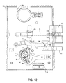
- FIG. 11 is a perspective view of an alternative embodiment 10a of a mortise lockset incorporating the electrically actuated internal clutch, key access control capability and lock bar features in accordance with an embodiment of the invention.
- the alternative embodiment 10a also incorporates a more conventional self-latching configuration.
- a latch 13 with a large angled arcuate surface is spring biased toward an extended, latched position (spring not shown). The latch 13 is positioned to engage the strike of a doorframe.
- the force of the closing door moves the latch 13 into a retracted position until the latch is aligned with a latch opening in the strike. Once aligned with the strike opening, the latch 13 projects to a latched position. Because the latch operator on the unsecured side of the door is selectively engaged with the retraction lever 30, the latched door is automatically locked.
- the alternative embodiment 10a is equipped with a modified form of the lock bar security feature.
- the free end 56 of the lock bar 50 is coupled to an alternative auxiliary bolt 41 by a pin 58.
- the lock bar is biased toward a lock position in which the lock bar blocks retraction of the latch 13.
- the lock bar 50 must be moved from the lock position to permit the door to be opened and again to permit the door to close and latch.
- the lock bar control surface 54 and retraction lever mounted guide pin 31 cooperate to move the lock bar from the lock position when the door is being opened.
- pivoting of the retraction lever 30 moves the lock bar 50 and also retracts the latch 13.
- the lock bar 50 must be restrained from achieving a lock position so that the latch will be permitted to retract upon encountering the strike as the door closes.
- a control surface 59 on the auxiliary latch 41 acts on guide pin 58 to restrain the lock bar from achieving the lock position.
- the closing door engages the latch 13 and bi-beveled auxiliary latch 41 against the strike 75 of the doorframe 72 at areas 79 and 78a respectively, urging both the latch and auxiliary latch into a retracted position.
- the control surface 59 of the auxiliary latch 41 permits the lock bar to pivot to the lock position.
- the self-latching latch 13 of the alternative embodiment 10a incorporates tamper resistant features typical of a dead bolt.
- the mortise lockset 10a illustrated in Figures 11 and 12 may be used to explain some features consistent with embodiments of the invention not found in the mortise lockset 10 of Figures 1-10.
- the mortise lockset 10a of Figures 11 and 12 is illustrated from the secured or inside of the door. From this side, the cam facing the viewer is the inside cam 80.
- the inside cam 80 is continuously coupled to the retraction lever 30 by the engagement of cam lobe 112 with a projection 111 from the retraction lever 30. Rotational motion applied to the inside cam 80 is directly transmitted to pivot the retraction lever 30 which moves the lock bar from the locked position and retracts the latch 13.
- a Z-shaped locking piece is positioned to engage the inside cam 81 continuously and selectively engage the outside cam 80.
- the mortise lockset 10a provides the projection 111 to continuously engage the inside cam 81.
- the locking piece 82' is L-shaped, a protruding part of the L selectively engageable with the outside cam 81.
- Figures 11 and 12 illustrate the coupling components of the mortise lockset 10a in a locked condition.
- the injector 92, injector arm 88, engagement pin 83, and locking piece 82' are positioned so that the extension of the locking piece is not engaged with the outside cam 81.
- the coupling components are so positioned the operator and outside cam 81 are in a free wheel state relative to the retraction lever 30 and rotational motion applied to the operator on the unsecured side of the door will not unlock the door.
- the mortise lockset 10a functions in the same manner as the mortise lockset 10. It should be noted that the mortise lockset 10a incorporates the same key actuation and electrically actuated coupling as described in the mortise lockset 10. It should also be noted that the mortise lockset 10a incorporates the lock bar feature, adding security to the convenience of a self-latching lockset.
Landscapes
- Engineering & Computer Science (AREA)
- Structural Engineering (AREA)
- Lock And Its Accessories (AREA)
Applications Claiming Priority (2)
| Application Number | Priority Date | Filing Date | Title |
|---|---|---|---|
| US621197 | 1975-10-09 | ||
| US09/621,197 US6354121B1 (en) | 2000-07-21 | 2000-07-21 | Mortise lockset with internal clutch |
Publications (2)
| Publication Number | Publication Date |
|---|---|
| EP1174570A1 true EP1174570A1 (de) | 2002-01-23 |
| EP1174570B1 EP1174570B1 (de) | 2007-03-21 |
Family
ID=24489153
Family Applications (1)
| Application Number | Title | Priority Date | Filing Date |
|---|---|---|---|
| EP01306247A Expired - Lifetime EP1174570B1 (de) | 2000-07-21 | 2001-07-20 | Schloss mit interner Kupplung |
Country Status (3)
| Country | Link |
|---|---|
| US (1) | US6354121B1 (de) |
| EP (1) | EP1174570B1 (de) |
| DE (1) | DE60127350T2 (de) |
Cited By (19)
| Publication number | Priority date | Publication date | Assignee | Title |
|---|---|---|---|---|
| WO2002059440A1 (en) * | 2001-01-24 | 2002-08-01 | Abloy Oy | Installation arrangement for controlling handle operation in a door lock and a door lock provided with an installation arrangement of this kind |
| NL1020047C2 (nl) * | 2002-02-22 | 2003-08-25 | Lips Nederland B V | Slotsamenstel. |
| FR2884272A1 (fr) * | 2005-04-11 | 2006-10-13 | Dubois Ind Sa Sa | Serrure a embrayage |
| WO2007021182A2 (en) * | 2005-08-17 | 2007-02-22 | Lips Nederland B.V. | Lock case with divided follower |
| EP1777361A2 (de) | 2005-10-24 | 2007-04-25 | Sitech-Sicherheitstechnik GmbH | Schloss, insbesondere Einstemmschloss |
| WO2007100167A1 (en) * | 2006-02-28 | 2007-09-07 | Gab-Sik Kim | Hub-locking apparatus for mortise lock assembly |
| EP1881135A1 (de) * | 2006-06-26 | 2008-01-23 | Salto Systems, S.L. | Kupplungsmechanismus zur Ankopplung an Türschlösser mit Verschlussriegel mittels Griffen oder Knöpfen |
| EP1990487A2 (de) * | 2007-05-11 | 2008-11-12 | Grundmann Beschlagtechnik GmbH | Türschloss |
| EP1842989A3 (de) * | 2006-04-03 | 2008-11-19 | Hewi Heinrich Wilke Gmbh | Einsteckschloss |
| WO2009113022A1 (en) * | 2008-03-11 | 2009-09-17 | Piotr Leonard Kowalczyk | Lock |
| AU2005254927B2 (en) * | 2004-06-22 | 2010-01-21 | Assa Ab | A device for mechanical guiding, a lock module and a lock device comprising such a device |
| WO2011103844A1 (de) * | 2010-02-26 | 2011-09-01 | ASTRA Gesellschaft für Asset Management mbH & Co. KG | Elektronisches einsteckschloss |
| GB2456214B (en) * | 2008-01-10 | 2012-08-08 | Assa Abloy Ltd | Lock assembly |
| CN104314366A (zh) * | 2014-08-21 | 2015-01-28 | 成都迅德科技有限公司 | 锁具结构 |
| EP2860331A1 (de) * | 2013-10-08 | 2015-04-15 | Assa Ab | Griffvorrichtung |
| CN105464482A (zh) * | 2016-01-22 | 2016-04-06 | 南京东屋电气有限公司 | 卡板锁 |
| EP2597233A3 (de) * | 2011-11-24 | 2016-09-21 | ASTRA Gesellschaft für Asset Management mbH & Co. KG | Selbstverriegelndes Fallenschloss |
| FR3045091A1 (fr) * | 2015-12-11 | 2017-06-16 | Dubois Ind | Serrure actionnable par une premiere commande telle qu'une barre anti-panique et par une deuxieme commande a cle |
| WO2023198949A1 (es) * | 2022-04-13 | 2023-10-19 | Salto Systems, S.L. | Sistema de seguridad para cerraduras |
Families Citing this family (65)
| Publication number | Priority date | Publication date | Assignee | Title |
|---|---|---|---|---|
| US20040089033A1 (en) * | 1998-10-29 | 2004-05-13 | Mei-Feng Lu | Door lock structure |
| EP1266111B1 (de) * | 2000-03-24 | 2004-09-22 | Azoteq (PTY) Limited | Schloss |
| US6714118B1 (en) | 2000-05-08 | 2004-03-30 | Harrow Products, Inc. | Modular electronic door security system |
| AUPQ757600A0 (en) * | 2000-05-18 | 2000-06-08 | Keightley, Kym John | Dual locking mechanism |
| AU2002953027A0 (en) * | 2002-11-29 | 2002-12-19 | Inovec Pty Ltd I | A lock slider body |
| US6622535B2 (en) * | 2000-10-13 | 2003-09-23 | Tung Lung Metal Industry Co., Ltd. | Lock construction having an electrically activated clutch mechanism and a transmission mechanism |
| GB0110456D0 (en) * | 2001-04-28 | 2001-06-20 | Meritor Light Vehicle Sys Ltd | Latch assembly |
| AUPR620901A0 (en) * | 2001-07-06 | 2001-08-02 | Harkins, Peter William | Latch assembly |
| US6619705B2 (en) | 2002-01-04 | 2003-09-16 | Schlage Lock Company | Mortise lockset with internal clutch |
| US6869116B2 (en) | 2003-02-13 | 2005-03-22 | Schlage Lock Company | Lockset with external clutching assembly |
| US7096698B2 (en) * | 2003-03-11 | 2006-08-29 | Harrow Products Llc | Override assembly for door lock systems having a clutch mechanism |
| US7246827B2 (en) * | 2004-03-30 | 2007-07-24 | Security Door Controls | Fail safe/fail secure lock with quick change access window |
| US20050217324A1 (en) * | 2004-04-06 | 2005-10-06 | Royal Lock Corporation | Lock with a linear movement hook resulting from rotatable movement of a control knob |
| US8353189B2 (en) * | 2006-01-09 | 2013-01-15 | Schlage Lock Company | Manual override mechanism for electromechanical locks |
| US7377140B2 (en) * | 2006-04-25 | 2008-05-27 | I-Tek Metal Mfg. Co., Ltd. | Lock with clutching function |
| WO2008056948A1 (en) * | 2006-11-09 | 2008-05-15 | Techsumer Co.Ltd. | Door lock device |
| US7866192B2 (en) * | 2007-03-07 | 2011-01-11 | Angelo Gianelo | Locking mechanism for use with a drawer |
| WO2008153707A2 (en) * | 2007-05-21 | 2008-12-18 | Truth Hardware Corporation | Multipoint lock mechanism |
| US7533551B1 (en) * | 2008-03-03 | 2009-05-19 | Ming-I Liu | Door lock with key cylinder |
| US20090229321A1 (en) * | 2008-03-05 | 2009-09-17 | Telezygology, Inc. | Lock Assembly |
| US7849719B2 (en) * | 2008-03-28 | 2010-12-14 | Der-Yuh Chern | Locking device |
| DE102008016698B4 (de) * | 2008-03-31 | 2021-03-04 | Dormakaba Deutschland Gmbh | Schloss mit einem Selektorelement zur Umstellung der Funktionseigenschaften des Schlosses |
| CA2681067C (en) * | 2008-10-03 | 2015-04-14 | Truth Hardware Corporation | Sliding door multipoint mortise lock with shoot bolts |
| US20100109416A1 (en) * | 2008-11-03 | 2010-05-06 | Jones Margaret L | Adjustable safety harness |
| DE102009006352B4 (de) * | 2009-01-28 | 2011-02-17 | G. Schwepper Beschlag Gmbh + Co | Lock-Box |
| US7634927B1 (en) * | 2009-02-04 | 2009-12-22 | I-Tek Metal Mfg. Co., Ltd. | Panic exit door lock allowing locking on both sides |
| US9217264B2 (en) | 2009-02-20 | 2015-12-22 | Utc Fire & Security Corporation | Low energy clutch for electronic door lock |
| US8141400B2 (en) * | 2009-04-10 | 2012-03-27 | Emtek Products, Inc. | Keypad lockset |
| US8292336B2 (en) * | 2009-04-15 | 2012-10-23 | Townsteel, Inc. | Mortise lock assembly |
| CA2708912C (en) | 2009-06-30 | 2013-02-19 | Truth Hardware Corporation | Multi-point mortise lock mechanism for swinging door |
| US8162358B2 (en) * | 2009-07-10 | 2012-04-24 | Thase Enterprise Co., Ltd. | Lock device |
| US8079238B2 (en) * | 2010-02-23 | 2011-12-20 | Thase Enterprise Co., Ltd. | Lock device |
| PL2441905T3 (pl) * | 2010-10-12 | 2014-07-31 | Frinova Gmbh | Zamek |
| US20120139267A1 (en) * | 2010-12-06 | 2012-06-07 | Te-Yu Chen | Cushion structure of lock |
| US8590948B2 (en) * | 2011-01-12 | 2013-11-26 | I-Tek Metal Mfg. Co., Ltd | Outer operational device for panic exit door lock |
| DE102011116049A1 (de) * | 2011-10-17 | 2013-04-18 | Hochschule Niederrhein | Einsteckschloss für eine Tür |
| DE102012001787A1 (de) * | 2012-01-31 | 2013-08-01 | Assa Abloy Sicherheitstechnik Gmbh | Türöffner und Tür mit Türöffner |
| US8641104B1 (en) * | 2013-01-16 | 2014-02-04 | I-Tek Metal Mfg. Co., Ltd. | Latch device with a clutch function |
| US9422742B2 (en) | 2013-04-09 | 2016-08-23 | Keith Pardoe | Systems, devices, and/or methods for managing swinging doors |
| DE102014104793B4 (de) * | 2014-04-03 | 2015-11-05 | Dom-Sicherheitstechnik Gmbh & Co. Kg | Kupplungsanordnung für Schließzylinder mit Lauffeder |
| CA2895036C (en) | 2014-06-20 | 2022-09-20 | Truth Hardware Corporation | Recessed lock actuating device for sliding doors |
| US9850685B2 (en) * | 2014-09-03 | 2017-12-26 | Schlage Lock Company Llc | Lock drive assemblies |
| US9787127B2 (en) * | 2014-12-05 | 2017-10-10 | I-Tek Metal Mfg. Co., Ltd | Door lock with a wireless charging device |
| US9631399B1 (en) * | 2015-11-03 | 2017-04-25 | Digilock Asia Ltd. | Miniaturized electronic cam lock |
| US9803395B2 (en) * | 2015-11-17 | 2017-10-31 | Te-Yu Chen | Lock structure suitable for various lock cores |
| US20170268256A1 (en) * | 2016-03-21 | 2017-09-21 | 1 Adolfo, Llc | Electric lock with latch retractor |
| DE102016107717A1 (de) * | 2016-04-26 | 2017-10-26 | Maco Technologie Gmbh | Türschloss |
| US11111698B2 (en) | 2016-12-05 | 2021-09-07 | Endura Products, Llc | Multipoint lock |
| US10876324B2 (en) | 2017-01-19 | 2020-12-29 | Endura Products, Llc | Multipoint lock |
| ES2689376B1 (es) * | 2017-03-01 | 2019-08-21 | Salto Systems Sl | Cerradura de embutir de embrague reversible |
| WO2019018427A1 (en) | 2017-07-19 | 2019-01-24 | United States Postal Service | LOCK |
| US10890019B2 (en) * | 2017-10-24 | 2021-01-12 | Wfe Technology Corp. | Reversible electric door lock |
| US10907381B2 (en) * | 2018-06-19 | 2021-02-02 | Wfe Technology Corp. | Electronic door lock with a monitoring unit |
| US10738506B2 (en) | 2018-07-24 | 2020-08-11 | Schlage Lock Company Llc | Modular clutching mechanism |
| CN109025520B (zh) * | 2018-08-30 | 2024-04-05 | 四川宝家安锁业有限公司 | 一种手自一体内嵌式自动锁 |
| US10961746B2 (en) | 2018-09-20 | 2021-03-30 | Dormakaba Usa Inc. | Mortise lock and mortise lock systems and methods |
| SE543072C2 (en) * | 2018-10-23 | 2020-09-29 | Stendals El Ab | Locking device with first and second follower arrangement and locking arm with blocking part |
| US11136789B2 (en) | 2018-12-28 | 2021-10-05 | Accurate Lock & Hardware Co. Llc | Anti-ligature door hardware with enhanced safety features |
| US11851925B2 (en) * | 2019-02-27 | 2023-12-26 | Sargent Manufacturing Company | Key override for electromechanical multi-point latching device |
| US11746565B2 (en) | 2019-05-01 | 2023-09-05 | Endura Products, Llc | Multipoint lock assembly for a swinging door panel |
| US11952812B2 (en) * | 2019-06-20 | 2024-04-09 | Nikolaos Zafeirakis | Contact-minimizing door opening and closing system |
| US11933092B2 (en) | 2019-08-13 | 2024-03-19 | SimpliSafe, Inc. | Mounting assembly for door lock |
| CN113437430B (zh) * | 2020-03-04 | 2022-09-02 | 广东博智林机器人有限公司 | 一种锁定机构及电池仓 |
| TWM617032U (zh) * | 2021-06-01 | 2021-09-11 | 廖奕帆 | 電鎖 |
| ES2950158A1 (es) * | 2022-03-04 | 2023-10-05 | Salto Systems Sl | Sistema de seguridad para cerraduras |
Citations (6)
| Publication number | Priority date | Publication date | Assignee | Title |
|---|---|---|---|---|
| US4854619A (en) * | 1987-02-23 | 1989-08-08 | Ryobi Ltd. | Electric key |
| EP0537531A1 (de) * | 1991-10-16 | 1993-04-21 | BKS GmbH | Türschloss |
| GB2269418A (en) * | 1992-08-05 | 1994-02-09 | Pickersgill Kaye Ltd | Latch mechanism with reversable handedness |
| US5640863A (en) | 1995-09-06 | 1997-06-24 | Harrow Products, Inc. | Clutch mechanism for door lock system |
| US5953942A (en) * | 1996-11-26 | 1999-09-21 | Ilco Unican Inc. | Catch mechanism for locks |
| US6045169A (en) * | 1996-04-16 | 2000-04-04 | Harrow Products, Inc. | Latch bolt set |
Family Cites Families (3)
| Publication number | Priority date | Publication date | Assignee | Title |
|---|---|---|---|---|
| DE3835349A1 (de) * | 1988-10-17 | 1990-04-19 | Winkhaus Fa August | Schloss |
| JP3289249B2 (ja) * | 1992-11-27 | 2002-06-04 | 美和ロック株式会社 | 錠止装置 |
| US6145353A (en) * | 1999-02-02 | 2000-11-14 | Unican Electronics | Electronically activated door lock assembly |
-
2000
- 2000-07-21 US US09/621,197 patent/US6354121B1/en not_active Expired - Lifetime
-
2001
- 2001-07-20 DE DE60127350T patent/DE60127350T2/de not_active Expired - Lifetime
- 2001-07-20 EP EP01306247A patent/EP1174570B1/de not_active Expired - Lifetime
Patent Citations (6)
| Publication number | Priority date | Publication date | Assignee | Title |
|---|---|---|---|---|
| US4854619A (en) * | 1987-02-23 | 1989-08-08 | Ryobi Ltd. | Electric key |
| EP0537531A1 (de) * | 1991-10-16 | 1993-04-21 | BKS GmbH | Türschloss |
| GB2269418A (en) * | 1992-08-05 | 1994-02-09 | Pickersgill Kaye Ltd | Latch mechanism with reversable handedness |
| US5640863A (en) | 1995-09-06 | 1997-06-24 | Harrow Products, Inc. | Clutch mechanism for door lock system |
| US6045169A (en) * | 1996-04-16 | 2000-04-04 | Harrow Products, Inc. | Latch bolt set |
| US5953942A (en) * | 1996-11-26 | 1999-09-21 | Ilco Unican Inc. | Catch mechanism for locks |
Cited By (34)
| Publication number | Priority date | Publication date | Assignee | Title |
|---|---|---|---|---|
| US6978646B2 (en) | 2001-01-24 | 2005-12-27 | Abloy Oy | Installation arrangement for controlling handle operation in a door lock and a door lock provided with an installation arrangement of this kind |
| WO2002059440A1 (en) * | 2001-01-24 | 2002-08-01 | Abloy Oy | Installation arrangement for controlling handle operation in a door lock and a door lock provided with an installation arrangement of this kind |
| NL1020047C2 (nl) * | 2002-02-22 | 2003-08-25 | Lips Nederland B V | Slotsamenstel. |
| AU2005254927B2 (en) * | 2004-06-22 | 2010-01-21 | Assa Ab | A device for mechanical guiding, a lock module and a lock device comprising such a device |
| CN101014750B (zh) * | 2004-06-22 | 2011-07-27 | Assa有限公司 | 用于机械引导的装置、包括这种装置的锁模块和锁装置 |
| AU2005254927B9 (en) * | 2004-06-22 | 2010-06-03 | Assa Ab | A device for mechanical guiding, a lock module and a lock device comprising such a device |
| FR2884272A1 (fr) * | 2005-04-11 | 2006-10-13 | Dubois Ind Sa Sa | Serrure a embrayage |
| WO2007021182A2 (en) * | 2005-08-17 | 2007-02-22 | Lips Nederland B.V. | Lock case with divided follower |
| NL1029754C2 (nl) * | 2005-08-17 | 2007-03-05 | Lips Nederland B V | Slotkast met gedeelde tuimelaar. |
| WO2007021182A3 (en) * | 2005-08-17 | 2007-04-05 | Lips Nederland B V | Lock case with divided follower |
| EP1777361A2 (de) | 2005-10-24 | 2007-04-25 | Sitech-Sicherheitstechnik GmbH | Schloss, insbesondere Einstemmschloss |
| EP1777361A3 (de) * | 2005-10-24 | 2008-10-01 | Sitech-Sicherheitstechnik GmbH | Schloss, insbesondere Einstemmschloss |
| WO2007100167A1 (en) * | 2006-02-28 | 2007-09-07 | Gab-Sik Kim | Hub-locking apparatus for mortise lock assembly |
| EP1842989A3 (de) * | 2006-04-03 | 2008-11-19 | Hewi Heinrich Wilke Gmbh | Einsteckschloss |
| EP1881135A1 (de) * | 2006-06-26 | 2008-01-23 | Salto Systems, S.L. | Kupplungsmechanismus zur Ankopplung an Türschlösser mit Verschlussriegel mittels Griffen oder Knöpfen |
| ES2323201A1 (es) * | 2006-06-26 | 2009-07-08 | Salto Systems S.L. | Mecanismo de embrague acoplable a cerraduras de puertas con pestillo de cierre accionado por manillas o pomos. |
| EP1990487A2 (de) * | 2007-05-11 | 2008-11-12 | Grundmann Beschlagtechnik GmbH | Türschloss |
| EP1990487A3 (de) * | 2007-05-11 | 2011-03-09 | Grundmann Beschlagtechnik GmbH | Türschloss |
| GB2456214B (en) * | 2008-01-10 | 2012-08-08 | Assa Abloy Ltd | Lock assembly |
| GB2470701B (en) * | 2008-03-11 | 2012-12-26 | Piotr Leonard Kowalczyk | Lock |
| GB2470701A (en) * | 2008-03-11 | 2010-12-01 | Piotr Leonard Kowalczyk | Lock |
| US8316674B2 (en) | 2008-03-11 | 2012-11-27 | Piotr Leonard Kowalczyk | Lock |
| WO2009113022A1 (en) * | 2008-03-11 | 2009-09-17 | Piotr Leonard Kowalczyk | Lock |
| WO2011103844A1 (de) * | 2010-02-26 | 2011-09-01 | ASTRA Gesellschaft für Asset Management mbH & Co. KG | Elektronisches einsteckschloss |
| EP2597233A3 (de) * | 2011-11-24 | 2016-09-21 | ASTRA Gesellschaft für Asset Management mbH & Co. KG | Selbstverriegelndes Fallenschloss |
| WO2015052102A1 (en) * | 2013-10-08 | 2015-04-16 | Assa Ab | Handle device |
| EP2860331A1 (de) * | 2013-10-08 | 2015-04-15 | Assa Ab | Griffvorrichtung |
| US9850686B2 (en) | 2013-10-08 | 2017-12-26 | Assa Oem Ab | Handle device |
| EA031442B1 (ru) * | 2013-10-08 | 2019-01-31 | Асса Оем Аб | Узел дверной или оконной ручки |
| CN104314366A (zh) * | 2014-08-21 | 2015-01-28 | 成都迅德科技有限公司 | 锁具结构 |
| FR3045091A1 (fr) * | 2015-12-11 | 2017-06-16 | Dubois Ind | Serrure actionnable par une premiere commande telle qu'une barre anti-panique et par une deuxieme commande a cle |
| CN105464482A (zh) * | 2016-01-22 | 2016-04-06 | 南京东屋电气有限公司 | 卡板锁 |
| CN105464482B (zh) * | 2016-01-22 | 2017-07-21 | 南京东屋电气有限公司 | 卡板锁 |
| WO2023198949A1 (es) * | 2022-04-13 | 2023-10-19 | Salto Systems, S.L. | Sistema de seguridad para cerraduras |
Also Published As
| Publication number | Publication date |
|---|---|
| US6354121B1 (en) | 2002-03-12 |
| EP1174570B1 (de) | 2007-03-21 |
| DE60127350D1 (de) | 2007-05-03 |
| DE60127350T2 (de) | 2007-11-29 |
Similar Documents
| Publication | Publication Date | Title |
|---|---|---|
| US6354121B1 (en) | Mortise lockset with internal clutch | |
| US11414891B2 (en) | Door strike having a kicker and an adjustable dead latch release | |
| US7980603B2 (en) | Rotating latch for latching and unlatching a door | |
| US6389855B2 (en) | Locking device for a door, window or the like | |
| US5078436A (en) | Motor-vehicle door with antitheft override | |
| US6971686B2 (en) | Multipoint lock system | |
| US6416088B1 (en) | Power-operated motor-vehicle door latch with antitheft | |
| AU2010202495B2 (en) | Locks | |
| EP0115430A2 (de) | Türschloss | |
| US20230323705A1 (en) | Locking assembly with spring mechanism | |
| US6151935A (en) | Deadbolt combination lock system with automatic locking spring bolt | |
| JPS6278382A (ja) | ドア錠掛け装置 | |
| CN113167081A (zh) | 锁组件 | |
| US6007115A (en) | Door lock assembly | |
| US6299222B1 (en) | Latchbolt | |
| US4623175A (en) | High security door latch and deadbolt | |
| EP0976899B1 (de) | Automatisches Türschloss | |
| GB2307270A (en) | A lock mechanism | |
| US4711478A (en) | High security deadlocking door latch | |
| EP1113134A2 (de) | Schlossmechanismus | |
| AU2006100903B4 (en) | Locks | |
| GB2408773A (en) | Lock actuation mechanism comprising spring-loaded locking pin | |
| AU700951B2 (en) | Improvements in sliding bolt locks | |
| JP3576536B2 (ja) | 引き出し回転操作型扉用ロックハンドル装置 | |
| GB2408774A (en) | Lock actuation mechanism comprising latch spindle mounted in cruciform aperture |
Legal Events
| Date | Code | Title | Description |
|---|---|---|---|
| PUAI | Public reference made under article 153(3) epc to a published international application that has entered the european phase |
Free format text: ORIGINAL CODE: 0009012 |
|
| AK | Designated contracting states |
Kind code of ref document: A1 Designated state(s): DE FR GB Kind code of ref document: A1 Designated state(s): AT BE CH CY DE DK ES FI FR GB GR IE IT LI LU MC NL PT SE TR |
|
| AX | Request for extension of the european patent |
Free format text: AL;LT;LV;MK;RO;SI |
|
| 17P | Request for examination filed |
Effective date: 20020722 |
|
| AKX | Designation fees paid |
Free format text: DE FR GB |
|
| 17Q | First examination report despatched |
Effective date: 20030331 |
|
| RTI1 | Title (correction) |
Free format text: LOCKSET WITH INTERNAL CLUTCH |
|
| GRAP | Despatch of communication of intention to grant a patent |
Free format text: ORIGINAL CODE: EPIDOSNIGR1 |
|
| GRAS | Grant fee paid |
Free format text: ORIGINAL CODE: EPIDOSNIGR3 |
|
| GRAA | (expected) grant |
Free format text: ORIGINAL CODE: 0009210 |
|
| AK | Designated contracting states |
Kind code of ref document: B1 Designated state(s): DE FR GB |
|
| REG | Reference to a national code |
Ref country code: GB Ref legal event code: FG4D |
|
| REF | Corresponds to: |
Ref document number: 60127350 Country of ref document: DE Date of ref document: 20070503 Kind code of ref document: P |
|
| PLBE | No opposition filed within time limit |
Free format text: ORIGINAL CODE: 0009261 |
|
| STAA | Information on the status of an ep patent application or granted ep patent |
Free format text: STATUS: NO OPPOSITION FILED WITHIN TIME LIMIT |
|
| 26N | No opposition filed |
Effective date: 20071227 |
|
| REG | Reference to a national code |
Ref country code: FR Ref legal event code: PLFP Year of fee payment: 16 |
|
| REG | Reference to a national code |
Ref country code: FR Ref legal event code: PLFP Year of fee payment: 17 |
|
| REG | Reference to a national code |
Ref country code: FR Ref legal event code: PLFP Year of fee payment: 18 |
|
| PGFP | Annual fee paid to national office [announced via postgrant information from national office to epo] |
Ref country code: FR Payment date: 20190621 Year of fee payment: 19 |
|
| PGFP | Annual fee paid to national office [announced via postgrant information from national office to epo] |
Ref country code: GB Payment date: 20190624 Year of fee payment: 19 Ref country code: DE Payment date: 20190620 Year of fee payment: 19 |
|
| REG | Reference to a national code |
Ref country code: DE Ref legal event code: R119 Ref document number: 60127350 Country of ref document: DE |
|
| GBPC | Gb: european patent ceased through non-payment of renewal fee |
Effective date: 20200720 |
|
| PG25 | Lapsed in a contracting state [announced via postgrant information from national office to epo] |
Ref country code: FR Free format text: LAPSE BECAUSE OF NON-PAYMENT OF DUE FEES Effective date: 20200731 Ref country code: GB Free format text: LAPSE BECAUSE OF NON-PAYMENT OF DUE FEES Effective date: 20200720 |
|
| PG25 | Lapsed in a contracting state [announced via postgrant information from national office to epo] |
Ref country code: DE Free format text: LAPSE BECAUSE OF NON-PAYMENT OF DUE FEES Effective date: 20210202 |