EP1174229A2 - Längsteilschere - Google Patents
Längsteilschere Download PDFInfo
- Publication number
- EP1174229A2 EP1174229A2 EP01117274A EP01117274A EP1174229A2 EP 1174229 A2 EP1174229 A2 EP 1174229A2 EP 01117274 A EP01117274 A EP 01117274A EP 01117274 A EP01117274 A EP 01117274A EP 1174229 A2 EP1174229 A2 EP 1174229A2
- Authority
- EP
- European Patent Office
- Prior art keywords
- knife
- knives
- movable
- shaft
- slitting shear
- Prior art date
- Legal status (The legal status is an assumption and is not a legal conclusion. Google has not performed a legal analysis and makes no representation as to the accuracy of the status listed.)
- Withdrawn
Links
Images
Classifications
-
- B—PERFORMING OPERATIONS; TRANSPORTING
- B23—MACHINE TOOLS; METAL-WORKING NOT OTHERWISE PROVIDED FOR
- B23D—PLANING; SLOTTING; SHEARING; BROACHING; SAWING; FILING; SCRAPING; LIKE OPERATIONS FOR WORKING METAL BY REMOVING MATERIAL, NOT OTHERWISE PROVIDED FOR
- B23D35/00—Tools for shearing machines or shearing devices; Holders or chucks for shearing tools
- B23D35/008—Means for changing the cutting members
-
- B—PERFORMING OPERATIONS; TRANSPORTING
- B26—HAND CUTTING TOOLS; CUTTING; SEVERING
- B26D—CUTTING; DETAILS COMMON TO MACHINES FOR PERFORATING, PUNCHING, CUTTING-OUT, STAMPING-OUT OR SEVERING
- B26D5/00—Arrangements for operating and controlling machines or devices for cutting, cutting-out, stamping-out, punching, perforating, or severing by means other than cutting
- B26D5/02—Means for moving the cutting member into its operative position for cutting
- B26D5/04—Means for moving the cutting member into its operative position for cutting by fluid pressure
-
- B—PERFORMING OPERATIONS; TRANSPORTING
- B26—HAND CUTTING TOOLS; CUTTING; SEVERING
- B26D—CUTTING; DETAILS COMMON TO MACHINES FOR PERFORATING, PUNCHING, CUTTING-OUT, STAMPING-OUT OR SEVERING
- B26D7/00—Details of apparatus for cutting, cutting-out, stamping-out, punching, perforating, or severing by means other than cutting
- B26D7/26—Means for mounting or adjusting the cutting member; Means for adjusting the stroke of the cutting member
- B26D7/2628—Means for adjusting the position of the cutting member
- B26D7/2635—Means for adjusting the position of the cutting member for circular cutters
-
- B—PERFORMING OPERATIONS; TRANSPORTING
- B26—HAND CUTTING TOOLS; CUTTING; SEVERING
- B26D—CUTTING; DETAILS COMMON TO MACHINES FOR PERFORATING, PUNCHING, CUTTING-OUT, STAMPING-OUT OR SEVERING
- B26D7/00—Details of apparatus for cutting, cutting-out, stamping-out, punching, perforating, or severing by means other than cutting
- B26D7/26—Means for mounting or adjusting the cutting member; Means for adjusting the stroke of the cutting member
- B26D2007/2685—Means for mounting or adjusting the cutting member; Means for adjusting the stroke of the cutting member flexible mounting means
-
- Y—GENERAL TAGGING OF NEW TECHNOLOGICAL DEVELOPMENTS; GENERAL TAGGING OF CROSS-SECTIONAL TECHNOLOGIES SPANNING OVER SEVERAL SECTIONS OF THE IPC; TECHNICAL SUBJECTS COVERED BY FORMER USPC CROSS-REFERENCE ART COLLECTIONS [XRACs] AND DIGESTS
- Y10—TECHNICAL SUBJECTS COVERED BY FORMER USPC
- Y10T—TECHNICAL SUBJECTS COVERED BY FORMER US CLASSIFICATION
- Y10T83/00—Cutting
- Y10T83/768—Rotatable disc tool pair or tool and carrier
- Y10T83/7809—Tool pair comprises rotatable tools
- Y10T83/7822—Tool pair axially shiftable
- Y10T83/7826—With shifting mechanism for at least one element of tool pair
-
- Y—GENERAL TAGGING OF NEW TECHNOLOGICAL DEVELOPMENTS; GENERAL TAGGING OF CROSS-SECTIONAL TECHNOLOGIES SPANNING OVER SEVERAL SECTIONS OF THE IPC; TECHNICAL SUBJECTS COVERED BY FORMER USPC CROSS-REFERENCE ART COLLECTIONS [XRACs] AND DIGESTS
- Y10—TECHNICAL SUBJECTS COVERED BY FORMER USPC
- Y10T—TECHNICAL SUBJECTS COVERED BY FORMER US CLASSIFICATION
- Y10T83/00—Cutting
- Y10T83/768—Rotatable disc tool pair or tool and carrier
- Y10T83/7809—Tool pair comprises rotatable tools
- Y10T83/783—Tool pair comprises contacting overlapped discs
- Y10T83/7834—With means to effect axial pressure on pair
-
- Y—GENERAL TAGGING OF NEW TECHNOLOGICAL DEVELOPMENTS; GENERAL TAGGING OF CROSS-SECTIONAL TECHNOLOGIES SPANNING OVER SEVERAL SECTIONS OF THE IPC; TECHNICAL SUBJECTS COVERED BY FORMER USPC CROSS-REFERENCE ART COLLECTIONS [XRACs] AND DIGESTS
- Y10—TECHNICAL SUBJECTS COVERED BY FORMER USPC
- Y10T—TECHNICAL SUBJECTS COVERED BY FORMER US CLASSIFICATION
- Y10T83/00—Cutting
- Y10T83/768—Rotatable disc tool pair or tool and carrier
- Y10T83/7809—Tool pair comprises rotatable tools
- Y10T83/7847—Tool element axially shiftable
Definitions
- the invention relates to a slitting shear consisting from two relatively adjustable knife shafts, each are equipped with at least one knife.
- Machines of this type are used for cutting sheet material used.
- Usual slitting shears contain two stands supporting frame.
- the stands take the storage of two adjustable knife shafts that can be driven and at least one cooperative for the dividing process Wear pair of knives.
- One of the stands can be set up and converted opened on the machine.
- the invention has for its object a pair of scissors to create the type mentioned with which a constant Cutting quality can be guaranteed.
- a hydraulic or preferably pneumatic force for the movable knife or a knife holder holding the knife is provided.
- the Fluid system can be used to exert forces in both directions, e.g. be formed by positive and negative pressure.
- the Hydraulics allow fine tuning of the knife acting force and thus ensures the desired division or cutting process.
- a machine tool created an automatic employment of the Tools, especially knives or spring knives.
- the reliable installation of the knife pairs will provide the machine in particular at a tool exchange simplified and accelerated.
- a simple solution in terms of production technology is the use a mechanical pressure medium, e.g. a compression spring, for the opening direction of the knife and a print medium, e.g. Compressed air, as a force in the opposite direction.
- a mechanical pressure medium e.g. a compression spring
- a print medium e.g. Compressed air
- the compression spring holds the movable knife holder in one open position. After one operation and switching off The medium pressure can therefore be changed immediately by the machine opened and after the retrofit the adjustment of the knife shaft be done without risk. The creation of the Finally, the knife is carried out automatically by initiating the Medium pressure.
- the design according to the invention can be used with all slitting shears and apply regardless of the knives used.
- spring knives can be used for the movable knives used on a movable knife holder be attached.
- Knife shafts each equipped with two or more knives, at least some of the knives or their knife carriers are mobile.
- the one knife shaft is fixed and the other knife shaft with movable knives or knife carriers stocked.
- the Knife shaft with the movable knives or knife carriers too fixed knife. This means that the effort is negligible Loss of division quality reduced.
- the fixed knife this Wave the less worn fixed knives of the other wave be compared.
- Knife shaft for the movable knife or a tool set on the Knife shaft is axially displaceable. With that all knives with the same pressure on the associated counter knife pressed, which is due to different Wear and tear differences resulting from the spring knife be balanced.
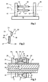
- a slitting shear 10 which is essentially consists of a frame 11 on which a fixed Stand 12 and a slidable stand 13 are mounted.
- Two drivable cutter shafts 14 and 15 are in the stands 12 and 13 stored.
- the knife shafts 14, 15 are opened after the slidable or swingable stand 13 with knives 16.17 for the cutting process.
- 1 is a Knife pair 16.17 shown.
- the shaft axes are with identified by the reference numerals 18, 19.
- the pair of knives 16, 17 from FIG. 1 is shown in more detail in FIG.
- the knife 17 located on the knife shaft 15 with the Cutting edge 20 is fixed to the shaft 15.
- the knife 16 of the other knife shaft 14 consists of a spring knife 21 and a knife holder 22 holding this, which in the direction of Shaft axis 18 is designed to be displaceable.
- the movable knife 16 is after employment of the movable Knife shaft 14 by means of one acting in the direction of arrow 23 Force shifted so that the spring knife 21 with its cutting edge to bear against the cutting edge 20 of the fixed knife 17 comes. Due to the persistent force acts on the cutting edges of the pair of knives always have the same clamping force, so that a qualitatively uniform division of the cutting goods is guaranteed.
- Knife shafts 14, 15 are usually used to cut several webs Knife shafts 14, 15 with a corresponding number of knife pairs 16, 17 equipped.
- Each movable knife 16 is individually with pressurized. As a rule, one becomes Knife shaft, e.g. 14, with movable and the other knife shaft 15 equipped with fixed knives.
- FIG. 1 An example of this variant is shown in FIG the upper knife shaft 14 from Figure 1 with two knives in longitudinal section is shown.
- a fixed knife 30 is movable Knife 31 separated by a spacer ring 32.
- another spacer ring 33 separates the movable one Knife 31 from a second fixed knife, not shown, etc.
- the tools of both knife shafts become hydraulic locked.
- the fixed knives 30 each consist of a knife holder 34, which is anchored between spacer rings 32 and a spring knife 35 wears.
- the movable knives 31 each contain a knife carrier 37 which axially in on a fixed base 36 Arrow direction 23 'is movable.
- the knife carrier 37 is from a compression spring 38 in the open position.
- the Compression spring 38 or another mechanical pressure element or an elastic material holds the movable knife in its place open position.
- the movable ones Knife carrier 37 After turning the knife shafts 14, 15, the movable ones Knife carrier 37 with a clamping force against the force of the Spring 38 acted upon.
- the spring knife 21 are against the fixed knife 17 of the other knife shaft 15 placed.
- With a corresponding design of the clamping force is a machine tool created an automatic adjustment of the tools, especially knives or spring knives. Except the resulting simplification and acceleration of the When using the machine, the knives remain even if they are long-lasting Cutting processes in plant.
- a channel system is located in the cutter shaft 14 for the pressure medium provided that in an inner bore 39 and a longitudinal groove 40 exists.
Landscapes
- Engineering & Computer Science (AREA)
- Mechanical Engineering (AREA)
- Life Sciences & Earth Sciences (AREA)
- Forests & Forestry (AREA)
- Physics & Mathematics (AREA)
- Fluid Mechanics (AREA)
- Details Of Cutting Devices (AREA)
- Nonmetal Cutting Devices (AREA)
- Shearing Machines (AREA)
Abstract
Description
Claims (10)
- Längsteilschere bestehend aus zwei relativ zueinander verstellbaren Messerwellen, die jeweils mit mindestens einem Messer ausgerüstet sind, dadurch gekennzeichnet, daß mindestens ein Messer (16,31) parallel (23,23') zur Messerwellenachse (18,19) verstellbar ist.
- Längsteilschere nach Anspruch 1, dadurch gekennzeichnet, daß Mittel (38,39-42) zur Ausübung von Kräften in die Verstellrichtung (23,23') des bzw. der Messer (16,31) vorgesehen sind.
- Längsteilschere nach Anspruch 2, dadurch gekennzeichnet, daß auf das bzw. die beweglichen Messer (16) ein hydraulisches oder pneumatisches System wirkt.
- Längsteilschere nach Anspruch 2, dadurch gekennzeichnet, daß auf das bzw. die beweglichen Messer jeweils eine mechanische Druckkraft (38,23') und in Gegenrichtung (23') ein Druckmedium (39-42) wirken.
- Längsteilschere nach Anspruch 3 oder 4, dadurch gekennzeichnet, daß in der Messerwelle (14) für bewegliche Messer (16,31) Bohrungen (39) und ggf. mindestens eine Längsnut (40) für das Hydrauliksystem vorgesehen sind.
- Längsteilschere nach einem der vorhergehenden Ansprüche, dadurch gekennzeichnet, daß das oder die beweglichen Messer (16,31) aus einem beweglichen Messerträger (22,37) und einem daran befestigten Federmesser (21) ausgebildet ist.
- Längsteilschere nach einem der vorhergehenden Ansprüche, dadurch gekennzeichnet, daß die Messerwellen (14,15) jeweils mit zwei oder mehr Messern (30,31;17) ausgerüstet sind.
- Längsteilschere nach Anspruch 7, dadurch gekennzeichnet, daß eine Messerwelle (15) die feststehenden Messer (17) und die andere Messerwelle (14) die beweglichen Messer (16,31) aufnimmt.
- Längsteilschere nach Anspruch 7, dadurch gekennzeichnet, daß mindestens eine Messerwelle (14) mit feststehenden Messern (30) und beweglichen Messern (31) ausgerüstet ist.
- Längsteilschere nach Anspruch 9, dadurch gekennzeichnet, daß eine der beiden Messerwellen (14,15) oder ein Werkzeugsatz (16;17) auf der Messerwelle axial verschiebbar ausgebildet ist.
Applications Claiming Priority (2)
| Application Number | Priority Date | Filing Date | Title |
|---|---|---|---|
| DE10034719 | 2000-07-17 | ||
| DE10034719A DE10034719A1 (de) | 2000-07-17 | 2000-07-17 | Längsteilschere |
Publications (2)
| Publication Number | Publication Date |
|---|---|
| EP1174229A2 true EP1174229A2 (de) | 2002-01-23 |
| EP1174229A3 EP1174229A3 (de) | 2003-12-03 |
Family
ID=7649207
Family Applications (1)
| Application Number | Title | Priority Date | Filing Date |
|---|---|---|---|
| EP01117274A Withdrawn EP1174229A3 (de) | 2000-07-17 | 2001-07-17 | Längsteilschere |
Country Status (4)
| Country | Link |
|---|---|
| US (1) | US6631664B2 (de) |
| EP (1) | EP1174229A3 (de) |
| JP (1) | JP2002066833A (de) |
| DE (1) | DE10034719A1 (de) |
Cited By (1)
| Publication number | Priority date | Publication date | Assignee | Title |
|---|---|---|---|---|
| CN103737096A (zh) * | 2013-12-27 | 2014-04-23 | 马钢(集团)控股有限公司 | 一种应用于冷轧板带钢生产工艺的切边方法及其设备 |
Families Citing this family (5)
| Publication number | Priority date | Publication date | Assignee | Title |
|---|---|---|---|---|
| US8312801B2 (en) * | 2007-12-28 | 2012-11-20 | The Bardbury Company | Methods and apparatus to adjust the lateral clearance between cutting blades of shearing machines |
| US20140260868A1 (en) * | 2013-03-15 | 2014-09-18 | Dienes Corporation Usa | Slitting Machine |
| CN103433513A (zh) * | 2013-08-12 | 2013-12-11 | 太仓斯普宁精密机械有限公司 | 气动液冷主轴箱 |
| JP5955295B2 (ja) * | 2013-10-31 | 2016-07-20 | 高荷 喜三 | シャーカッター自動位置合わせ装置 |
| WO2016091662A1 (en) | 2014-12-09 | 2016-06-16 | Lonati S.P.A. | Footing for circular knitting machines for hosiery or the like |
Family Cites Families (32)
| Publication number | Priority date | Publication date | Assignee | Title |
|---|---|---|---|---|
| US1787170A (en) * | 1929-06-06 | 1930-12-30 | John T Robinson Company | Creasing and cutting machine |
| DE1156635B (de) * | 1961-08-09 | 1963-10-31 | Karl Rud Dienes Fabrikationsge | Druckmittelbetaetigter Messerhalter fuer Rollenschneidmaschinen |
| US3854361A (en) * | 1971-06-15 | 1974-12-17 | Xerox Corp | Quick change labeling head |
| US3929047A (en) * | 1972-10-13 | 1975-12-30 | Coulter Electronics | Longitudinal cutting and/or grooving machine for material webs in motion, particularly cardboard means |
| DE2255275C2 (de) * | 1972-11-11 | 1974-12-05 | Jagenberg-Werke Ag, 4000 Duesseldorf | Vorrichtung zum Längsschneiden von Materialbahnen, insbesondere Papierbahnen |
| US4026176A (en) * | 1974-03-29 | 1977-05-31 | S&S Corrugated Paper Machinery Co., Inc. | Means for setting slitter heads |
| DE2820827A1 (de) * | 1977-05-16 | 1978-11-30 | Joseph Rhodes & Sons Ltd | Vorrichtung zum beschneiden von duennwandigen metallbehaeltern |
| DE2805211C3 (de) * | 1978-02-08 | 1981-10-15 | Windmöller & Hölscher, 4540 Lengerich | Vorrichtung zum Längsschneiden von Materialbahnen |
| US4269097A (en) * | 1978-04-05 | 1981-05-26 | Molins Machine Company, Inc. | Slitter having means to adjust slitter position on mounting shaft |
| DE2821956C2 (de) * | 1978-05-19 | 1985-01-03 | E.C.H. Will (Gmbh & Co), 2000 Hamburg | Messerhalter für Längsschnittstationen an Papierverarbeitungsmaschinen |
| GB2108089B (en) * | 1981-09-29 | 1985-09-04 | Metal Box Plc | Apparatus for handling thin sheets of material |
| DE3244182A1 (de) * | 1982-11-30 | 1984-05-30 | Wilhelm Bilstein Spezialfabrik für Rundmesser und Plattenventile, 5063 Overath | Druckmittelbetaetigter messerhalter fuer eine rollenschneidmaschine |
| IT1169683B (it) * | 1983-11-08 | 1987-06-03 | Cavagna Elio Srl | Perfezionamento ai gruppi di taglio impiegabili nel campo della cartotecnica e del tipo includente almeno un sistema di coltello circolare ruotante e contro coltello,per la recisione selettiva di materiale nastriforme in strisce di predeterminata larghezza |
| US4887502A (en) * | 1986-12-08 | 1989-12-19 | Red Bud Industries, Inc. | Machine for slitting metal sheet |
| ATE52954T1 (de) * | 1987-04-23 | 1990-06-15 | Schloemann Siemag Ag | Laengsteil-streifenschere. |
| JPH01199713A (ja) * | 1988-02-05 | 1989-08-11 | Yoshida Shokai:Kk | 丸刃物緊締装置 |
| JP2662981B2 (ja) * | 1988-06-06 | 1997-10-15 | リンテック株式会社 | スリッター装置 |
| JPH0639914Y2 (ja) * | 1989-03-31 | 1994-10-19 | 三菱マテリアル株式会社 | ロータリーナイフ |
| US4962684A (en) * | 1989-04-07 | 1990-10-16 | Mowry Donald E | Cutting device for a board machine |
| US5266148A (en) * | 1990-02-07 | 1993-11-30 | Weyerhaeuser Company | Triple wall fold construction and forming process and mechanism |
| DE4005556A1 (de) * | 1990-02-22 | 1991-08-29 | Pbs Servicegesellschaft Mbh & | Messerwelle fuer schriftgutvernichter |
| DE4014238A1 (de) * | 1990-05-04 | 1991-11-07 | Goebel Gmbh Maschf | Einrichtung zum andruecken eines substratbearbeitungswerkzeuges |
| CH683897A5 (fr) * | 1990-06-28 | 1994-06-15 | Peters W Maschf | Dispositif de découpage et/ou refendage en long d'une matière en bande ou feuille qui défile en vue de la production d'emballages. |
| DE4236347C2 (de) * | 1992-10-28 | 1996-04-04 | Gueldenring Maschinenbau Gmbh | Längsschneideinrichtung |
| JP3166116B2 (ja) * | 1993-09-24 | 2001-05-14 | 富士写真フイルム株式会社 | 磁気記録媒体の裁断方法及び装置 |
| US5574890A (en) * | 1994-08-31 | 1996-11-12 | Asko, Inc. | Computer design tool for rotary slitting of metal and a method of use thereof |
| US5735184A (en) * | 1995-10-27 | 1998-04-07 | Tidland Corporation | Powered tool positioner system |
| DE19727571C1 (de) * | 1997-06-28 | 1998-12-10 | Voith Sulzer Finishing Gmbh | Schneideinrichtung zum Schneiden einer Materialbahn |
| DE19740008C1 (de) * | 1997-09-11 | 1998-11-26 | Bolender Kubitz Masch Bkm | Messersatzwechselvorrichtung für eine Kreismesserschere zum Längsspalten von Metallband |
| DE19832871C1 (de) * | 1998-07-22 | 2000-05-31 | Voith Sulzer Papiertech Patent | Verfahren und Vorrichtung zum Längsschneiden einer Materialbahn |
| US6308601B1 (en) * | 1998-11-19 | 2001-10-30 | Eastman Kodak Company | Apparatus and method for slitting a sheet of web material |
| DE10023210B4 (de) * | 2000-05-12 | 2004-03-11 | Wilhelm Bilstein KG Spezialfabrik für Maschinenmesser und Kompressorventile | Verfahren zur Positionierung von Untermessern an einer Einrichtung zum Längsteilen einer Materialbahn |
-
2000
- 2000-07-17 DE DE10034719A patent/DE10034719A1/de not_active Withdrawn
-
2001
- 2001-07-10 US US09/902,530 patent/US6631664B2/en not_active Expired - Fee Related
- 2001-07-17 JP JP2001216764A patent/JP2002066833A/ja not_active Withdrawn
- 2001-07-17 EP EP01117274A patent/EP1174229A3/de not_active Withdrawn
Cited By (1)
| Publication number | Priority date | Publication date | Assignee | Title |
|---|---|---|---|---|
| CN103737096A (zh) * | 2013-12-27 | 2014-04-23 | 马钢(集团)控股有限公司 | 一种应用于冷轧板带钢生产工艺的切边方法及其设备 |
Also Published As
| Publication number | Publication date |
|---|---|
| EP1174229A3 (de) | 2003-12-03 |
| US6631664B2 (en) | 2003-10-14 |
| DE10034719A1 (de) | 2002-01-31 |
| US20030010172A1 (en) | 2003-01-16 |
| JP2002066833A (ja) | 2002-03-05 |
Similar Documents
| Publication | Publication Date | Title |
|---|---|---|
| DE2912458C2 (de) | ||
| DE19931932B4 (de) | Anfas-Verfahren sowie Presse | |
| EP2903790B1 (de) | Verfahren und werkzeugeinheit zur einstellung eines stanzspalts | |
| DE69906679T2 (de) | Vorrichtung zum Spannen von um Rollen gewickelten flexiblelen Elementen | |
| DE3016956C2 (de) | Flachschneidpresse | |
| DE4215947A1 (de) | Vorrichtung zum abtrennen von (kragen-)zuschnitten von einer materialbahn | |
| DE2741908A1 (de) | Schneidbreiten-aenderungsvorrichtung an bahnlaengsschneidmaschinen | |
| DE10034719A1 (de) | Längsteilschere | |
| DE2628728C2 (de) | Schneidvorrichtung mit rotierenden Flügelmessern zur Herstellung von Formschnitten in die Ränder bewegter Werkstoffbahnen | |
| DE1502929A1 (de) | Blechschere | |
| DE69029097T2 (de) | Vorrichtung zum Längsschneiden von Bahnen | |
| DE3606147C1 (de) | Vorrichtung zur Aufnahme von scherenartig zusammenwirkenden,kreisfoermigen Schneidwerkzeugen | |
| DE60021885T2 (de) | Kraftverstellbarer drehender apparat zum bearbeiten von bahnen | |
| DE2524206C2 (de) | Maschine zum Trennen von Rohrmaterial | |
| EP0144786A1 (de) | Trennvorrichtung | |
| WO1992007693A1 (de) | Unterstützungseinrichtung | |
| DE2343167A1 (de) | Presse | |
| DE102006016410B3 (de) | Vorrichtung zum Durchtrennen | |
| DE2022757A1 (de) | Umlaufendes Perforiergeraet | |
| EP0714720B1 (de) | Bearbeitungsmaschine mit Stanzeinrichtung und Einrichtung zur rollenden Werkstückbearbeitung | |
| DE2411075A1 (de) | Folienschneideinrichtung | |
| EP0455041A1 (de) | Einrichtung zum Andrücken eines Substratbearbeitungswerkzeuges | |
| DE4401830C1 (de) | Schneidwerkzeug zum Erzeugen eines Prüfschnittes | |
| DE3336660C1 (de) | Vorrichtung zum Herstellen von Löchern in flächenhaftem Material | |
| DE3204032A1 (de) | Verfahren zum herstellen von werkstuecken durch stanzen aus einer blechtafel unter verwendung einer nc-gesteuerten stanzmaschine |
Legal Events
| Date | Code | Title | Description |
|---|---|---|---|
| PUAI | Public reference made under article 153(3) epc to a published international application that has entered the european phase |
Free format text: ORIGINAL CODE: 0009012 |
|
| AK | Designated contracting states |
Kind code of ref document: A2 Designated state(s): AT BE CH CY DE DK ES FI FR GB GR IE IT LI LU MC NL PT SE TR |
|
| AX | Request for extension of the european patent |
Free format text: AL;LT;LV;MK;RO;SI |
|
| PUAL | Search report despatched |
Free format text: ORIGINAL CODE: 0009013 |
|
| AK | Designated contracting states |
Kind code of ref document: A3 Designated state(s): AT BE CH CY DE DK ES FI FR GB GR IE IT LI LU MC NL PT SE TR |
|
| AX | Request for extension of the european patent |
Extension state: AL LT LV MK RO SI |
|
| 17P | Request for examination filed |
Effective date: 20040506 |
|
| AKX | Designation fees paid |
Designated state(s): AT BE CH CY DE DK ES FI FR GB GR IE IT LI LU MC NL PT SE TR |
|
| 17Q | First examination report despatched |
Effective date: 20050125 |
|
| STAA | Information on the status of an ep patent application or granted ep patent |
Free format text: STATUS: THE APPLICATION IS DEEMED TO BE WITHDRAWN |
|
| 18D | Application deemed to be withdrawn |
Effective date: 20050805 |