EP1174211A2 - Lünette - Google Patents
Lünette Download PDFInfo
- Publication number
- EP1174211A2 EP1174211A2 EP01110546A EP01110546A EP1174211A2 EP 1174211 A2 EP1174211 A2 EP 1174211A2 EP 01110546 A EP01110546 A EP 01110546A EP 01110546 A EP01110546 A EP 01110546A EP 1174211 A2 EP1174211 A2 EP 1174211A2
- Authority
- EP
- European Patent Office
- Prior art keywords
- detergent
- bezel
- chip protection
- clamping arms
- lines
- Prior art date
- Legal status (The legal status is an assumption and is not a legal conclusion. Google has not performed a legal analysis and makes no representation as to the accuracy of the status listed.)
- Granted
Links
Images


Classifications
-
- B—PERFORMING OPERATIONS; TRANSPORTING
- B23—MACHINE TOOLS; METAL-WORKING NOT OTHERWISE PROVIDED FOR
- B23Q—DETAILS, COMPONENTS, OR ACCESSORIES FOR MACHINE TOOLS, e.g. ARRANGEMENTS FOR COPYING OR CONTROLLING; MACHINE TOOLS IN GENERAL CHARACTERISED BY THE CONSTRUCTION OF PARTICULAR DETAILS OR COMPONENTS; COMBINATIONS OR ASSOCIATIONS OF METAL-WORKING MACHINES, NOT DIRECTED TO A PARTICULAR RESULT
- B23Q11/00—Accessories fitted to machine tools for keeping tools or parts of the machine in good working condition or for cooling work; Safety devices specially combined with or arranged in, or specially adapted for use in connection with, machine tools
- B23Q11/08—Protective coverings for parts of machine tools; Splash guards
- B23Q11/0875—Wipers for clearing foreign matter from slideways or slidable coverings
-
- B—PERFORMING OPERATIONS; TRANSPORTING
- B23—MACHINE TOOLS; METAL-WORKING NOT OTHERWISE PROVIDED FOR
- B23Q—DETAILS, COMPONENTS, OR ACCESSORIES FOR MACHINE TOOLS, e.g. ARRANGEMENTS FOR COPYING OR CONTROLLING; MACHINE TOOLS IN GENERAL CHARACTERISED BY THE CONSTRUCTION OF PARTICULAR DETAILS OR COMPONENTS; COMBINATIONS OR ASSOCIATIONS OF METAL-WORKING MACHINES, NOT DIRECTED TO A PARTICULAR RESULT
- B23Q1/00—Members which are comprised in the general build-up of a form of machine, particularly relatively large fixed members
- B23Q1/0009—Energy-transferring means or control lines for movable machine parts; Control panels or boxes; Control parts
- B23Q1/0018—Energy-transferring means or control lines for movable machine parts; Control panels or boxes; Control parts comprising hydraulic means
- B23Q1/0027—Energy-transferring means or control lines for movable machine parts; Control panels or boxes; Control parts comprising hydraulic means between moving parts between which an uninterrupted energy-transfer connection is maintained
- B23Q1/0036—Energy-transferring means or control lines for movable machine parts; Control panels or boxes; Control parts comprising hydraulic means between moving parts between which an uninterrupted energy-transfer connection is maintained one of those parts being a tool
-
- B—PERFORMING OPERATIONS; TRANSPORTING
- B23—MACHINE TOOLS; METAL-WORKING NOT OTHERWISE PROVIDED FOR
- B23Q—DETAILS, COMPONENTS, OR ACCESSORIES FOR MACHINE TOOLS, e.g. ARRANGEMENTS FOR COPYING OR CONTROLLING; MACHINE TOOLS IN GENERAL CHARACTERISED BY THE CONSTRUCTION OF PARTICULAR DETAILS OR COMPONENTS; COMBINATIONS OR ASSOCIATIONS OF METAL-WORKING MACHINES, NOT DIRECTED TO A PARTICULAR RESULT
- B23Q1/00—Members which are comprised in the general build-up of a form of machine, particularly relatively large fixed members
- B23Q1/72—Auxiliary arrangements; Interconnections between auxiliary tables and movable machine elements
- B23Q1/76—Steadies; Rests
-
- B—PERFORMING OPERATIONS; TRANSPORTING
- B23—MACHINE TOOLS; METAL-WORKING NOT OTHERWISE PROVIDED FOR
- B23Q—DETAILS, COMPONENTS, OR ACCESSORIES FOR MACHINE TOOLS, e.g. ARRANGEMENTS FOR COPYING OR CONTROLLING; MACHINE TOOLS IN GENERAL CHARACTERISED BY THE CONSTRUCTION OF PARTICULAR DETAILS OR COMPONENTS; COMBINATIONS OR ASSOCIATIONS OF METAL-WORKING MACHINES, NOT DIRECTED TO A PARTICULAR RESULT
- B23Q11/00—Accessories fitted to machine tools for keeping tools or parts of the machine in good working condition or for cooling work; Safety devices specially combined with or arranged in, or specially adapted for use in connection with, machine tools
- B23Q11/0042—Devices for removing chips
- B23Q11/005—Devices for removing chips by blowing
-
- Y—GENERAL TAGGING OF NEW TECHNOLOGICAL DEVELOPMENTS; GENERAL TAGGING OF CROSS-SECTIONAL TECHNOLOGIES SPANNING OVER SEVERAL SECTIONS OF THE IPC; TECHNICAL SUBJECTS COVERED BY FORMER USPC CROSS-REFERENCE ART COLLECTIONS [XRACs] AND DIGESTS
- Y10—TECHNICAL SUBJECTS COVERED BY FORMER USPC
- Y10T—TECHNICAL SUBJECTS COVERED BY FORMER US CLASSIFICATION
- Y10T82/00—Turning
- Y10T82/16—Severing or cut-off
- Y10T82/16114—Severing or cut-off including scrap cutting means
-
- Y—GENERAL TAGGING OF NEW TECHNOLOGICAL DEVELOPMENTS; GENERAL TAGGING OF CROSS-SECTIONAL TECHNOLOGIES SPANNING OVER SEVERAL SECTIONS OF THE IPC; TECHNICAL SUBJECTS COVERED BY FORMER USPC CROSS-REFERENCE ART COLLECTIONS [XRACs] AND DIGESTS
- Y10—TECHNICAL SUBJECTS COVERED BY FORMER USPC
- Y10T—TECHNICAL SUBJECTS COVERED BY FORMER US CLASSIFICATION
- Y10T82/00—Turning
- Y10T82/25—Lathe
- Y10T82/2583—Tool and work rest
Definitions
- the invention relates to a steady rest for centric Clamping circular workpieces Diameter on a lathe, with three in one common plane arranged, having rollers Retaining links, of which the two outer retaining links Clamping arms are assigned to around the bezel body arranged hinge pins are pivotable, and that middle holding member straight relative to the workpiece is adjustable, also arranged on the clamping arms Chip protection caps to prevent the ingress of Chips between the running surfaces of the rollers and the Workpiece.
- the invention is therefore based on the object To train the bezel of the type mentioned that the Effectiveness of chip protection can be improved.
- the invention has the advantage that the coolant even the smallest particles can be detected and washed away that besides repelling the effect of larger particles Chip protection caps, which remain unchanged and used can be added to the effect of the detergent that the small particles captured below the scraper edge could slip through, but also with larger ones Particles is effective and thus supports the scraper edge and relieved.
- The is particularly advantageous Guiding the cap lines within the Chip protection caps as additional external ones Components that act as dirt traps are avoided.
- the Dust caps in the circumferential direction of the rollers are slidably mounted on the clamping arms and for the Transfer of the detergent from the tensioning arms into the Dust caps on the mouth of the detergent lines or the internal cap leads in the other component opposite pressure chamber is formed.
- the bezel according to the invention not only workpieces with the always have the same diameter and the the scraper caps as close as possible to the contact surface of the rollers on the Workpiece to be positioned, it is necessary with changing diameters of the workpiece Realign chip protection cap and in To be able to move the circumferential direction of the roller, for what the dust cap by the force of a spring is adjustable and the surface of the workpiece is pressed.
- the pressure chamber serves for the different positions a transfer of the detergent from the tension arm into the chip protection cap.
- a particularly good protective effect for the treads results when the cap cables with their Cap mouths to the tangential to the tread Release of the detergent in the chip protection caps are misplaced.
- rollers assigned to the tension arms improved protection is also for those in the middle Holding member placed roller desirable so that according a further embodiment of the invention is provided is that adjacent to the middle holding member in Bezel body one through a lid with at least an outlet opening covered with the Detergent reservoir connected recess is formed.
- the bezel is like this is installed that the middle, translational too adjusting holding member an angle with the horizontal includes, it is favorable if the recess on both sides of the middle holding member is formed, as always a relative to the middle holding member below, the Collection point of the chips facing recess for Chip rejection is available.
- the in Dependent on the orientation of the bezel Recess is closed by a plug, so as to one to limit the consumption of detergent and one Contamination of the recess not currently required avoid.
- the coolant is used in detergent, so that in addition to the improved protection against pollution also Additional benefits of improved cooling are added.
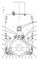
- Out the pressure chamber 11 is the detergent through the Cap lines 10 fed to the cap mouths 13. Out This cap mouths 13 occurs before the detergent Workpiece 2 adjacent scraping edges 14 of the Chip protection caps 9, the cap lines 10 with their cap mouths 13 to opposite the tread tangential release of the detergent and are oriented.
- the middle holding member 5 is relative to the workpiece 2 straight adjustable. Adjacent to this middle one Holding member 5 is in the bezel body 7 by one Cover 15 having outlet openings 17 covered, recess 16 connected to the detergent reservoir trained, these in the in the drawing illustrated embodiment on both sides of the middle Holding member 5 is formed, in FIG. 1 in the drawing level above and below the middle Retaining member 5.
- the outlet opening 17 is in the Cover 15 always on the middle holding member 5 facing side arranged.
- two coolant outlet openings 18th formed, which also the contact surface of the roller 3 keep the workpiece 2 free of chips, namely regardless of the direction of rotation.
- Dependence of the orientation of the bezel 1 in the Usually an installation position deviating from the horizontal has the recess 16 not required by a Stopper be closed.
Landscapes
- Engineering & Computer Science (AREA)
- Mechanical Engineering (AREA)
- Auxiliary Devices For Machine Tools (AREA)
- Jigs For Machine Tools (AREA)
- Turning (AREA)
- Lubricants (AREA)
- Fittings On The Vehicle Exterior For Carrying Loads, And Devices For Holding Or Mounting Articles (AREA)
- Machine Tool Units (AREA)
- Cleaning By Liquid Or Steam (AREA)
Abstract
Description
- Fig. 1
- eine Ansicht der erfindungsgemäßen Lünette in Längsrichtung des Werkstückes mit diesem nicht anliegenden Laufrollen,
- Fig. 2
- eine der Darstellung der Fig. 1 entsprechenden Teilansicht der erfindungsgemäßen Lünette mit dem Werkstück anliegenden Laufrollen,
- Fig. 3
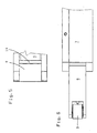
- der Schnitt III-III aus Fig. 1,
- Fig. 4
- der Schnitt IV-IV aus Fig. 1,
- Fig. 5
- eine Sicht aus Richtung des Pfeiles V aus Fig. 1, und
- Fig. 6
- eine Draufsicht auf einen im Lünettenkörper gelagerten Spannarm.
Claims (7)
- Lünette zum zentrischen Spannen von stangenförmigen Werkstücken (2) kreisförmigen Durchmessers an einer Drehmaschine, mit drei in einer gemeinsamen Ebene angeordneten, Laufrollen (3) aufweisenden Haltegliedern (4, 5), von denen die zwei äußeren Halteglieder (4) Spannarmen (6) zugeordnet sind, die um im Lünettenkörper (7) angeordnete Gelenkbolzen (8) verschwenkbar sind, und das mittlere Halteglied (5) relativ zum Werkstück (2) geradlinig verstellbar ist, ferner mit an den Spannarmen (6) angeordneten Späneschutzkappen (9) zur Vermeidung des Eindringens von Spänen zwischen die Laufflächen der Laufrollen (3) und des Werkstücks (2), dadurch gekennzeichnet, daß in den Spannarmen (6) Spülmittelleitungen (12) zur Versorgung von in den Späneschutzkappen (9) ausgebildeten internen Kappenleitungen (10) vorgesehen sind, die das Spülmittel auf den Laufflächen freisetzende Kappenmündungen (13) aufweisen.
- Lünette nach Anspruch 1, dadurch gekennzeichnet, daß die Späneschutzkappen (9) in Umfangsrichtung der Laufrollen (3) verschiebbar an den Spannarmen (6) gelagert sind und für den Übertritt des Spülmittels aus den Spannarmen (6) in die Späneschutzkappen (9) ein der Mündung der Spülmittelleitungen (12) oder der internen Kappenleitungen (10) in dem anderen Bauteil gegenüberliegender Druckraum (11) ausgebildet ist.
- Lünette nach Anspruch 1 oder 2, dadurch gekennzeichnet, daß die Kappenleitungen (10) mit ihren Kappenmündungen (13) zur gegenüber der Lauffläche tangentialen Freisetzung des Spülmittels in den Späneschutzkappen (9) verlegt sind.
- Lünette nach einem der Ansprüche 1 bis 3, dadurch gekennzeichnet, daß benachbart zu dem mittleren Halteglied (5) im Lünettenkörper (7) eine durch einen Deckel (15) mit mindestens einer Austrittsöffnung (17) abgedeckte, mit dem Spülmittelreservoir verbundene Ausnehmung (16) ausgebildet ist.
- Lünette nach Anspruch 4, dadurch gekennzeichnet, daß die Ausnehmung (16) beidseits des mittleren Halteglieds (5) ausgebildet ist.
- Lünette nach Anspruch 5, dadurch gekennzeichnet, daß die in Abhängigkeit der Orientierung der Lünette (1) nicht benötigte Ausnehmung (16) durch einen Stopfen verschlossen ist.
- Lünette nach einem der Ansprüche 1 bis 6, dadurch gekennzeichnet, daß als Spülmittel das Kühlmittel vorgesehen ist.
Applications Claiming Priority (2)
| Application Number | Priority Date | Filing Date | Title |
|---|---|---|---|
| DE20012710U DE20012710U1 (de) | 2000-07-22 | 2000-07-22 | Lünette |
| DE20012710U | 2000-07-22 |
Publications (4)
| Publication Number | Publication Date |
|---|---|
| EP1174211A2 true EP1174211A2 (de) | 2002-01-23 |
| EP1174211A3 EP1174211A3 (de) | 2002-05-02 |
| EP1174211B1 EP1174211B1 (de) | 2003-10-08 |
| EP1174211B2 EP1174211B2 (de) | 2007-07-04 |
Family
ID=7944279
Family Applications (1)
| Application Number | Title | Priority Date | Filing Date |
|---|---|---|---|
| EP01110546A Expired - Lifetime EP1174211B2 (de) | 2000-07-22 | 2001-05-02 | Lünette |
Country Status (7)
| Country | Link |
|---|---|
| US (1) | US6505533B2 (de) |
| EP (1) | EP1174211B2 (de) |
| JP (1) | JP4897157B2 (de) |
| AT (1) | ATE251521T1 (de) |
| CZ (1) | CZ295493B6 (de) |
| DE (2) | DE20012710U1 (de) |
| ES (1) | ES2203562T5 (de) |
Cited By (2)
| Publication number | Priority date | Publication date | Assignee | Title |
|---|---|---|---|---|
| CN110625184A (zh) * | 2019-10-18 | 2019-12-31 | 乐开霞 | 一种钢管剪切加工过程所使用的钢管同心夹持工装 |
| CN110814803A (zh) * | 2019-11-20 | 2020-02-21 | 吴海峰 | 一种多尺寸机械五金件钻孔用辅助夹具 |
Families Citing this family (22)
| Publication number | Priority date | Publication date | Assignee | Title |
|---|---|---|---|---|
| US7337698B2 (en) * | 2005-04-22 | 2008-03-04 | S & D Machine And Tool | Adjustable pipe shaving device |
| EP1946884B1 (de) * | 2007-01-20 | 2008-12-24 | SMW-Autoblok Spannsysteme GmbH | Lünette |
| PL1997583T3 (pl) * | 2007-05-26 | 2009-08-31 | Smw Autoblok Spannsysteme Gmbh | Okular |
| DE102007029492B3 (de) * | 2007-06-26 | 2009-01-29 | Smw-Autoblok Spannsysteme Gmbh | Lünette |
| EP2353777B1 (de) * | 2010-02-08 | 2011-12-21 | SMW-AUTOBLOK Spannsysteme GmbH | Selbstzentrierende Lünette |
| ES2423918T3 (es) * | 2011-07-01 | 2013-09-25 | Smw-Autoblok Spannsysteme Gmbh | Luneta |
| DE102011051821A1 (de) * | 2011-07-13 | 2013-01-17 | Röhm Gmbh | Lünette mit Elektroantrieb |
| CN102554644B (zh) * | 2011-12-23 | 2014-12-24 | 苏州工业职业技术学院 | 一种齿条传动活塞压铸件的专用夹具 |
| US9310179B2 (en) | 2012-02-01 | 2016-04-12 | Seagate Technology Llc | Spindle force actuator |
| WO2014020050A1 (de) * | 2012-07-31 | 2014-02-06 | Sms Meer Gmbh | Rohrendenbearbeitungsmaschine mit einer zentriervorrichtung zum zentrieren eines rohrförmigen werkstücks relativ zu einer drehachse |
| US9162290B2 (en) * | 2013-04-04 | 2015-10-20 | Caterpillar Inc. | Center spacer between workpiece and dead center of machine tool |
| CN103264363B (zh) * | 2013-06-07 | 2015-07-15 | 南京埃尔法电液技术有限公司 | 一种液压驱动自动定心管件夹紧装置 |
| CN103481071A (zh) * | 2013-09-16 | 2014-01-01 | 苏州工业职业技术学院 | 一种活塞压铸件的专用夹具及其使用方法 |
| TWM476021U (en) * | 2013-11-01 | 2014-04-11 | Alex-Tech Machinery Industrial Co Ltd | Central rack device of CNC machine tool |
| EP2921260B1 (de) * | 2014-03-20 | 2016-08-31 | UNIVER S.p.A. | Pneumatisch betreibbares Arbeitsgerät |
| EP3093103B1 (de) * | 2015-05-12 | 2017-07-12 | SMW-Autoblok Spannsysteme GmbH | Lünette |
| CZ2015803A3 (cs) | 2015-11-10 | 2017-03-08 | S.A.M. - metalizaÄŤnĂ spoleÄŤnost, s.r.o. | Způsob obrábění povrchu rotačních součástí a zařízení k provádění tohoto způsobu |
| EP3456464B1 (de) * | 2017-09-15 | 2022-10-19 | AFW Holding GmbH | Vorrichtung mit lünette |
| DE202018103392U1 (de) * | 2018-06-15 | 2018-06-26 | PF Schweißtechnologie GmbH | Schälgerät |
| CN112318367A (zh) * | 2020-11-09 | 2021-02-05 | 上海中船三井造船柴油机有限公司 | 船用柴油机活塞杆定位支撑用中心架及其校调方法 |
| CN112453955B (zh) * | 2020-11-18 | 2022-10-04 | 江苏惠新知识产权服务有限公司 | 一种基于物联网的用于工业生产的智能切割设备 |
| CN114888318A (zh) * | 2022-05-30 | 2022-08-12 | 河南四方达超硬材料股份有限公司 | 一种刀具体、刀具的内冷通道成型方法 |
Family Cites Families (13)
| Publication number | Priority date | Publication date | Assignee | Title |
|---|---|---|---|---|
| US3889520A (en) * | 1973-02-13 | 1975-06-17 | Theodor Stoferle | Fluidic system for monitoring machine tool wear during a machining operation |
| DE3109974C2 (de) * | 1981-03-14 | 1983-05-19 | SMW Schneider & Weißhaupt GmbH, 7996 Meckenbeuren | Einrichtung zum Abstützen eines zylinderförmigen Werkstückes auf einer Drehmaschine mit einem Späneschutz |
| JPS6097242U (ja) * | 1983-12-07 | 1985-07-02 | 大昭和精機株式会社 | 回転切削工具用給油装置 |
| US4650237A (en) * | 1985-07-25 | 1987-03-17 | Arobotech Systems, Inc. | Automatic centering and gripper apparatus |
| US4631995A (en) * | 1985-11-18 | 1986-12-30 | Vroenen John J | Tooling apparatus |
| DE3544961A1 (de) * | 1985-12-19 | 1987-07-02 | Smw Spanneinrichtungen | Selbstzentrierende luenette |
| US4831782A (en) * | 1986-11-04 | 1989-05-23 | The Pratt & Whitney Co., Inc. | Apparatus for grinding a workpiece |
| JP2963122B2 (ja) * | 1989-11-30 | 1999-10-12 | 昭和アルミニウム株式会社 | 管材のクランプ固定装置 |
| IL99297A (en) * | 1991-08-26 | 1995-11-27 | Iscar Ltd | Sealing bushing for the shaft for a work piece |
| US5237780A (en) * | 1992-02-04 | 1993-08-24 | Arobotech Systems, Inc. | Steady rest with internal centerline adjustment |
| US5540526A (en) * | 1994-09-06 | 1996-07-30 | Leblond Makino Machine Tool Company | Fluid bearing tool and a method for forming the same |
| JP3595623B2 (ja) * | 1996-04-18 | 2004-12-02 | 株式会社アマダ | レーザ加工装置 |
| DE69931936T2 (de) * | 1998-09-08 | 2007-02-15 | Makino Inc., Mason | Schneidwerkzeug |
-
2000
- 2000-07-22 DE DE20012710U patent/DE20012710U1/de not_active Expired - Lifetime
-
2001
- 2001-05-02 EP EP01110546A patent/EP1174211B2/de not_active Expired - Lifetime
- 2001-05-02 ES ES01110546T patent/ES2203562T5/es not_active Expired - Lifetime
- 2001-05-02 DE DE50100745T patent/DE50100745D1/de not_active Expired - Fee Related
- 2001-05-02 AT AT01110546T patent/ATE251521T1/de not_active IP Right Cessation
- 2001-07-13 CZ CZ20012580A patent/CZ295493B6/cs not_active IP Right Cessation
- 2001-07-20 US US09/910,468 patent/US6505533B2/en not_active Expired - Fee Related
- 2001-07-23 JP JP2001222262A patent/JP4897157B2/ja not_active Expired - Fee Related
Cited By (3)
| Publication number | Priority date | Publication date | Assignee | Title |
|---|---|---|---|---|
| CN110625184A (zh) * | 2019-10-18 | 2019-12-31 | 乐开霞 | 一种钢管剪切加工过程所使用的钢管同心夹持工装 |
| CN110625184B (zh) * | 2019-10-18 | 2020-10-30 | 泉州台商投资区笙沓新材料有限公司 | 一种钢管剪切加工过程所使用的钢管同心夹持工装 |
| CN110814803A (zh) * | 2019-11-20 | 2020-02-21 | 吴海峰 | 一种多尺寸机械五金件钻孔用辅助夹具 |
Also Published As
| Publication number | Publication date |
|---|---|
| EP1174211B2 (de) | 2007-07-04 |
| DE20012710U1 (de) | 2000-11-23 |
| ES2203562T5 (es) | 2008-02-16 |
| DE50100745D1 (de) | 2003-11-13 |
| EP1174211A3 (de) | 2002-05-02 |
| US6505533B2 (en) | 2003-01-14 |
| JP2002086326A (ja) | 2002-03-26 |
| CZ20012580A3 (cs) | 2002-07-17 |
| ATE251521T1 (de) | 2003-10-15 |
| CZ295493B6 (cs) | 2005-08-17 |
| ES2203562T3 (es) | 2004-04-16 |
| US20020029668A1 (en) | 2002-03-14 |
| EP1174211B1 (de) | 2003-10-08 |
| JP4897157B2 (ja) | 2012-03-14 |
Similar Documents
| Publication | Publication Date | Title |
|---|---|---|
| EP1174211B1 (de) | Lünette | |
| DE69732157T2 (de) | Transportroboter mit Tropfwasserschutz | |
| EP1020894B1 (de) | Vorrichtung zur Ätzbehandlung eines scheibenförmigen Gegenstandes | |
| DE2940864A1 (de) | Vorrichtung zum festklemmen einer gleitfuehrung insbesondere schwalbenschwanzfuehrung | |
| DE4034695A1 (de) | Spruehduese | |
| EP1360924A2 (de) | Rucksack-Auftragegerät | |
| DE1928203B2 (de) | Haltevorrichtung fuer flaechige werkstuecke | |
| DE10345690A1 (de) | Werkzeughalter mit Klemmstift | |
| EP3860821A1 (de) | Absaugvorrichtung für eine kernbohreinrichtung | |
| AT16570U1 (de) | Drehwerkzeug-Halter | |
| DE102017103520A1 (de) | Stechschwert | |
| WO2008098952A1 (de) | Vorrichtung zur behandlung von wasser, insbesondere filtervorrichtung, und kartusche | |
| DE60211474T2 (de) | Ventil-modul für farbvorrichtung | |
| EP3860820A1 (de) | Absaugvorrichtung für eine kernbohreinrichtung | |
| DE69000612T2 (de) | Stecker fuer kabel aus optischen fasern. | |
| EP0515449A1 (de) | Vorrichtung zum schneiden und reinigen von gegenständen mittels eines wasser-abrasivmittel-gemisches bei hohem umgebungsdruck. | |
| DE3625074C2 (de) | ||
| DE20001587U1 (de) | Ausblaseinrichtung für eine Mehrfachkupplung | |
| DD141661A1 (de) | Vakuumspanneinrichtung zum transport von halbleiterscheiben | |
| DE3109974A1 (de) | Einrichtung zum aufspannen und/oder zur halterung eines werkstueckes auf einer drehmaschine | |
| DE29710458U1 (de) | Wiederverwendbares Verschlußelement | |
| DE19859468C2 (de) | Vorrichtung zum Behandeln und Handhaben von Substraten | |
| DE726780C (de) | Federnder Werkzeughalter | |
| DE9206803U1 (de) | Rohrhalterung | |
| DE102011001237A1 (de) | Tiefenanschlag zum Einsatz in einem Werkzeughalter und eine Anordnung zur Übergabe von Kühl- und/oder Schmiermittel von einem Werkzeughalter an ein Werkzeug |
Legal Events
| Date | Code | Title | Description |
|---|---|---|---|
| PUAI | Public reference made under article 153(3) epc to a published international application that has entered the european phase |
Free format text: ORIGINAL CODE: 0009012 |
|
| AK | Designated contracting states |
Kind code of ref document: A2 Designated state(s): AT BE CH CY DE DK ES FI FR GB GR IE IT LI LU MC NL PT SE TR |
|
| AX | Request for extension of the european patent |
Free format text: AL;LT;LV;MK;RO;SI |
|
| PUAL | Search report despatched |
Free format text: ORIGINAL CODE: 0009013 |
|
| AK | Designated contracting states |
Kind code of ref document: A3 Designated state(s): AT BE CH CY DE DK ES FI FR GB GR IE IT LI LU MC NL PT SE TR |
|
| AX | Request for extension of the european patent |
Free format text: AL;LT;LV;MK;RO;SI |
|
| RIC1 | Information provided on ipc code assigned before grant |
Free format text: 7B 23Q 1/76 A, 7B 23Q 11/00 B, 7B 23Q 11/08 B |
|
| 17P | Request for examination filed |
Effective date: 20020525 |
|
| GRAH | Despatch of communication of intention to grant a patent |
Free format text: ORIGINAL CODE: EPIDOS IGRA |
|
| AKX | Designation fees paid |
Free format text: AT BE CH CY DE DK ES FI FR GB GR IE IT LI LU MC NL PT SE TR |
|
| GRAH | Despatch of communication of intention to grant a patent |
Free format text: ORIGINAL CODE: EPIDOS IGRA |
|
| GRAA | (expected) grant |
Free format text: ORIGINAL CODE: 0009210 |
|
| AK | Designated contracting states |
Kind code of ref document: B1 Designated state(s): AT BE CH CY DE DK ES FI FR GB GR IE IT LI LU MC NL PT SE TR |
|
| PG25 | Lapsed in a contracting state [announced via postgrant information from national office to epo] |
Ref country code: NL Free format text: LAPSE BECAUSE OF FAILURE TO SUBMIT A TRANSLATION OF THE DESCRIPTION OR TO PAY THE FEE WITHIN THE PRESCRIBED TIME-LIMIT Effective date: 20031008 Ref country code: TR Free format text: LAPSE BECAUSE OF FAILURE TO SUBMIT A TRANSLATION OF THE DESCRIPTION OR TO PAY THE FEE WITHIN THE PRESCRIBED TIME-LIMIT Effective date: 20031008 Ref country code: IE Free format text: LAPSE BECAUSE OF FAILURE TO SUBMIT A TRANSLATION OF THE DESCRIPTION OR TO PAY THE FEE WITHIN THE PRESCRIBED TIME-LIMIT Effective date: 20031008 Ref country code: GB Free format text: LAPSE BECAUSE OF FAILURE TO SUBMIT A TRANSLATION OF THE DESCRIPTION OR TO PAY THE FEE WITHIN THE PRESCRIBED TIME-LIMIT Effective date: 20031008 Ref country code: FI Free format text: LAPSE BECAUSE OF FAILURE TO SUBMIT A TRANSLATION OF THE DESCRIPTION OR TO PAY THE FEE WITHIN THE PRESCRIBED TIME-LIMIT Effective date: 20031008 Ref country code: FR Free format text: LAPSE BECAUSE OF FAILURE TO SUBMIT A TRANSLATION OF THE DESCRIPTION OR TO PAY THE FEE WITHIN THE PRESCRIBED TIME-LIMIT Effective date: 20031008 Ref country code: CY Free format text: LAPSE BECAUSE OF FAILURE TO SUBMIT A TRANSLATION OF THE DESCRIPTION OR TO PAY THE FEE WITHIN THE PRESCRIBED TIME-LIMIT Effective date: 20031008 |
|
| REG | Reference to a national code |
Ref country code: GB Ref legal event code: FG4D Free format text: NOT ENGLISH |
|
| REG | Reference to a national code |
Ref country code: CH Ref legal event code: EP |
|
| REG | Reference to a national code |
Ref country code: IE Ref legal event code: FG4D Free format text: GERMAN |
|
| REF | Corresponds to: |
Ref document number: 50100745 Country of ref document: DE Date of ref document: 20031113 Kind code of ref document: P |
|
| PG25 | Lapsed in a contracting state [announced via postgrant information from national office to epo] |
Ref country code: DK Free format text: LAPSE BECAUSE OF FAILURE TO SUBMIT A TRANSLATION OF THE DESCRIPTION OR TO PAY THE FEE WITHIN THE PRESCRIBED TIME-LIMIT Effective date: 20040108 Ref country code: SE Free format text: LAPSE BECAUSE OF FAILURE TO SUBMIT A TRANSLATION OF THE DESCRIPTION OR TO PAY THE FEE WITHIN THE PRESCRIBED TIME-LIMIT Effective date: 20040108 Ref country code: GR Free format text: LAPSE BECAUSE OF FAILURE TO SUBMIT A TRANSLATION OF THE DESCRIPTION OR TO PAY THE FEE WITHIN THE PRESCRIBED TIME-LIMIT Effective date: 20040108 |
|
| NLV1 | Nl: lapsed or annulled due to failure to fulfill the requirements of art. 29p and 29m of the patents act | ||
| GBV | Gb: ep patent (uk) treated as always having been void in accordance with gb section 77(7)/1977 [no translation filed] |
Effective date: 20031008 |
|
| REG | Reference to a national code |
Ref country code: ES Ref legal event code: FG2A Ref document number: 2203562 Country of ref document: ES Kind code of ref document: T5 |
|
| PG25 | Lapsed in a contracting state [announced via postgrant information from national office to epo] |
Ref country code: LU Free format text: LAPSE BECAUSE OF NON-PAYMENT OF DUE FEES Effective date: 20040502 |
|
| PG25 | Lapsed in a contracting state [announced via postgrant information from national office to epo] |
Ref country code: BE Free format text: LAPSE BECAUSE OF NON-PAYMENT OF DUE FEES Effective date: 20040531 Ref country code: MC Free format text: LAPSE BECAUSE OF NON-PAYMENT OF DUE FEES Effective date: 20040531 |
|
| REG | Reference to a national code |
Ref country code: IE Ref legal event code: FD4D |
|
| PLBQ | Unpublished change to opponent data |
Free format text: ORIGINAL CODE: EPIDOS OPPO |
|
| PLBI | Opposition filed |
Free format text: ORIGINAL CODE: 0009260 |
|
| 26 | Opposition filed |
Opponent name: SMW-AUTOBLOK SPANNSYSTEME GMBH Effective date: 20040701 |
|
| EN | Fr: translation not filed | ||
| BERE | Be: lapsed |
Owner name: *ROHM G.M.B.H. Effective date: 20040531 |
|
| PLAX | Notice of opposition and request to file observation + time limit sent |
Free format text: ORIGINAL CODE: EPIDOSNOBS2 |
|
| PLBB | Reply of patent proprietor to notice(s) of opposition received |
Free format text: ORIGINAL CODE: EPIDOSNOBS3 |
|
| PG25 | Lapsed in a contracting state [announced via postgrant information from national office to epo] |
Ref country code: LI Free format text: LAPSE BECAUSE OF NON-PAYMENT OF DUE FEES Effective date: 20050531 Ref country code: CH Free format text: LAPSE BECAUSE OF NON-PAYMENT OF DUE FEES Effective date: 20050531 |
|
| REG | Reference to a national code |
Ref country code: CH Ref legal event code: PL |
|
| PGFP | Annual fee paid to national office [announced via postgrant information from national office to epo] |
Ref country code: AT Payment date: 20070531 Year of fee payment: 7 |
|
| PUAH | Patent maintained in amended form |
Free format text: ORIGINAL CODE: 0009272 |
|
| STAA | Information on the status of an ep patent application or granted ep patent |
Free format text: STATUS: PATENT MAINTAINED AS AMENDED |
|
| 27A | Patent maintained in amended form |
Effective date: 20070704 |
|
| AK | Designated contracting states |
Kind code of ref document: B2 Designated state(s): AT BE CH CY DE DK ES FI FR GB GR IE IT LI LU MC NL PT SE TR |
|
| PG25 | Lapsed in a contracting state [announced via postgrant information from national office to epo] |
Ref country code: PT Free format text: LAPSE BECAUSE OF NON-PAYMENT OF DUE FEES Effective date: 20040308 |
|
| REG | Reference to a national code |
Ref country code: ES Ref legal event code: DC2A Date of ref document: 20071003 Kind code of ref document: T5 |
|
| EN | Fr: translation not filed | ||
| PG25 | Lapsed in a contracting state [announced via postgrant information from national office to epo] |
Ref country code: AT Free format text: LAPSE BECAUSE OF NON-PAYMENT OF DUE FEES Effective date: 20080502 |
|
| PGFP | Annual fee paid to national office [announced via postgrant information from national office to epo] |
Ref country code: ES Payment date: 20090522 Year of fee payment: 9 |
|
| PGFP | Annual fee paid to national office [announced via postgrant information from national office to epo] |
Ref country code: DE Payment date: 20090610 Year of fee payment: 9 Ref country code: IT Payment date: 20090526 Year of fee payment: 9 |
|
| PG25 | Lapsed in a contracting state [announced via postgrant information from national office to epo] |
Ref country code: IT Free format text: LAPSE BECAUSE OF NON-PAYMENT OF DUE FEES Effective date: 20100502 |
|
| PG25 | Lapsed in a contracting state [announced via postgrant information from national office to epo] |
Ref country code: DE Free format text: LAPSE BECAUSE OF NON-PAYMENT OF DUE FEES Effective date: 20101201 |
|
| REG | Reference to a national code |
Ref country code: ES Ref legal event code: FD2A Effective date: 20110714 |
|
| PG25 | Lapsed in a contracting state [announced via postgrant information from national office to epo] |
Ref country code: ES Free format text: LAPSE BECAUSE OF NON-PAYMENT OF DUE FEES Effective date: 20110704 |
|
| PG25 | Lapsed in a contracting state [announced via postgrant information from national office to epo] |
Ref country code: ES Free format text: LAPSE BECAUSE OF NON-PAYMENT OF DUE FEES Effective date: 20100503 |