EP1174072A2 - Anordnung eines Filterbeutels in einem Elektrostaubsauger sowie Filterbeutel mit einer Halteplatte - Google Patents
Anordnung eines Filterbeutels in einem Elektrostaubsauger sowie Filterbeutel mit einer Halteplatte Download PDFInfo
- Publication number
- EP1174072A2 EP1174072A2 EP01116652A EP01116652A EP1174072A2 EP 1174072 A2 EP1174072 A2 EP 1174072A2 EP 01116652 A EP01116652 A EP 01116652A EP 01116652 A EP01116652 A EP 01116652A EP 1174072 A2 EP1174072 A2 EP 1174072A2
- Authority
- EP
- European Patent Office
- Prior art keywords
- filter bag
- holding plate
- actuating section
- section
- particular according
- Prior art date
- Legal status (The legal status is an assumption and is not a legal conclusion. Google has not performed a legal analysis and makes no representation as to the accuracy of the status listed.)
- Granted
Links
Images


Classifications
-
- A—HUMAN NECESSITIES
- A47—FURNITURE; DOMESTIC ARTICLES OR APPLIANCES; COFFEE MILLS; SPICE MILLS; SUCTION CLEANERS IN GENERAL
- A47L—DOMESTIC WASHING OR CLEANING; SUCTION CLEANERS IN GENERAL
- A47L9/00—Details or accessories of suction cleaners, e.g. mechanical means for controlling the suction or for effecting pulsating action; Storing devices specially adapted to suction cleaners or parts thereof; Carrying-vehicles specially adapted for suction cleaners
- A47L9/10—Filters; Dust separators; Dust removal; Automatic exchange of filters
- A47L9/14—Bags or the like; Rigid filtering receptacles; Attachment of, or closures for, bags or receptacles
- A47L9/1427—Means for mounting or attaching bags or filtering receptacles in suction cleaners; Adapters
- A47L9/1436—Connecting plates, e.g. collars, end closures
-
- A—HUMAN NECESSITIES
- A47—FURNITURE; DOMESTIC ARTICLES OR APPLIANCES; COFFEE MILLS; SPICE MILLS; SUCTION CLEANERS IN GENERAL
- A47L—DOMESTIC WASHING OR CLEANING; SUCTION CLEANERS IN GENERAL
- A47L9/00—Details or accessories of suction cleaners, e.g. mechanical means for controlling the suction or for effecting pulsating action; Storing devices specially adapted to suction cleaners or parts thereof; Carrying-vehicles specially adapted for suction cleaners
- A47L9/10—Filters; Dust separators; Dust removal; Automatic exchange of filters
- A47L9/19—Means for monitoring filtering operation
Definitions
- the invention first relates to the arrangement of a Filter bag in an electric vacuum cleaner, the Filter bag has a holding plate that has an opening for the entry of dust into the filter bag and a deflectable one assigned to the edge side Has section that in the course of inserting the filter bag can be deflected into the electric vacuum cleaner, the electric vacuum cleaner a level indicator for the level of the filter bag in the electric vacuum cleaner has, with an indicator piston, the indicator piston movable by pressure difference on the filter bag is and has a piston skirt with a catch hook.
- an actuating element in the form of a deflectable actuating section which has sufficient tolerance compensation so that interaction with the level indicator or its catch hook is possible even in the case of an unfavorable pairing of the tolerances of the holding plate and holding plate holder in the device.
- the actuating section is arranged associated with an edge side of the filter bag or its holding plate, the actuating section being cut freely to the edge of the holding plate or being arranged in a bulge in the holding plate. When the actuating section is arranged in the region of a bulge in the holding plate, it is enclosed in a ring or fork shape.
- the actuating section Due to the fact that the actuating section is manufactured with a certain oversize, an interaction with the level indicator is possible even with an unfavorable tolerance pairing.
- the excess of the actuating section causes a deformation of the actuating section in the course of inserting the filter bag into the filter chamber, after which the latter is deflected upwards with its free edge, preferably running essentially parallel to the steering axis. This is due to a collision with the housing protruding upwards above the holding plate and / or the catch hook. It is furthermore advantageous due to the configuration according to the invention that the deflection of the actuating section in the course of inserting the filter bag via the deflected actuating section gives the user an indication that this filter bag has already been used.
- the actuation section can - as already mentioned - be enclosed in a ring or fork shape.
- the actuating section is deflected by a housing section which extends in overlap with the catch hook below the catch hook.
- This housing section can be formed in the form of a rib protruding from the level indicator housing, against the upper edge of which the actuating section of the filter bag is deflected in the course of its insertion or in the course of a displacement of the filter bag into an operating position.
- the catch hook can be hooked onto a side wall of the housing below a housing cover, which side wall has an opening in this regard, while penetrating the side wall.
- the filter bag inserted with the actuating section deflected upwards acts upon this actuating section in the course of removing the filter bag from the catch hook, which at maximum fill level has passed through the housing opening and locks there in such a way that it is displaced through the opening back into the housing, to initiate a reset to the basic level indicator.
- the catch hook preferably has a deflection slope pointing downward, ie in the direction of the actuation section deflected upwards.
- the level indicator is reset when the filled filter bag is removed.
- the reset can also be carried out by inserting a preferably new, unused filter bag.
- the actuating section which is preferably initially aligned in one plane to the holding plate of the filter bag, is deflected by being acted upon by the level indicator housing, whereupon it acts on the catch hook which has passed through the housing opening in the course of the further inward displacement of the filter bag. The latter is thereby moved back due to the housing opening.
- the actuating section In the operating position of the filter bag, the actuating section remains in the deflected position, preferably by contacting the housing section, for example the rib, in a position directed by approximately 90 ° to the holding plate extension.
- the housing section or the rib serves to guide the deflected actuating section past the catch hook that has passed through the housing opening.
- the operating section ends below the housing cover in the operating position.
- the free edge edge ends below the housing ceiling in this operating position, this free edge edge being the edge edge which is opposite the pivot axis of the actuating section and which is to be acted upon by the catch pawls for resetting the same.
- the free edge ends in the operating position below the hook is also proposed that the free edge ends in the operating position below the hook.
- the holding plate has a rectangular outline, with a longer and a shorter side, and that the actuating section is pivoted about an axis corresponding to the orientation of the shorter side.
- the actuating section is assigned to a corner region of the holding plate, so further preferably in a first third of the longitudinal edge side of the holding plate in the longitudinal extent of the holding plate.
- this is part of the holding plate.
- the actuating section consists of the cardboard / paper material of the holding plate.
- a holding plate made of cardboard / paper material usually consists of several, for example three or four layers. In order to form a deflectable actuating section here, it can be formed, for example, only over one layer.
- the actuating section in addition, it is conceivable to form the actuating section by perforation, pre-break or compression in the area of the holding plate, so that a predetermined deformation is made possible. Furthermore, it is also conceivable to connect the actuating section to the holding plate via an elastic connecting member. It is also conceivable that, in the case of a holding plate to which a dust filter bag is attached, the actuating section is formed from a part of the dust filter bag, for example in an area of the dust filter bag which is folded in the fastening area of the holding plate and is therefore slightly stiffened. Finally, it is also conceivable that the actuating section consists of a flexible membrane.
- the invention further relates to a filter bag with a holding plate, which holding plate one of the Has edge-associated, deflectable section.
- the edge section is designed as an actuating section.
- the latter is preferably used to interact with a level indicator in one that holds the filter bag Housing of an electric vacuum cleaner.
- the Actuating section towards the edge of the filter bag be freely trained.
- Actuating section with a short distance to Arrange the edge of the filter bag for example in an edge-side, ring-shaped or fork-shaped Area of the filter bag.
- the operating section is deflectable.
- the holding plate has a rectangular plan, with a longer and a shorter side and that the actuating section by one of the orientation of the shorter side corresponding axis is pivotable.
- the operating section a corner area of the Holding plate is assigned, so further preferred in one - viewed in the longitudinal extent of the holding plate - First third of the longitudinal edge side of the holding plate.
- the Actuating section is part of the holding plate, wherein in this regard, it is further proposed that the operating section made of cardboard / paper material Holding plate is there. Holding plates made of cardboard / paper material usually consist of several, for example from three or four layers.
- the deflectable operating section is preferably formed from a Position of the holding plate, whereby a predetermined pivot axis in the transition area from the single layer Actuating section to the multi-layer holding plate is predetermined.
- the deflectability of the actuating section can also be caused by perforation, pre-opening or Compression of the cardboard / paper material has been reached.
- the actuating section made of a flexible membrane consists.
- Is shown and described initially with reference to 1 shows an electric vacuum cleaner with a vacuum cleaner housing S and a filter bag 35 with one Holding plate 36 receiving filter chamber K.
- a level indicator 1 for the level of the filter bag 35 arranged.
- the fill level indicator 1 has a, possibly transparent Housing 2 on an indicator piston 3, the latter is designed as a membrane piston 4. Is concrete the design chosen so that the membrane piston 4 is composed of, for example, hard plastic formed indicator piston 3 and a sealing attached to the outer wall of the indicator piston 3, tubular and elastic soft membrane 5.
- the soft membrane 5 is in the area of one in the housing 2 arranged intermediate floor 6 sealed.
- the free end of the piston shaft facing away from the indicator piston 3 7 is provided with a radial collar 9, against which there is one, the piston skirt 7 Compression spring 10 is supported at one end.
- the other end of the Compression spring 10 occurs in the area of the self-aligning bearing or opening 8 on the underside against the intermediate floor 6, whereby the compression spring 10 has the function of a return spring for the indicator piston 3 takes over.
- the piston shaft 7 is beyond the indicator piston extended to form a hook 30.
- the latter runs opposite the piston shaft axis slightly inclined.
- the housing 2 is in the region of the catch hook shaft 30 opposite the area surrounding the membrane piston 4 tapered in cross-section, this tapered in cross-section Area closed by a housing cover 24 is.
- the catch hook 11 points downward pointing deflection slope 33, which in the direction of the catch hook shaft 30 merges into a flat 34.
- the depth of this flattening 34 is selected such that with the catch hook shaft 30 inside the Housing 2 the foot line of the subsequent deflection slope 33 coincides with an outer edge the housing opening 31.
- the catch hook is opposite the deflecting bevel 33 11 flattened, preferably approximately parallel to the alignment the ceiling 24 is trending.
- the membrane piston which is sealed in the housing 2 4 are two pressure chambers 13 and 14 in the housing 2 educated.
- the catch hook 11 facing pressure chamber 14 protrudes a housing opening formed in the area of the housing step 15 in connection with the filter bag exterior. Accordingly, the pressure potential in the pressure chamber corresponds 14 that of the air flow direction behind the Filter bag measured pressure potential.
- the pressure chamber assigned to the underside of the soft membrane 5 13 stands over a housing bottom side, not shown Opening in connection with the inside of the filter bag, with which the pressure potential in the pressure chamber 13 corresponds to the pressure potential inside the filter bag.
- the function of the level indicator is as follows:
- the displacement of the indicator piston 3 is dependent from the pressure differences until the Catch hook 11 with its deflection bevels 12 in the opening 31 kicks and gets hooked there.
- the indicator piston is displaced vertically against the spring force of the return spring 10, the spring force is adapted to the usual pressure potential in the housing 2.
- Level indicator 1 shows the maximum permissible filling of the Dust filter bag. Over the fixed catch hook 11 can be switched off mechanically, for example of the vacuum cleaner. Is the maximum Level in the filter bag is not reached, so the indicator piston 3 does not get into the one that locks it Position what after turning off the vacuum cleaner a reset caused by the compression spring 10 of the indicator piston 3 and an associated Folding the membrane 5 into the rest position has the consequence.
- the housing 2 With a transparent configuration of the housing 2 can the level of the dust filter bag by means of Indicating piston 3 are shown. However, it is also possible, at any point on the indicator piston 3 or also the piston skirt 7 is a component for visualization to arrange the position.
- Intervention is only by separate Intervention can be canceled, for example by Deflection of the catch hook 11 in the direction of the interior of the housing.
- This horizontally acting force for example can be applied by inserting a new filter bag become.
- FIG. 3 to 7 show the interaction of the in Fig. 2 shown and described level indicator 1 with one to be inserted or inserted in the vacuum cleaner Filter bag 35.
- This filter bag 35 is essentially composed made of a cardboard / paper material, multilayer holding plate 36 and one on this attach dust filter bag 37.
- the holding plate 36 For the entry of dust in the dust bag 37 is the holding plate 36 with a Provide opening 38.
- the holding plate 36 has a substantially rectangular one Floor plan, with a longer side 39 and a shorter side 40.
- the longer edge side 39 is assigned an actuating section in the holding plate 36 41 forming, deflectable section 42 formed.
- This operating section 41 is in one Corner area of the holding plate 36, for example in a first Third of the long side 39 formed with a Pivot axis 43, which is the orientation of the shorter Page 40 is aligned accordingly.
- the operating section 41 is shown in FIG Embodiment formed by a layer of the Cardboard / paper material existing holding plate 36, the pivot axis 43 further being perforated, Pre-breaking, compression or the like weakened or provided with an elastic connecting link is, so that a predetermined deformation enables becomes.
- the actuating section 41 from part of the on the holding plate 36 attached dust filter bag 37 to form. Further can also the actuating section from a flexible Membrane exist.
- the filter bag 35 is in the vacuum cleaner too position that the operating section 41 of the Level indicator 1 is aligned facing.
- FIG. 3 schematically shows a situation in which the level indicator 1 in one Home position, d. H. in the non-locking position lingers and a new unused filter bag 35 with one aligned in one plane to the holding plate 36 Operating section 41 moved in the direction of insertion becomes.
- the oversized operating section 41 occurs in the course of the insertion movement of the filter bag 35 against the housing ceiling 24 of the level indicator 1 and will be changed in the course of the further relocation its pivot axis 43 deflected.
- the deflected section 42 lies with its free edge 44 on the outer wall of the Housing 2 below the side wall opening 31.
- the Catch hook 11 can consequently be reached when the maximum Fill level of the filter bag 35 unhindered in the Enter the side wall opening 31 into place.
- the filter bag 35 is in the use position in Overhead position in the, on the vacuum cleaner housing S pivoted filter chamber K held. Due to this protrudes the housing 2, in particular the locking area of the in the vacuum cleaner housing S arranged level indicator 1 over the holding plate 36 of the filter bag 35, further, the operating section 41 therein Position is deflected upwards.
- the level indicator 1 is thus reset in this embodiment when removing the filled filter bag 35.
- the operating section 41 may be as in FIG Fig. 8 shown in a bulge 45 of the holding plate 36 may be arranged so that the holding plate 36 the actuating section 41 in the form of a ring or fork encloses.
- FIG. 9 to 13 show a further embodiment the level indicator 1. This corresponds essentially that of the previously described embodiment. Only The catch hook 11 is also on the top here, d. H. the deflection slope 33 opposite with an upper one Deflection bevel 12 provided. Furthermore, on the Housing 2 on the outside, below the side wall opening 31 a rib 46 is formed, the extension of which in Radial direction of the housing 2 is chosen so that a Cover also in the locking position according to FIG. 9 outwardly projecting catch hook 11 is given.
- the catch hook 11 also acts preferentially here with a deflectable actuating section 41 of Filter bag holding plate 36 together.
- the user gets through the pivoted actuation section 41 is an indication placed on an already used filter bag 35.
- the triggering of the level indicator 1 is in this Embodiment in the course of inserting a new, unused filter bag 35 causes.
- Fig. 14 shows an embodiment of the level indicator 1 according to that in FIGS. 9 to 13 described embodiment in cooperation with the Catch hook 11 with a 45 in a bulge Holding plate 36 arranged actuating section 41 according to the embodiment of the holding plate 36 in FIG. 8.
Landscapes
- Engineering & Computer Science (AREA)
- Mechanical Engineering (AREA)
- Filters For Electric Vacuum Cleaners (AREA)
Abstract
Description
Eine aus Pappe-/Papierwerkstoff bestehende Halteplatte besteht in der Regel aus mehreren, so beispielsweise aus drei oder vier Lagen. Um hier einen auslenkbaren Betätigungsabschnitt auszubilden, kann dieser beispielsweise lediglich über eine Lage ausgebildet sein. Darüber hinaus ist es denkbar, den Betätigungsabschnitt durch Perforation, Vorbruch oder Verdichtung im Bereich der Halteplatte auszubilden, so dass eine vorbestimmte Verformung ermöglicht wird. Des Weiteren ist auch denkbar, den Betätigungsabschnitt über ein elastisches Verbindungsglied mit der Halteplatte zu verbinden. Zudem ist denkbar, dass bei einer Halteplatte, an welchem ein Staubfilterbeutel befestigt ist, der Betätigungsabschnitt aus einem Teil des Staubfilterbeutels gebildet ist, so beispielsweise in einem, im Befestigungsbereich der Halteplatte gefalteten und somit leicht ausgesteiftem Bereich des Staubfilterbeutels. Schließlich ist es auch denkbar, dass der Betätigungsabschnitt aus einer flexiblen Membran besteht.
- Fig. 1
- eine perspektivische Darstellung eines Elektrostaubsaugers, mit einer Filterkammer und einer Füllstandanzeige;
- Fig. 2
- eine schematische Schnittdarstellung durch eine Füllstandanzeige in einer ersten Ausführungsform, die, den maximalen Füllstand eines Filterbeutels anzeigende Raststellung betreffend;
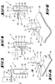
- Fig. 3
- eine geschnittene Detaildarstellung des Rastbereiches der Füllstandanzeige gemäß Fig. 2, die gelöste Stellung eines Fanghakens bei entnommenen Filterbeutel betreffend;
- Fig. 4
- eine der Fig. 3 entsprechende Darstellung, jedoch bei eingelegtem Filterbeutel und nach einem Verrasten des Fanghakens am Anzeigengehäuse;
- Fig. 5
- eine weitere der Fig. 3 entsprechende Darstellung, bei Beaufschlagung des Rasthakens im Zuge einer Filterbeutelentnahme;
- Fig. 6
- eine perspektivische Darstellung des Rastbereiches der Füllstandanzeige mit zugeordneter Filterbeutel-Halteplatte, die Stellung gemäß Fig. 4 betreffend;
- Fig. 7
- eine weitere perspektivische Darstellung, die Ausführungsform und Stellung gemäß Fig. 6 betreffend;
- Fig. 8
- eine der Fig. 6 entsprechende Darstellung mit einer Filterbeutel-Halteplatte in einer weiteren Ausführungsform;
- Fig. 9
- eine der Fig. 3 entsprechende Detaildarstellung, mit einer Füllstandanzeige in einer weiteren Ausführungsform, die verrastete Stellung des Fanghakens bei entnommenen Filterbeutel betreffend;
- Fig. 10
- eine der Fig. 9 entsprechende Darstellung, bei Beaufschlagung des Rasthakens im Zuge eines Einsetzen des Filterbeutels;
- Fig. 11
- eine der Fig. 3 entsprechende Darstellung, jedoch die Ausführungsform gemäß Fig. 9 betreffend;
- Fig. 12
- eine weitere Darstellung gemäß Fig. 9, im Zuge einer Herausverlagerung des Filterbeutels;
- Fig. 13
- eine der Fig. 6 entsprechende perspektivische Darstellung, die Stellung der weiteren Ausführungsform gemäß Fig. 11 betreffend;
- Fig. 14
- eine perspektivische Darstellung gemäß Fig. 13 mit einer Filterbeutel-Halteplatte gemäß der in Fig. 8 dargestellten Form.
Claims (20)
- Anordnung eines Filterbeutels (35) in einem Elektrostaubsauger, wobei der Filterbeutel (35) eine Halteplatte (36) besitzt, die eine Öffnung (38) für den Eintrag von Staub in den Filterbeutel (35) besitzt und einen der Randseite zugeordnete, auslenkbaren Abschnitt (42) aufweist, der im Zuge des Einlegens des Filterbeutels (35) in den Elektrostaubsauger auslenkbar ist, wobei der Elektrostaubsauger eine Füllstandanzeige (1) für den Füllstand des Filterbeutels (35) in dem Elektrostaubsauger aufweist, mit einem Anzeigekolben (3), wobei der Anzeigekolben (3) durch Druckdifferenz an dem Filterbeutel (35) bewegbar ist und einen Kolbenschaft (7) aufweist, mit einem Fanghaken (11), dadurch gekennzeichnet, dass der Fanghaken (11) an einer Gehäusewand unter deren Durchdringung verhakbar ist und dass der als Betätigungsabschnitt (41) ausgebildete, auslenkbare Abschnitt (42), der eine freie Randkante (44) aufweist, durch das nach oben über die Halteplatte (36) vorragende Gehäuse (2) und/oder den Fanghaken (11) nach oben ausgelenkt ist.
- Anordnung nach Anspruch 1 oder insbesondere danach, dadurch gekennzeichnet, dass der Betätigungsabschnitt (41) durch einen Gehäuseabschnitt, der sich in Überdekkung zu dem Fanghaken (11) unterhalb des Fanghakens (11) erstreckt, ausgelenkt ist.
- Anordnung nach einen oder mehreren der vorhergehenden Ansprüche oder insbesondere danach, dadurch gekennzeichnte, dass der Fanghaken (11) an einer Seitenwand (32) des Gehäuses (2) unterhalb der Gehäusedecke (24), welche Seitenwand (32) eine diesbezügliche Öffnung (31) aufweist, unter Durchsetzung der Seitenwand (32) verhakbar ist.
- Anordnung nach einem oder mehreren der vorhergehenden Ansprüche oder insbesondere danach, dadurch gekennzeichnet, dass der Betätigungsabschnitt (41) unterhalb der Gehäusedecke (24) endet.
- Anordnung nach einem oder mehreren der vorhergehenden Ansprüche oder insbesondere danach, dadurch gekennzeichnet, dass die freie Randkante (44) unterhalb der Gehäusedecke (24) endet.
- Anordnung nach einem oder mehreren der vorhergehenden Ansprüche oder insbesondere danach, dadurch gekennzeichnet, dass die freie Randkante (44) unterhalb des Fanghakens (11) endet.
- Anordnung nach einem oder mehreren der vorhergehenden Ansprüche oder insbesondere danach, dadurch gekennzeichnet, dass die Halteplatte (36) einen rechteckigen Grundriss aufweist, mit einer längeren (39) und einer kürzeren Seite (40) und dass der Betätigungsabschnitt (41) um eine der Ausrichtung der kürzeren Seite (40) entsprechenden Achse (43) verschwenkt ist.
- Anordnung nach einem oder mehreren der vorhergehenden Ansprüche oder insbesondere danach, dadurch gekennzeichnet, dass der Betätigungsabschnitt (41) einem Eckbereich der Halteplatte (36) zugeordnet ist.
- Anordnung nach einem oder mehreren der vorhergehenden Ansprüche oder insbesondere danach, dadurch gekennzeichnet, dass der Betätigungsabschnitt (41) Teil der Halteplatte (36) ist.
- Anordnung nach einem oder mehreren der vorhergehenden Ansprüche oder insbesondere danach, dadurch gekennzeichnet, dass der Betätigungsabschnitt (41) aus dem Pappe-/Papierwerkstoff der Halteplatte (36) besteht.
- Anordnung nach einem oder mehreren der vorhergehenden Ansprüche oder insbesondere danach, wobei an der Halteplatte (36) ein Staubfilterbeutel (37) befestigt ist, dadurch gekennzeichnet, dass der Betätigungsabschnitt (41) aus einem Teil des Staubfilterbeutels (37) gebildet ist.
- Anordnung nach einem oder mehreren der vorhergehenden Ansprüche oder insbesondere danach, dadurch gekennzeichnet, dass der Betätigungsabschnitt (41) aus einer flexiblen Membran besteht.
- Filterbeutel (35) mit einer Halteplatte (36), welche Halteplatte (36) einen der Randseite zugeordneten, auslenkbaren Abschnitt (42) aufweist, dadurch gekennzeichnet, dass der randseitige Abschnitt (42) als Betätigungsabschnitt (41) ausgebildet ist.
- Filterbeutel nach Anspruch 13 oder insbesondere danach, dadurch gekennzeichnet, dass der Betätigunsabschnitt (41) auslenkbar ist.
- Filterbeutel nach einem oder mehreren der Ansprüche 13 bis 14 oder insbesondere danach, dadurch gekennzeichnet, dass die Halteplatte (36) einen rechteckigen Grundriss aufweist, mit einer längeren (39) oder einer kürzeren Seite (40) und dass der Betätigungsabschnitt (41) um eine der Ausrichtung der kürzeren Seite (40) entsprechenden Achse (43) verschwenkbar ist.
- Filterbeutel nach einem oder mehreren der Ansprüche 13 bis 15 oder insbesondere danach, dadurch gekennzeichnet, dass der Betätigungsabschnitt (41) einem Eckbereich der Halteplatte (36) zugeordnet ist.
- Filterbeutel nach einem oder mehreren der Ansprüche 13 bis 16 oder insbesondere danach, dadurch gekennzeichnet, dass der Betätigungsabschnitt (41) Teil der Halteplatte (36) ist.
- Filterbeutel nach einem oder mehreren der Ansprüche 13 bis 17 oder insbesondere danach, dadurch gekennzeichnet, dass der Betätigungsabschnitt (41) aus dem Pappe-/Papierwerkstoff der Halteplatte (36) besteht.
- Filterbeutel nach einem oder mehreren der Ansprüche 13 bis 18 oder insbesondere danach, wobei an der Halteplatte (36) ein Staubfilterbeutel (37) befestigt ist, dadurch gekennzeichnet, dass der Betätigungsabschnitt (41) aus einem Teil des Staubfilterbeutels (37) gebildet ist.
- Filterbeutel nach einem oder mehreren der Ansprüche 13 bis 19 oder insbesondere danach, dadurch gekennzeichnet, dass der Betätigungsabschnitt (41) aus einer flexiblen Membran besteht.
Priority Applications (2)
| Application Number | Priority Date | Filing Date | Title |
|---|---|---|---|
| SI200130621T SI1174072T1 (sl) | 2000-07-20 | 2001-07-13 | Razporeditev filtrske vrecke v elektricnem sesalniku za prah kot tudi filtrska vrecka z drzalno plosco |
| DE20122118U DE20122118U1 (de) | 2000-07-20 | 2001-07-13 | Anordnung eines Filterbeutels in einem Elektrostaubsauger sowie Filterbeutel mit einer Halteplatte |
Applications Claiming Priority (2)
| Application Number | Priority Date | Filing Date | Title |
|---|---|---|---|
| DE10051304A DE10051304A1 (de) | 2000-07-20 | 2000-07-20 | Anordnung eines Filterbeutels in einem Elektrostaubsauger sowie Filterbeutel mit einer Halteplatte |
| DE10051304 | 2000-07-20 |
Publications (3)
| Publication Number | Publication Date |
|---|---|
| EP1174072A2 true EP1174072A2 (de) | 2002-01-23 |
| EP1174072A3 EP1174072A3 (de) | 2002-12-11 |
| EP1174072B1 EP1174072B1 (de) | 2006-06-07 |
Family
ID=7660008
Family Applications (1)
| Application Number | Title | Priority Date | Filing Date |
|---|---|---|---|
| EP01116652A Expired - Lifetime EP1174072B1 (de) | 2000-07-20 | 2001-07-13 | Anordnung eines Filterbeutels in einem Elektrostaubsauger sowie Filterbeutel mit einer Halteplatte |
Country Status (5)
| Country | Link |
|---|---|
| EP (1) | EP1174072B1 (de) |
| AT (1) | ATE328524T1 (de) |
| DE (2) | DE10051304A1 (de) |
| ES (1) | ES2262581T3 (de) |
| HK (1) | HK1044104A1 (de) |
Cited By (1)
| Publication number | Priority date | Publication date | Assignee | Title |
|---|---|---|---|---|
| EP1639933A2 (de) | 2004-09-24 | 2006-03-29 | Stein & Co. GmbH | Vorrichtung für Filterbeutel von Staubsaugern |
Families Citing this family (3)
| Publication number | Priority date | Publication date | Assignee | Title |
|---|---|---|---|---|
| DE20308543U1 (de) | 2003-05-31 | 2003-08-28 | Aichner Filter GmbH, 92345 Dietfurt | Halteplatte eines Staubfilterbeutels sowie deren Anordnung in einem Staubsauger |
| WO2025195800A1 (de) * | 2024-03-20 | 2025-09-25 | Miele & Cie. Kg | Halteplatte zur halterung eines staubsauger-filterbeutels in einem staubsauger |
| WO2025195803A1 (de) * | 2024-03-20 | 2025-09-25 | Miele & Cie. Kg | Halteplatte zur halterung eines staubsauger-filterbeutels in einem staubsauger |
Family Cites Families (4)
| Publication number | Priority date | Publication date | Assignee | Title |
|---|---|---|---|---|
| SE393283B (sv) * | 1975-09-16 | 1977-05-09 | Electrolux Ab | Dammpase for en dammsugare e d |
| DE2922857A1 (de) * | 1979-06-06 | 1980-12-18 | Vorwerk Co Interholding | Staubsauger mit einer die fuellung des auswechselbaren staubbeutels anzeigenden anzeigevorrichtung |
| DE3300250C2 (de) * | 1983-01-05 | 1985-10-31 | Siemens AG, 1000 Berlin und 8000 München | Anzeigevorrichtung für den Füllgrad eines Staubsaugerfilterbeutels |
| DE29821276U1 (de) * | 1998-11-27 | 1999-03-11 | Aichner Filter GmbH, 92345 Dietfurt | Halteplatte eines Staubsauger-Filterbeutels |
-
2000
- 2000-07-20 DE DE10051304A patent/DE10051304A1/de not_active Withdrawn
-
2001
- 2001-07-13 EP EP01116652A patent/EP1174072B1/de not_active Expired - Lifetime
- 2001-07-13 AT AT01116652T patent/ATE328524T1/de active
- 2001-07-13 ES ES01116652T patent/ES2262581T3/es not_active Expired - Lifetime
- 2001-07-13 DE DE50110006T patent/DE50110006D1/de not_active Expired - Lifetime
-
2002
- 2002-06-21 HK HK02104623.5A patent/HK1044104A1/zh unknown
Cited By (2)
| Publication number | Priority date | Publication date | Assignee | Title |
|---|---|---|---|---|
| EP1639933A2 (de) | 2004-09-24 | 2006-03-29 | Stein & Co. GmbH | Vorrichtung für Filterbeutel von Staubsaugern |
| EP1639933A3 (de) * | 2004-09-24 | 2009-05-06 | Stein & Co. GmbH | Vorrichtung für Filterbeutel von Staubsaugern |
Also Published As
| Publication number | Publication date |
|---|---|
| DE10051304A1 (de) | 2002-01-31 |
| EP1174072A3 (de) | 2002-12-11 |
| ES2262581T3 (es) | 2006-12-01 |
| DE50110006D1 (de) | 2006-07-20 |
| ATE328524T1 (de) | 2006-06-15 |
| HK1044104A1 (zh) | 2002-10-11 |
| EP1174072B1 (de) | 2006-06-07 |
Similar Documents
| Publication | Publication Date | Title |
|---|---|---|
| DE68903665T2 (de) | Balg-pipette und ihre verwendung. | |
| DE3833799C2 (de) | Staubsauger mit einem Filter | |
| DE9320789U1 (de) | Filterbeutel für Staubsauger | |
| DE1782319B2 (de) | Schraubverschluss mit schnappsicherung fuer einen behaelter mit formstabilem, zylindrischem hals | |
| EP0178607A2 (de) | Staubsaugergehäuse und Staubbeutel | |
| DE10259465A1 (de) | Stellantrieb | |
| DE102008028921B4 (de) | Gassackmodul für ein Fahrzeug-Sicherheitssystem | |
| EP0597314A1 (de) | Selbstschliessender Kraftstoffbehälterverschluss | |
| DE112019003536T5 (de) | Gassackmodul mit einer steuerbaren Ventilationseinrichtung | |
| DE3415640A1 (de) | Verriegelungseinrichtung fuer elektrische verbinder | |
| DE2614126A1 (de) | Einteiliges sicherheitssiegel und versiegelungssystem | |
| DE2815526C2 (de) | offenbares Gehäuse | |
| EP1174072A2 (de) | Anordnung eines Filterbeutels in einem Elektrostaubsauger sowie Filterbeutel mit einer Halteplatte | |
| DE10307355A1 (de) | Verschlußvorrichtung für ein Einfüllrohr eines Autmobiltankes | |
| DE20005448U1 (de) | Halteplatte eines Staubsauger-Filterbeutels | |
| EP2025279B1 (de) | Filterbeutel mit einer Halteplatte | |
| DE102019111619A1 (de) | Kartusche mit Kopfstück | |
| DE2621361B2 (de) | Streckenausbau für den Berg- und Tunnelbau | |
| DE20122118U1 (de) | Anordnung eines Filterbeutels in einem Elektrostaubsauger sowie Filterbeutel mit einer Halteplatte | |
| EP0340554A2 (de) | Behälter mit einem in dessen Oberboden eingebrachten, von einer Siegelvorrichtung überfangenen Verschluss | |
| DE102013205103B3 (de) | Eierverpackung | |
| EP0538573A2 (de) | Behälterverschluss mit Schnappeffekt | |
| EP1289401A2 (de) | Füllstandanzeige für den füllstand eines filterbeutels und verfahren zum betreiben eines staubsaugers | |
| DE2304538A1 (de) | Zusammenfaltbarer innenbehaelter fuer druckbehaelter | |
| DE202005021619U1 (de) | Filterbeutel |
Legal Events
| Date | Code | Title | Description |
|---|---|---|---|
| PUAI | Public reference made under article 153(3) epc to a published international application that has entered the european phase |
Free format text: ORIGINAL CODE: 0009012 |
|
| AK | Designated contracting states |
Kind code of ref document: A2 Designated state(s): AT BE CH CY DE DK ES FI FR GB GR IE IT LI LU MC NL PT SE TR |
|
| AX | Request for extension of the european patent |
Free format text: AL;LT;LV;MK;RO;SI |
|
| PUAL | Search report despatched |
Free format text: ORIGINAL CODE: 0009013 |
|
| AK | Designated contracting states |
Kind code of ref document: A3 Designated state(s): AT BE CH CY DE DK ES FI FR GB GR IE IT LI LU MC NL PT SE TR |
|
| AX | Request for extension of the european patent |
Free format text: AL;LT;LV;MK;RO;SI |
|
| RIC1 | Information provided on ipc code assigned before grant |
Free format text: 7A 47L 9/14 A, 7A 47L 9/19 B |
|
| 17P | Request for examination filed |
Effective date: 20030603 |
|
| AKX | Designation fees paid |
Designated state(s): AT BE CH CY DE DK ES FI FR GB GR IE IT LI LU MC NL PT SE TR |
|
| AXX | Extension fees paid |
Extension state: SI Payment date: 20030603 |
|
| 17Q | First examination report despatched |
Effective date: 20050603 |
|
| GRAP | Despatch of communication of intention to grant a patent |
Free format text: ORIGINAL CODE: EPIDOSNIGR1 |
|
| GRAS | Grant fee paid |
Free format text: ORIGINAL CODE: EPIDOSNIGR3 |
|
| GRAA | (expected) grant |
Free format text: ORIGINAL CODE: 0009210 |
|
| AK | Designated contracting states |
Kind code of ref document: B1 Designated state(s): AT BE CH CY DE DK ES FI FR GB GR IE IT LI LU MC NL PT SE TR |
|
| AX | Request for extension of the european patent |
Extension state: SI |
|
| PG25 | Lapsed in a contracting state [announced via postgrant information from national office to epo] |
Ref country code: IE Free format text: LAPSE BECAUSE OF FAILURE TO SUBMIT A TRANSLATION OF THE DESCRIPTION OR TO PAY THE FEE WITHIN THE PRESCRIBED TIME-LIMIT Effective date: 20060607 |
|
| REG | Reference to a national code |
Ref country code: GB Ref legal event code: FG4D Free format text: NOT ENGLISH |
|
| REG | Reference to a national code |
Ref country code: CH Ref legal event code: EP |
|
| REG | Reference to a national code |
Ref country code: CH Ref legal event code: NV Representative=s name: R. A. EGLI & CO. PATENTANWAELTE |
|
| REG | Reference to a national code |
Ref country code: IE Ref legal event code: FG4D Free format text: LANGUAGE OF EP DOCUMENT: GERMAN |
|
| REF | Corresponds to: |
Ref document number: 50110006 Country of ref document: DE Date of ref document: 20060720 Kind code of ref document: P |
|
| PG25 | Lapsed in a contracting state [announced via postgrant information from national office to epo] |
Ref country code: MC Free format text: LAPSE BECAUSE OF NON-PAYMENT OF DUE FEES Effective date: 20060731 Ref country code: LI Free format text: LAPSE BECAUSE OF NON-PAYMENT OF DUE FEES Effective date: 20060731 Ref country code: BE Free format text: LAPSE BECAUSE OF NON-PAYMENT OF DUE FEES Effective date: 20060731 Ref country code: CH Free format text: LAPSE BECAUSE OF NON-PAYMENT OF DUE FEES Effective date: 20060731 |
|
| PG25 | Lapsed in a contracting state [announced via postgrant information from national office to epo] |
Ref country code: DK Free format text: LAPSE BECAUSE OF FAILURE TO SUBMIT A TRANSLATION OF THE DESCRIPTION OR TO PAY THE FEE WITHIN THE PRESCRIBED TIME-LIMIT Effective date: 20060907 |
|
| REG | Reference to a national code |
Ref country code: SE Ref legal event code: TRGR |
|
| GBT | Gb: translation of ep patent filed (gb section 77(6)(a)/1977) |
Effective date: 20060913 |
|
| PG25 | Lapsed in a contracting state [announced via postgrant information from national office to epo] |
Ref country code: PT Free format text: LAPSE BECAUSE OF FAILURE TO SUBMIT A TRANSLATION OF THE DESCRIPTION OR TO PAY THE FEE WITHIN THE PRESCRIBED TIME-LIMIT Effective date: 20061107 |
|
| REG | Reference to a national code |
Ref country code: ES Ref legal event code: FG2A Ref document number: 2262581 Country of ref document: ES Kind code of ref document: T3 |
|
| ET | Fr: translation filed | ||
| REG | Reference to a national code |
Ref country code: IE Ref legal event code: FD4D |
|
| REG | Reference to a national code |
Ref country code: CH Ref legal event code: PL |
|
| PLBE | No opposition filed within time limit |
Free format text: ORIGINAL CODE: 0009261 |
|
| STAA | Information on the status of an ep patent application or granted ep patent |
Free format text: STATUS: NO OPPOSITION FILED WITHIN TIME LIMIT |
|
| 26N | No opposition filed |
Effective date: 20070308 |
|
| PGFP | Annual fee paid to national office [announced via postgrant information from national office to epo] |
Ref country code: FI Payment date: 20070705 Year of fee payment: 7 |
|
| BERE | Be: lapsed |
Owner name: VORWERK & CO. INTERHOLDING G.M.B.H. Effective date: 20060731 |
|
| PGFP | Annual fee paid to national office [announced via postgrant information from national office to epo] |
Ref country code: GB Payment date: 20070705 Year of fee payment: 7 |
|
| PGFP | Annual fee paid to national office [announced via postgrant information from national office to epo] |
Ref country code: NL Payment date: 20070704 Year of fee payment: 7 Ref country code: SE Payment date: 20070706 Year of fee payment: 7 |
|
| PG25 | Lapsed in a contracting state [announced via postgrant information from national office to epo] |
Ref country code: GR Free format text: LAPSE BECAUSE OF FAILURE TO SUBMIT A TRANSLATION OF THE DESCRIPTION OR TO PAY THE FEE WITHIN THE PRESCRIBED TIME-LIMIT Effective date: 20060908 |
|
| PG25 | Lapsed in a contracting state [announced via postgrant information from national office to epo] |
Ref country code: LU Free format text: LAPSE BECAUSE OF NON-PAYMENT OF DUE FEES Effective date: 20060713 Ref country code: TR Free format text: LAPSE BECAUSE OF FAILURE TO SUBMIT A TRANSLATION OF THE DESCRIPTION OR TO PAY THE FEE WITHIN THE PRESCRIBED TIME-LIMIT Effective date: 20060607 |
|
| PG25 | Lapsed in a contracting state [announced via postgrant information from national office to epo] |
Ref country code: CY Free format text: LAPSE BECAUSE OF FAILURE TO SUBMIT A TRANSLATION OF THE DESCRIPTION OR TO PAY THE FEE WITHIN THE PRESCRIBED TIME-LIMIT Effective date: 20060607 |
|
| REG | Reference to a national code |
Ref country code: HK Ref legal event code: WD Ref document number: 1044104 Country of ref document: HK |
|
| EUG | Se: european patent has lapsed | ||
| GBPC | Gb: european patent ceased through non-payment of renewal fee |
Effective date: 20080713 |
|
| NLV4 | Nl: lapsed or anulled due to non-payment of the annual fee |
Effective date: 20090201 |
|
| PG25 | Lapsed in a contracting state [announced via postgrant information from national office to epo] |
Ref country code: FI Free format text: LAPSE BECAUSE OF NON-PAYMENT OF DUE FEES Effective date: 20080713 Ref country code: NL Free format text: LAPSE BECAUSE OF NON-PAYMENT OF DUE FEES Effective date: 20090201 |
|
| PG25 | Lapsed in a contracting state [announced via postgrant information from national office to epo] |
Ref country code: GB Free format text: LAPSE BECAUSE OF NON-PAYMENT OF DUE FEES Effective date: 20080713 |
|
| REG | Reference to a national code |
Ref country code: SI Ref legal event code: KO00 Effective date: 20090330 |
|
| PG25 | Lapsed in a contracting state [announced via postgrant information from national office to epo] |
Ref country code: SE Free format text: LAPSE BECAUSE OF NON-PAYMENT OF DUE FEES Effective date: 20080714 |
|
| REG | Reference to a national code |
Ref country code: FR Ref legal event code: PLFP Year of fee payment: 16 |
|
| REG | Reference to a national code |
Ref country code: FR Ref legal event code: PLFP Year of fee payment: 17 |
|
| REG | Reference to a national code |
Ref country code: FR Ref legal event code: PLFP Year of fee payment: 18 |
|
| PGFP | Annual fee paid to national office [announced via postgrant information from national office to epo] |
Ref country code: DE Payment date: 20200723 Year of fee payment: 20 Ref country code: ES Payment date: 20200818 Year of fee payment: 20 Ref country code: FR Payment date: 20200727 Year of fee payment: 20 |
|
| PGFP | Annual fee paid to national office [announced via postgrant information from national office to epo] |
Ref country code: IT Payment date: 20200731 Year of fee payment: 20 Ref country code: AT Payment date: 20200720 Year of fee payment: 20 |
|
| REG | Reference to a national code |
Ref country code: DE Ref legal event code: R071 Ref document number: 50110006 Country of ref document: DE |
|
| REG | Reference to a national code |
Ref country code: AT Ref legal event code: MK07 Ref document number: 328524 Country of ref document: AT Kind code of ref document: T Effective date: 20210713 |
|
| REG | Reference to a national code |
Ref country code: ES Ref legal event code: FD2A Effective date: 20211026 |
|
| PG25 | Lapsed in a contracting state [announced via postgrant information from national office to epo] |
Ref country code: ES Free format text: LAPSE BECAUSE OF EXPIRATION OF PROTECTION Effective date: 20210714 |