EP1174072A2 - Filter bag arrangement in electric vacuum cleaners and filter bag with holding plate - Google Patents
Filter bag arrangement in electric vacuum cleaners and filter bag with holding plate Download PDFInfo
- Publication number
- EP1174072A2 EP1174072A2 EP01116652A EP01116652A EP1174072A2 EP 1174072 A2 EP1174072 A2 EP 1174072A2 EP 01116652 A EP01116652 A EP 01116652A EP 01116652 A EP01116652 A EP 01116652A EP 1174072 A2 EP1174072 A2 EP 1174072A2
- Authority
- EP
- European Patent Office
- Prior art keywords
- filter bag
- holding plate
- actuating section
- section
- particular according
- Prior art date
- Legal status (The legal status is an assumption and is not a legal conclusion. Google has not performed a legal analysis and makes no representation as to the accuracy of the status listed.)
- Granted
Links
Images


Classifications
-
- A—HUMAN NECESSITIES
- A47—FURNITURE; DOMESTIC ARTICLES OR APPLIANCES; COFFEE MILLS; SPICE MILLS; SUCTION CLEANERS IN GENERAL
- A47L—DOMESTIC WASHING OR CLEANING; SUCTION CLEANERS IN GENERAL
- A47L9/00—Details or accessories of suction cleaners, e.g. mechanical means for controlling the suction or for effecting pulsating action; Storing devices specially adapted to suction cleaners or parts thereof; Carrying-vehicles specially adapted for suction cleaners
- A47L9/10—Filters; Dust separators; Dust removal; Automatic exchange of filters
- A47L9/14—Bags or the like; Rigid filtering receptacles; Attachment of, or closures for, bags or receptacles
- A47L9/1427—Means for mounting or attaching bags or filtering receptacles in suction cleaners; Adapters
- A47L9/1436—Connecting plates, e.g. collars, end closures
-
- A—HUMAN NECESSITIES
- A47—FURNITURE; DOMESTIC ARTICLES OR APPLIANCES; COFFEE MILLS; SPICE MILLS; SUCTION CLEANERS IN GENERAL
- A47L—DOMESTIC WASHING OR CLEANING; SUCTION CLEANERS IN GENERAL
- A47L9/00—Details or accessories of suction cleaners, e.g. mechanical means for controlling the suction or for effecting pulsating action; Storing devices specially adapted to suction cleaners or parts thereof; Carrying-vehicles specially adapted for suction cleaners
- A47L9/10—Filters; Dust separators; Dust removal; Automatic exchange of filters
- A47L9/19—Means for monitoring filtering operation
Definitions
- the invention first relates to the arrangement of a Filter bag in an electric vacuum cleaner, the Filter bag has a holding plate that has an opening for the entry of dust into the filter bag and a deflectable one assigned to the edge side Has section that in the course of inserting the filter bag can be deflected into the electric vacuum cleaner, the electric vacuum cleaner a level indicator for the level of the filter bag in the electric vacuum cleaner has, with an indicator piston, the indicator piston movable by pressure difference on the filter bag is and has a piston skirt with a catch hook.
- an actuating element in the form of a deflectable actuating section which has sufficient tolerance compensation so that interaction with the level indicator or its catch hook is possible even in the case of an unfavorable pairing of the tolerances of the holding plate and holding plate holder in the device.
- the actuating section is arranged associated with an edge side of the filter bag or its holding plate, the actuating section being cut freely to the edge of the holding plate or being arranged in a bulge in the holding plate. When the actuating section is arranged in the region of a bulge in the holding plate, it is enclosed in a ring or fork shape.
- the actuating section Due to the fact that the actuating section is manufactured with a certain oversize, an interaction with the level indicator is possible even with an unfavorable tolerance pairing.
- the excess of the actuating section causes a deformation of the actuating section in the course of inserting the filter bag into the filter chamber, after which the latter is deflected upwards with its free edge, preferably running essentially parallel to the steering axis. This is due to a collision with the housing protruding upwards above the holding plate and / or the catch hook. It is furthermore advantageous due to the configuration according to the invention that the deflection of the actuating section in the course of inserting the filter bag via the deflected actuating section gives the user an indication that this filter bag has already been used.
- the actuation section can - as already mentioned - be enclosed in a ring or fork shape.
- the actuating section is deflected by a housing section which extends in overlap with the catch hook below the catch hook.
- This housing section can be formed in the form of a rib protruding from the level indicator housing, against the upper edge of which the actuating section of the filter bag is deflected in the course of its insertion or in the course of a displacement of the filter bag into an operating position.
- the catch hook can be hooked onto a side wall of the housing below a housing cover, which side wall has an opening in this regard, while penetrating the side wall.
- the filter bag inserted with the actuating section deflected upwards acts upon this actuating section in the course of removing the filter bag from the catch hook, which at maximum fill level has passed through the housing opening and locks there in such a way that it is displaced through the opening back into the housing, to initiate a reset to the basic level indicator.
- the catch hook preferably has a deflection slope pointing downward, ie in the direction of the actuation section deflected upwards.
- the level indicator is reset when the filled filter bag is removed.
- the reset can also be carried out by inserting a preferably new, unused filter bag.
- the actuating section which is preferably initially aligned in one plane to the holding plate of the filter bag, is deflected by being acted upon by the level indicator housing, whereupon it acts on the catch hook which has passed through the housing opening in the course of the further inward displacement of the filter bag. The latter is thereby moved back due to the housing opening.
- the actuating section In the operating position of the filter bag, the actuating section remains in the deflected position, preferably by contacting the housing section, for example the rib, in a position directed by approximately 90 ° to the holding plate extension.
- the housing section or the rib serves to guide the deflected actuating section past the catch hook that has passed through the housing opening.
- the operating section ends below the housing cover in the operating position.
- the free edge edge ends below the housing ceiling in this operating position, this free edge edge being the edge edge which is opposite the pivot axis of the actuating section and which is to be acted upon by the catch pawls for resetting the same.
- the free edge ends in the operating position below the hook is also proposed that the free edge ends in the operating position below the hook.
- the holding plate has a rectangular outline, with a longer and a shorter side, and that the actuating section is pivoted about an axis corresponding to the orientation of the shorter side.
- the actuating section is assigned to a corner region of the holding plate, so further preferably in a first third of the longitudinal edge side of the holding plate in the longitudinal extent of the holding plate.
- this is part of the holding plate.
- the actuating section consists of the cardboard / paper material of the holding plate.
- a holding plate made of cardboard / paper material usually consists of several, for example three or four layers. In order to form a deflectable actuating section here, it can be formed, for example, only over one layer.
- the actuating section in addition, it is conceivable to form the actuating section by perforation, pre-break or compression in the area of the holding plate, so that a predetermined deformation is made possible. Furthermore, it is also conceivable to connect the actuating section to the holding plate via an elastic connecting member. It is also conceivable that, in the case of a holding plate to which a dust filter bag is attached, the actuating section is formed from a part of the dust filter bag, for example in an area of the dust filter bag which is folded in the fastening area of the holding plate and is therefore slightly stiffened. Finally, it is also conceivable that the actuating section consists of a flexible membrane.
- the invention further relates to a filter bag with a holding plate, which holding plate one of the Has edge-associated, deflectable section.
- the edge section is designed as an actuating section.
- the latter is preferably used to interact with a level indicator in one that holds the filter bag Housing of an electric vacuum cleaner.
- the Actuating section towards the edge of the filter bag be freely trained.
- Actuating section with a short distance to Arrange the edge of the filter bag for example in an edge-side, ring-shaped or fork-shaped Area of the filter bag.
- the operating section is deflectable.
- the holding plate has a rectangular plan, with a longer and a shorter side and that the actuating section by one of the orientation of the shorter side corresponding axis is pivotable.
- the operating section a corner area of the Holding plate is assigned, so further preferred in one - viewed in the longitudinal extent of the holding plate - First third of the longitudinal edge side of the holding plate.
- the Actuating section is part of the holding plate, wherein in this regard, it is further proposed that the operating section made of cardboard / paper material Holding plate is there. Holding plates made of cardboard / paper material usually consist of several, for example from three or four layers.
- the deflectable operating section is preferably formed from a Position of the holding plate, whereby a predetermined pivot axis in the transition area from the single layer Actuating section to the multi-layer holding plate is predetermined.
- the deflectability of the actuating section can also be caused by perforation, pre-opening or Compression of the cardboard / paper material has been reached.
- the actuating section made of a flexible membrane consists.
- Is shown and described initially with reference to 1 shows an electric vacuum cleaner with a vacuum cleaner housing S and a filter bag 35 with one Holding plate 36 receiving filter chamber K.
- a level indicator 1 for the level of the filter bag 35 arranged.
- the fill level indicator 1 has a, possibly transparent Housing 2 on an indicator piston 3, the latter is designed as a membrane piston 4. Is concrete the design chosen so that the membrane piston 4 is composed of, for example, hard plastic formed indicator piston 3 and a sealing attached to the outer wall of the indicator piston 3, tubular and elastic soft membrane 5.
- the soft membrane 5 is in the area of one in the housing 2 arranged intermediate floor 6 sealed.
- the free end of the piston shaft facing away from the indicator piston 3 7 is provided with a radial collar 9, against which there is one, the piston skirt 7 Compression spring 10 is supported at one end.
- the other end of the Compression spring 10 occurs in the area of the self-aligning bearing or opening 8 on the underside against the intermediate floor 6, whereby the compression spring 10 has the function of a return spring for the indicator piston 3 takes over.
- the piston shaft 7 is beyond the indicator piston extended to form a hook 30.
- the latter runs opposite the piston shaft axis slightly inclined.
- the housing 2 is in the region of the catch hook shaft 30 opposite the area surrounding the membrane piston 4 tapered in cross-section, this tapered in cross-section Area closed by a housing cover 24 is.
- the catch hook 11 points downward pointing deflection slope 33, which in the direction of the catch hook shaft 30 merges into a flat 34.
- the depth of this flattening 34 is selected such that with the catch hook shaft 30 inside the Housing 2 the foot line of the subsequent deflection slope 33 coincides with an outer edge the housing opening 31.
- the catch hook is opposite the deflecting bevel 33 11 flattened, preferably approximately parallel to the alignment the ceiling 24 is trending.
- the membrane piston which is sealed in the housing 2 4 are two pressure chambers 13 and 14 in the housing 2 educated.
- the catch hook 11 facing pressure chamber 14 protrudes a housing opening formed in the area of the housing step 15 in connection with the filter bag exterior. Accordingly, the pressure potential in the pressure chamber corresponds 14 that of the air flow direction behind the Filter bag measured pressure potential.
- the pressure chamber assigned to the underside of the soft membrane 5 13 stands over a housing bottom side, not shown Opening in connection with the inside of the filter bag, with which the pressure potential in the pressure chamber 13 corresponds to the pressure potential inside the filter bag.
- the function of the level indicator is as follows:
- the displacement of the indicator piston 3 is dependent from the pressure differences until the Catch hook 11 with its deflection bevels 12 in the opening 31 kicks and gets hooked there.
- the indicator piston is displaced vertically against the spring force of the return spring 10, the spring force is adapted to the usual pressure potential in the housing 2.
- Level indicator 1 shows the maximum permissible filling of the Dust filter bag. Over the fixed catch hook 11 can be switched off mechanically, for example of the vacuum cleaner. Is the maximum Level in the filter bag is not reached, so the indicator piston 3 does not get into the one that locks it Position what after turning off the vacuum cleaner a reset caused by the compression spring 10 of the indicator piston 3 and an associated Folding the membrane 5 into the rest position has the consequence.
- the housing 2 With a transparent configuration of the housing 2 can the level of the dust filter bag by means of Indicating piston 3 are shown. However, it is also possible, at any point on the indicator piston 3 or also the piston skirt 7 is a component for visualization to arrange the position.
- Intervention is only by separate Intervention can be canceled, for example by Deflection of the catch hook 11 in the direction of the interior of the housing.
- This horizontally acting force for example can be applied by inserting a new filter bag become.
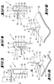
- FIG. 3 to 7 show the interaction of the in Fig. 2 shown and described level indicator 1 with one to be inserted or inserted in the vacuum cleaner Filter bag 35.
- This filter bag 35 is essentially composed made of a cardboard / paper material, multilayer holding plate 36 and one on this attach dust filter bag 37.
- the holding plate 36 For the entry of dust in the dust bag 37 is the holding plate 36 with a Provide opening 38.
- the holding plate 36 has a substantially rectangular one Floor plan, with a longer side 39 and a shorter side 40.
- the longer edge side 39 is assigned an actuating section in the holding plate 36 41 forming, deflectable section 42 formed.
- This operating section 41 is in one Corner area of the holding plate 36, for example in a first Third of the long side 39 formed with a Pivot axis 43, which is the orientation of the shorter Page 40 is aligned accordingly.
- the operating section 41 is shown in FIG Embodiment formed by a layer of the Cardboard / paper material existing holding plate 36, the pivot axis 43 further being perforated, Pre-breaking, compression or the like weakened or provided with an elastic connecting link is, so that a predetermined deformation enables becomes.
- the actuating section 41 from part of the on the holding plate 36 attached dust filter bag 37 to form. Further can also the actuating section from a flexible Membrane exist.
- the filter bag 35 is in the vacuum cleaner too position that the operating section 41 of the Level indicator 1 is aligned facing.
- FIG. 3 schematically shows a situation in which the level indicator 1 in one Home position, d. H. in the non-locking position lingers and a new unused filter bag 35 with one aligned in one plane to the holding plate 36 Operating section 41 moved in the direction of insertion becomes.
- the oversized operating section 41 occurs in the course of the insertion movement of the filter bag 35 against the housing ceiling 24 of the level indicator 1 and will be changed in the course of the further relocation its pivot axis 43 deflected.
- the deflected section 42 lies with its free edge 44 on the outer wall of the Housing 2 below the side wall opening 31.
- the Catch hook 11 can consequently be reached when the maximum Fill level of the filter bag 35 unhindered in the Enter the side wall opening 31 into place.
- the filter bag 35 is in the use position in Overhead position in the, on the vacuum cleaner housing S pivoted filter chamber K held. Due to this protrudes the housing 2, in particular the locking area of the in the vacuum cleaner housing S arranged level indicator 1 over the holding plate 36 of the filter bag 35, further, the operating section 41 therein Position is deflected upwards.
- the level indicator 1 is thus reset in this embodiment when removing the filled filter bag 35.
- the operating section 41 may be as in FIG Fig. 8 shown in a bulge 45 of the holding plate 36 may be arranged so that the holding plate 36 the actuating section 41 in the form of a ring or fork encloses.
- FIG. 9 to 13 show a further embodiment the level indicator 1. This corresponds essentially that of the previously described embodiment. Only The catch hook 11 is also on the top here, d. H. the deflection slope 33 opposite with an upper one Deflection bevel 12 provided. Furthermore, on the Housing 2 on the outside, below the side wall opening 31 a rib 46 is formed, the extension of which in Radial direction of the housing 2 is chosen so that a Cover also in the locking position according to FIG. 9 outwardly projecting catch hook 11 is given.
- the catch hook 11 also acts preferentially here with a deflectable actuating section 41 of Filter bag holding plate 36 together.
- the user gets through the pivoted actuation section 41 is an indication placed on an already used filter bag 35.
- the triggering of the level indicator 1 is in this Embodiment in the course of inserting a new, unused filter bag 35 causes.
- Fig. 14 shows an embodiment of the level indicator 1 according to that in FIGS. 9 to 13 described embodiment in cooperation with the Catch hook 11 with a 45 in a bulge Holding plate 36 arranged actuating section 41 according to the embodiment of the holding plate 36 in FIG. 8.
Abstract
Description
Die Erfindung betrifft zunächst die Anordnung eines Filterbeutels in einem Elektrostaubsauger, wobei der Filterbeutel eine Halteplatte besitzt, die eine Öffnung für den Eintrag von Staub in den Filterbeutel besitzt und einen der Randseite zugeordneten, auslenkbaren Abschnitt aufweist, der im Zuge des Einlegens des Filterbeutels in den Elektrostaubsauger auslenkbar ist, wobei der Elektrostaubsauger eine Füllstandanzeige für den Füllstand des Filterbeutels in dem Elektrostaubsauger aufweist, mit einem Anzeigekolben, wobei der Anzeigekolben durch Druckdifferenz an dem Filterbeutel bewegbar ist und einen Kolbenschaft aufweist mit einem Fanghaken.The invention first relates to the arrangement of a Filter bag in an electric vacuum cleaner, the Filter bag has a holding plate that has an opening for the entry of dust into the filter bag and a deflectable one assigned to the edge side Has section that in the course of inserting the filter bag can be deflected into the electric vacuum cleaner, the electric vacuum cleaner a level indicator for the level of the filter bag in the electric vacuum cleaner has, with an indicator piston, the indicator piston movable by pressure difference on the filter bag is and has a piston skirt with a catch hook.
Im Stand der Technik sind Anordnungen der in Rede stehenden Art bekannt, bei welchen Elektrostaubsauger mit einer Füllstandanzeige oder Saugleistungsanzeige ausgerüstet sind. Eine solche Anzeige indiziert, wann der Filterbeutel seinen maximalen Füllgrad erreicht hat und gegen einen neuen ersetzt werden sollte. Es ist weiterhin bekannt, dass eine solche Füllstandanzeige die Indikation des vollen Filterbeutels auf mechanischem Weg speichert und durch einen Wechsel des Filterbeutels zurückgesetzt wird. Dies geschieht üblicher Weise durch bestimmte Stellelemente an der Halteplatte des Filterbeutels oder durch die Halteplatte selbst, wobei ein Gegenstück, beispielsweise in Form eines Fanghakens, der Füllstandanzeige entriegelt und zurückgesetzt wird. Diesbezüglich wird beispielsweise auf die DE-C2 33 00 250 verwiesen. In the prior art, arrangements of those in question are Kind known in which electric vacuum cleaner with a level indicator or suction power indicator are. Such an indication indicates when the Filter bag has reached its maximum filling level and should be replaced with a new one. It is still known that such a level indicator the Indication of the full filter bag on mechanical Path saves and by changing the filter bag is reset. This is usually done by certain control elements on the holding plate of the filter bag or through the holding plate itself, being a Counterpart, for example in the form of a catch hook, the level indicator is unlocked and reset. In this regard, for example, DE-C2 33 00 250 referenced.
Im Hinblick auf den zuvor beschriebenen Stand der Technik wird eine technische Problematik der Erfindung darin gesehen, eine Anordnung der in Rede stehenden Art in vorteilhafter Weise, insbesondere hinsichtlich der Funktionssicherheit zu verbessern.In view of the prior art described above becomes a technical problem of the invention seen in it an arrangement of the type in question in an advantageous manner, especially with regard to the Improve functional safety.
Diese Problematik ist zunächst und im Wesentlichen
durch den Gegenstand des Anspruches 1 gelöst, wobei
darauf abgestellt ist, dass der Fanghaken an einer
Gehäusewand unter deren Durchdringung verhakbar ist und
dass der als Betätigunsabschnitt ausgebildete, auslenkbare
Abschnitt, der eine freie Randkante aufweist,
durch das nach oben über die Halteplatte vorragende
Gehäuse und/oder den Fanghaken nach oben ausgelenkt
ist. Halteplatten für Filterbeutel werden zumeist mit
hohen Toleranzen gefertigt. Eine große Toleranz in der
Position eines mit der Füllstandanzeige zusammenwirkenden
Betätigungsabschnittes, insbesondere in Verbindung
mit eine Toleranz die bei der Fertigung der Halteplattenhalterung
im Gerät berücksichtigt werden muss, kann
im ungünstigen Fall dazu führen, dass ein passgenaues
Zusammenspiel von Betätigungsabschnitt und Füllstandanzeige
nicht möglich ist. Zufolge der erfindungsgemäßen
Ausgestaltung ist ein Stellelement in Form eines auslenkbaren
Betätigungsabschnittes angegeben, welches
über einen ausreichenden Toleranzausgleich verfügt, so
dass eine Zusammenwirkung mit der Füllstandanzeige bzw.
dessen Fanghaken auch bei einer ungünstigen Paarung der
Toleranzen von Halteplatte und Halteplattehalterung im
Gerät möglich ist. Der Betätigungsabschnitt ist einer
Randseite des Filterbeutels bzw. dessen Halteplatte
zugeordnet angeordnet, wobei der Betätigungsabschnitt
zur Randkante der Halteplatte frei geschnitten oder in
einer Ausbuchtung der Halteplatte angeordnet ist. Bei
Anordnung des Betätigungsabschnittes im Bereich einer
Ausbuchtung der Halteplatte ist dieser ring- oder gabelförmig
umschlossen. Dadurch bedingt, dass der Betätigungsabschnitt
mit einem bestimmten Übermaß gefertigt
ist, ist ein Zusammenspiel mit der Füllstandanzeige
auch bei ungünstiger Toleranzpaarung möglich. Das Übermaß
des Betätigungsabschnittes verursacht im Zuge eines
Einsetzens des Filterbeutels in die Filterkammer eine
Verformung des Betätigungsabschnittes, wonach letzterer
mit seiner freien, bevorzugt im Wesentlichen parallel
zur Lenkachse verlaufenden Randkante nach oben ausgelenkt
wird. Dies bedingt durch eine Kollision mit dem
nach oben über die Halteplatte vorragenden Gehäuse
und/oder dem Fanghaken. Als weiterhin vorteilhaft erweist
es sich durch die erfindungsgemäße Ausgestaltung,
dass durch die Auslenkung des Betätigungsabschnittes im
Zuge des Einsetzens des Filterbeutels über den ausgelenkten
Betätigungsäbschnitt dem Benutzer eine Anzeige
gegeben wird, dass dieser Filterbeutel bereits einmal
genutzt wurde. Um den Betätigungsabschnitt eines neuen,
ungebrauchten Filterbeutels gegen unbeabsichtigte Beschädigung,
beispielsweise beim Transport, zu schützen,
kann der Betätigungsabschnitt - wie bereits erwähnt -
ring- oder gabelförmig umschlossen sein. Darüber hinaus
ist es auch denkbar, dem Betätigungsabschnitt erst
durch Aufreißen einer perforierten Zone auszubilden,
welches Aufreißen im Zuge der Einsetzbewegung des Filterbeutels
in die Filterkammer automatisch durch Beaufschlagung
des in dem Einschubweg des Betätigunsabschnittes
angeordneten Füllstandanzeige-Gehäuses. In einer
weiteren Ausgestaltung des Erfindungsgegenstandes ist
vorgesehen, dass der Betätigungsabschnitt durch ein
Gehäuseabschnitt, der sich in Überdeckung zu dem Fanghaken
unterhalb des Fanghakens erstreckt, ausgelenkt ist.
Dieser Gehäuseabschnitt kann in Form einer von dem
Füllstandanzeige-Gehäuse abragenden Rippe gebildet
sein, gegen deren Oberkante der Betätigungsabschnitt
des Filterbeutels im Zuge des Einsetzens desselben bzw.
im Zuge einer Verlagerung des Filterbeutels in eine
Betriebsstellung ausgelenkt wird. In einer vorteilhaften
Anordnung ist vorgesehen, dass der Fanghaken an
einer Seitenwand des Gehäuses unterhalb einer Gehäusedecke,
welche Seitenwand eine diesbezügliche Öffnung
aufweist, unter Durchsetzung der Seitenwand verhakbar
ist. Der mit dem nach oben ausgelenkten Betätigungsabschnitt
eingesetzte Filterbeutel beaufschlagt mit diesem
Betätigungsabschnitt im Zuge einer Herausnahme des
Filterbeutels den, bei maximalem Füllstand durch die
Gehäuseöffnung getretenen und dort verrastenden Fanghaken
derart, dass dieser durch die Öffnung zurück in das
Gehäuse verlagert wird, zur Einleitung einer Rückstellung
in die Füllstandanzeige-Grundstellung. Bevorzugt
weist hierzu der Fanghaken eine nach unten, d. h. in
Richtung auf den nach oben ausgelenkten Betätigungsabschnitt
weisende Auslenkschräge auf. Zufolge dessen
erfolgt die Rückstellung der Füllstandanzeige bei einem
Herausnehmen des gefüllten Filterbeutels. Alternativ
kann die Rückstellung auch im Zuge des Einsetzens eines
bevorzugt neuen, ungebrauchten Filterbeutels erfolgen.
Hierbei wird der, zunächst bevorzugt in einer Ebene zur
Halteplatte des Filterbeutels ausgerichtete Betätigungsabschnitt
durch Beaufschlagung durch das Füllstandanzeige-Gehäuse
ausgelenkt, worauf hin dieser im Zuge der
weiteren Einwärtsverlagerung des Filterbeutels den
durch die Gehäuseöffnung getretenen Fanghaken beaufschlagt.
Letzterer wird hierdurch bedingt durch die
Gehäuseöffnung zurückverlagert. In der Betriebsstellung
des Filterbeutels verbleibt der Betätigungsabschnitt
durch Anlage an dem Gehäuseabschnitt, beispielsweise
der Rippe, in der ausgelenkten Stellung, bevorzugt in
einer um ca. 90° zur Halteplattenerstrekkung
gerichteten Stellung. Der Gehäuseabschnitt bzw.
die Rippe dient im Zuge der Herausnahme des gefüllten
Filterbeutels dem Vorbeiführen des abgelenkten Betätigungsabschnittes
an dem, durch die Gehäuseöffnung getretenen
Fanghaken. Letztere wird somit im Zuge der Auswärtsbewegung
des Filterbeutels nicht beaufschlagt.
Bevorzugt wird weiter, dass der Betätigungsabschnitt in
der Betriebsstellung unterhalb der Gehäusedecke endet.
Insbesondere ist vorgesehen, dass die freie Randkante
in dieser Betriebsstellung unterhalb der Gehäusdecke endet,
wobei diese freie Randkante die der Schwenkachse
des Betätigungsabschnittes gegenüberliegende, den Fanghanken
zur Rückstellung desselben zu beaufschlagende
Randkante ist. Auch wird vorgeschlagen, dass die freie
Randkante in der Betriebsstellung unterhalb des Fanghakens
endet. In einer vorteilhaften Weiterbildung ist
vorgesehen, dass die Halteplatte einen rechteckigen
Grundriss aufweist, mit einer längeren und einer kürzeren
Seite und dass der Betätigungsabschnitt um eine der
Ausrichtung der kürzeren Seite entsprechenden Achse
veschwenkt ist. Diesbezüglich wird weiter vorgeschlagen,
dass der Betätigunsabschnitt einem Eckbereich der
Halteplatte zugeordnet ist, so weiter bevorzugt in
einem - in Längserstreckung der Halteplatte - ersten
Drittel der Längsrandseite der Halteplatte. Bezüglich
der Ausgestaltung des Betätigunsabschnittes wird vorgeschlagen,
dass dieser Teil der Halteplatte ist. So ist
bevorzugt vorgesehen, dass der Betätigungsabschnitt aus
dem Pappe-/Papierwerkstoff der Halteplatte besteht.
Eine aus Pappe-/Papierwerkstoff bestehende Halteplatte
besteht in der Regel aus mehreren, so beispielsweise
aus drei oder vier Lagen. Um hier einen auslenkbaren
Betätigungsabschnitt auszubilden, kann dieser beispielsweise
lediglich über eine Lage ausgebildet sein. Darüber
hinaus ist es denkbar, den Betätigungsabschnitt
durch Perforation, Vorbruch oder Verdichtung im Bereich
der Halteplatte auszubilden, so dass eine vorbestimmte
Verformung ermöglicht wird. Des Weiteren ist auch denkbar,
den Betätigungsabschnitt über ein elastisches
Verbindungsglied mit der Halteplatte zu verbinden.
Zudem ist denkbar, dass bei einer Halteplatte, an welchem
ein Staubfilterbeutel befestigt ist, der Betätigungsabschnitt
aus einem Teil des Staubfilterbeutels
gebildet ist, so beispielsweise in einem, im Befestigungsbereich
der Halteplatte gefalteten und somit
leicht ausgesteiftem Bereich des Staubfilterbeutels.
Schließlich ist es auch denkbar, dass der Betätigungsabschnitt
aus einer flexiblen Membran besteht.This problem is solved first and foremost by the subject matter of
A holding plate made of cardboard / paper material usually consists of several, for example three or four layers. In order to form a deflectable actuating section here, it can be formed, for example, only over one layer. In addition, it is conceivable to form the actuating section by perforation, pre-break or compression in the area of the holding plate, so that a predetermined deformation is made possible. Furthermore, it is also conceivable to connect the actuating section to the holding plate via an elastic connecting member. It is also conceivable that, in the case of a holding plate to which a dust filter bag is attached, the actuating section is formed from a part of the dust filter bag, for example in an area of the dust filter bag which is folded in the fastening area of the holding plate and is therefore slightly stiffened. Finally, it is also conceivable that the actuating section consists of a flexible membrane.
Die Erfindung betrifft des Weiteren ein Filterbeutel mit einer Halteplatte, welche Halteplatte einem der Randseite zugeordneten, auslenkbaren Abschnitt aufweist. Um einen Filterbeutel mit einer Halteplatte der in Rede stehenden Art in vorteilhafter Weise weiterzubilden, wird vorgeschlagen, dass der randseitige Abschnitt als Betätigungsabschnitt ausgebildet ist. Letzterer dient bevorzugt zur Zusammwirkung mit einer Füllstandanzeige in einem, den Filterbeutel aufnehmenden Gehäuse eines Elektrostaubsaugers. Hierbei kann der Betätigungsabschnitt zum Rand des Filterbeutels hin frei ausgebildet sein. Es ist jedoch auch denkbar, den Betätigungsabschnitt mit einem geringen Abstand zum Rand des Filterbeutels anzuordnen, so beispielsweise in einem randseitigen, ring- oder gabelförmig umschlossenen Bereich des Filterbeutels. In einer vorteilhaften Weiterbildung ist vorgesehen, dass der Betätigungsabschnitt auslenkbar ist. Zudem wird vorgeschlagen, dass die Halteplatte einen rechteckigen Grundriss aufweist, mit einer längeren und einer kürzeren Seite und dass der Betätigungsabschnitt um eine der Ausrichtung der kürzeren Seite entsprechenden Achse verschwenkbar ist. Auch ist in einer bevorzugten Ausgestaltung vorgesehen, dass der Betätigungsabschnitt einem Eckbereich der Halteplatte zugeordnet ist, so weiter bevorzugt in einem - in Längserstreckung der Halteplatte betrachteten - ersten Drittel der Längsrandseite der Halteplatte. Als besonders vorteilhaft erweist es sich, dass der Betätigungsabschnitt Teil der Halteplatte ist, wobei diesbezüglich weiter vorgeschlagen wird, dass der Betätigungsabschnitt aus dem Pappe-/Papierwerkstoff der Halteplatte besteht. Halteplatten aus Pappe-/Papierwerkstoff bestehen in der Regel aus mehreren, beispielsweise aus drei oder vier Lagen. Der auslenkbare Betätigungsabschnitt ist hierbei bevorzugt gebildet aus einer Lage der Halteplatte, wodurch eine vorbestimmte Verschwenkachse im Übergangsbereich von dem einlagigen Betätigungsabschnitt zu der mehrlagigen Halteplatte vorbestimmt ist. Die Auslenkbarkeit des Betätigungsabschnittes kann auch durch Perforation, Vorbruch oder Verdichtung des Pappe-/Papierwerkstoffes erreicht sein. Darüber hinaus ist es auch denkbar, ein elastisches Verbindungsglied zwischen Betätigungsabschnitt und Halteplatte vorzusehen. Weiter wird bei einer Halteplatte mit einem hieran befestigten Staubfilterbeutel vorgeschlagen, dass der Betätigungsabschnitt aus einem Teil des Staubfilterbeutels gebildet ist. So kann beispielsweise der Betätigungsabschnitt im Bereich eines durch Faltung verstärkten Abschnittes des Staubfilterbeutels ausgebildet sein. Schließlich wird vorgeschlagen, dass der Betätigungsabschnitt aus einer flexiblen Membran besteht.The invention further relates to a filter bag with a holding plate, which holding plate one of the Has edge-associated, deflectable section. To a filter bag with a holding plate to further develop the type in question in an advantageous manner, it is suggested that the edge section is designed as an actuating section. The latter is preferably used to interact with a level indicator in one that holds the filter bag Housing of an electric vacuum cleaner. Here, the Actuating section towards the edge of the filter bag be freely trained. However, it is also conceivable that Actuating section with a short distance to Arrange the edge of the filter bag, for example in an edge-side, ring-shaped or fork-shaped Area of the filter bag. In an advantageous Training is provided that the operating section is deflectable. It is also proposed that the holding plate has a rectangular plan, with a longer and a shorter side and that the actuating section by one of the orientation of the shorter side corresponding axis is pivotable. In a preferred embodiment, that the operating section a corner area of the Holding plate is assigned, so further preferred in one - viewed in the longitudinal extent of the holding plate - First third of the longitudinal edge side of the holding plate. It proves to be particularly advantageous that the Actuating section is part of the holding plate, wherein in this regard, it is further proposed that the operating section made of cardboard / paper material Holding plate is there. Holding plates made of cardboard / paper material usually consist of several, for example from three or four layers. The deflectable operating section is preferably formed from a Position of the holding plate, whereby a predetermined pivot axis in the transition area from the single layer Actuating section to the multi-layer holding plate is predetermined. The deflectability of the actuating section can also be caused by perforation, pre-opening or Compression of the cardboard / paper material has been reached. In addition, it is also conceivable to use an elastic one Link between the operating section and To provide a holding plate. Next is a holding plate proposed with a dust filter bag attached to it, that the operating section from one part of the dust filter bag is formed. For example the operating section in the area of a through Folding reinforced section of the dust filter bag be trained. Finally, it is suggested that the actuating section made of a flexible membrane consists.
Nachstehend ist die Erfindung anhand der beigefügten Zeichnungen, welche lediglich mehrere Ausführungsbeispiele darstellen, näher erläutert. Es zeigt:
- Fig. 1
- eine perspektivische Darstellung eines Elektrostaubsaugers, mit einer Filterkammer und einer Füllstandanzeige;
- Fig. 2
- eine schematische Schnittdarstellung durch eine Füllstandanzeige in einer ersten Ausführungsform, die, den maximalen Füllstand eines Filterbeutels anzeigende Raststellung betreffend;
- Fig. 3
- eine geschnittene Detaildarstellung des Rastbereiches der Füllstandanzeige gemäß Fig. 2, die gelöste Stellung eines Fanghakens bei entnommenen Filterbeutel betreffend;
- Fig. 4
- eine der Fig. 3 entsprechende Darstellung, jedoch bei eingelegtem Filterbeutel und nach einem Verrasten des Fanghakens am Anzeigengehäuse;
- Fig. 5
- eine weitere der Fig. 3 entsprechende Darstellung, bei Beaufschlagung des Rasthakens im Zuge einer Filterbeutelentnahme;
- Fig. 6
- eine perspektivische Darstellung des Rastbereiches der Füllstandanzeige mit zugeordneter Filterbeutel-Halteplatte, die Stellung gemäß Fig. 4 betreffend;
- Fig. 7
- eine weitere perspektivische Darstellung, die Ausführungsform und Stellung gemäß Fig. 6 betreffend;
- Fig. 8
- eine der Fig. 6 entsprechende Darstellung mit einer Filterbeutel-Halteplatte in einer weiteren Ausführungsform;
- Fig. 9
- eine der Fig. 3 entsprechende Detaildarstellung, mit einer Füllstandanzeige in einer weiteren Ausführungsform, die verrastete Stellung des Fanghakens bei entnommenen Filterbeutel betreffend;
- Fig. 10
- eine der Fig. 9 entsprechende Darstellung, bei Beaufschlagung des Rasthakens im Zuge eines Einsetzen des Filterbeutels;
- Fig. 11
- eine der Fig. 3 entsprechende Darstellung, jedoch die Ausführungsform gemäß Fig. 9 betreffend;
- Fig. 12
- eine weitere Darstellung gemäß Fig. 9, im Zuge einer Herausverlagerung des Filterbeutels;
- Fig. 13
- eine der Fig. 6 entsprechende perspektivische Darstellung, die Stellung der weiteren Ausführungsform gemäß Fig. 11 betreffend;
- Fig. 14
- eine perspektivische Darstellung gemäß Fig. 13 mit einer Filterbeutel-Halteplatte gemäß der in Fig. 8 dargestellten Form.
- Fig. 1
- a perspective view of an electric vacuum cleaner, with a filter chamber and a level indicator;
- Fig. 2
- is a schematic sectional view through a fill level indicator in a first embodiment, the locking position indicating the maximum fill level of a filter bag;
- Fig. 3
- a detailed sectional view of the locking area of the level indicator according to Figure 2, the released position of a catch hook with the filter bag removed.
- Fig. 4
- a representation corresponding to Figure 3, but with an inserted filter bag and after locking the catch hook on the display housing.
- Fig. 5
- another representation corresponding to FIG 3, when the latching hook is acted upon in the course of a filter bag removal;
- Fig. 6
- a perspective view of the locking area of the level indicator with an associated filter bag holding plate, the position according to FIG. 4;
- Fig. 7
- a further perspective view, regarding the embodiment and position according to FIG. 6;
- Fig. 8
- 6 shows a representation corresponding to FIG. 6 with a filter bag holding plate in a further embodiment;
- Fig. 9
- a detail representation corresponding to FIG. 3, with a fill level indicator in a further embodiment, relating to the latched position of the catch hook when the filter bag is removed;
- Fig. 10
- 9 shows a representation corresponding to FIG. 9 when the latching hook is acted upon by inserting the filter bag;
- Fig. 11
- a representation corresponding to FIG. 3, but relating to the embodiment according to FIG. 9;
- Fig. 12
- a further illustration according to FIG 9, in the course of moving the filter bag out;
- Fig. 13
- 6 shows a perspective illustration corresponding to the position of the further embodiment according to FIG. 11;
- Fig. 14
- a perspective view of FIG. 13 with a filter bag holding plate according to the shape shown in Fig. 8.
Dargestellt und beschrieben ist zunächst mit Bezug zu
den Fig. 1 ein Elektrostaubsauger mit einem Staubsaugergehäuse
S und einer einen Filterbeutel 35 mit einer
Halteplatte 36 aufnehmenden Filterkammer K. In dem
Staubsaugergehäuse S ist zugeordnet dem Filterbeutel 35
eine Füllstandanzeige 1 für den Füllstand des Filterbeutels
35 angeordnet.Is shown and described initially with reference to
1 shows an electric vacuum cleaner with a vacuum cleaner housing
S and a
Die Füllstandanzeige 1 weist in einem, ggf. transparenten
Gehäuse 2 einen Anzeigekolben 3 auf, welch Letzterer
als Membrankolben 4 ausgebildet ist. Konkret ist
die Ausgestaltung so gewählt, dass der Membrankolben 4
sich zusammensetzt aus dem, beispielsweise aus Hartkunststoff
gebildeten Anzeigekolben 3 und einer dichtend
an der Außenwandung des Anzeigekolben 3 befestigten,
schlauchförmigen und elastischen Weichmembran 5.The
Die Weichmembran 5 ist im Bereich eines in dem Gehäuse
2 angeordneten Zwischenbodens 6 dichtend gehaltert. An
der, dem Zwischenboden 6 zugewandten Unterseite des im
Wesentlichen einen kreisrunden Querschnitt aufweisenden
Anzeigekolbens 3 ist zentral ein Kolbenschaft 7 angeformt.
Letzterer durchsetzt den Zwischenboden 6 im
Bereich einer zentralen Durchbrechung 8, welche zur
kreislinienartigen Führung des Kolbenschaftes 7 als
Pendellagerstelle ausgebildet ist.The
Das dem Anzeigekolben 3 abgewandte freie Ende des Kolbenschaftes
7 ist mit einem Radialkragen 9 versehen,
gegen welchen sich eine, den Kolbenschaft 7 umfassende
Druckfeder 10 einerends abstützt. Das andere Ende der
Druckfeder 10 tritt im Bereich der Pendellagerstelle
bzw. Durchbrechung 8 unterseitig gegen den Zwischenboden
6, womit die Druckfeder 10 die Funktion einer Rückstellfeder
für den Anzeigekolben 3 übernimmt.The free end of the piston shaft facing away from the
Der Kolbenschaft 7 ist über den Anzeigekolben hinaus
verlängert zur Bildung eines Fanghakenschaftes 30.
Letzterer verläuft gegenüber der Kolbenschaftachse
leicht geneigt. The piston shaft 7 is beyond the indicator piston
extended to form a
Das Gehäuse 2 ist im Bereich des Fanghakenschaftes 30
gegenüber dem, den Membrankolben 4 umschließenden Bereich
querschnittsverjüngt, wobei dieser querschnittsverjüngte
Bereich durch eine Gehäusedecke 24 geschlossen
ist.The
Der am freien Ende des Fanghakenschaftes 30 angeordnete
Fanghaken 11 durchsetzt in der Raststellung gemäß Fig.
8, welche Raststellung den maximalen Füllgrat des Filterbeutels
darstellt, eine unterhalb der Decke 24 angeordnete
Öffnung 31 der Gehäuseseitenwand 32. Der Fanghaken
11 ist in diese Stellung aufgrund der zentrierenden
Wirkung der Membran 5 vorgespannt.The one arranged at the free end of the
Des Weiteren weist der Fanghaken 11 eine nach unten
weisende Auslenkschräge 33 auf, welche in Richtung auf
den Fanghakenschaft 30 in eine Abflachung 34 übergeht.
Diese Abflachung 34 ist in ihrer Tiefe so gewählt, dass
bei Anlage des Fanghakenschaftes 30 innenwandig des
Gehäuses 2 die Fußlinie der anschließenden Auslenkschräge
33 in Überdeckung liegt mit einer äußeren Randkante
der Gehäuseöffnung 31.Furthermore, the
Der Auslenkschrägen 33 gegenüberliegend ist der Fanghaken
11 abgeflacht, bevorzugt etwa parallel zur Ausrichtung
der Decke 24 verlaufend ausgebildet.The catch hook is opposite the deflecting
Durch den dichtend in dem Gehäuse 2 gehalterten Membrankolben
4 sind zwei Druckkammern 13 und 14 im Gehäuse 2
gebildet. Die oberhalb des Membrankolbens 4, dem Fanghaken
11 zugewandt ausgebildete Druckkammer 14 steht über
eine im Bereich der Gehäusestufe ausgeformte Gehäuseöffnung
15 in Verbindung mit dem Filterbeuteläußeren.
Demnach entspricht das Druckpotenzial in der Druckkammer
14 dem des in Luftströmungsrichtung hinter dem
Filterbeutel gemessenen Druckpotenzials.Through the membrane piston, which is sealed in the
Die der Unterseite der Weichmembran 5 zugeordnete Druckkammer
13 steht über eine, nicht dargestellte gehäusebodenseitige
Öffnung mit dem Filterbeutelinneren in Verbindung,
womit das Druckpotenzial in der Druckkammer 13
dem Druckpotenzial im Innern des Filterbeutels entspricht.The pressure chamber assigned to the underside of the
Die Funktion der Füllstandanzeige ist wie folgt:The function of the level indicator is as follows:
Im Betrieb des nicht dargestellten Staubsaugers verändern
sich die Druckpotenziale in den Druckkammern 13,
14 des Gehäuses 2. Ausgehend von einer Ruhestellung
wird ein Ansteigen des Druckpotenzials in der Druckkammer
13 bei gleich bleibendem Druckpotenzial in der
Druckkammer 14 angenommen. Der in der Druckkammer 13
vorherrschende Druck steht, bedingt durch in dem Zwischenboden
6 vorgesehene Durchbrechung 17, an der Innenseite
der Weichmembran 5 an. Durch das gegenüber dem
Druckpotenzial in der Druckkammer 14 ansteigende Druckpotenzial
in der Kammer 13 wird der Anzeigekolben 3 in
Achsrichtung desselben bewegt, dies bedingt durch eine
Druckluftaufblähung der in der Ruhestellung übergefalteten
Weichmembran 5.Change in the operation of the vacuum cleaner, not shown
the pressure potential in the
Die Verschiebung des Anzeigekolbens 3 erfolgt in Abhängigkeit
von den Druckunterschieden so lange bis der
Fanghaken 11 mit seiner Auslenkschrägen 12 in die Öffnung
31 tritt und dort verhakt.The displacement of the
Die Vertikalverlagerung des Anzeigekolbens geschieht
gegen die Federkraft der Rückstellfeder 10, deren Federkraft
angepasst ist an die üblichen Druckpotenziale in
dem Gehäuse 2.The indicator piston is displaced vertically
against the spring force of the
In der verrasteten Stellung gemäß Fig. 2 zeigt die
Füllstandanzeige 1 die maximal zulässige Befüllung des
Staubfilterbeutels an. Über den festgelegten Fanghaken
11 kann beispielsweise über mechanischem Wege ein Ausschalten
des Staubsaugers bewirkt werden. Ist der maximale
Füllstand in dem Filterbeutel nicht erreicht, so
gelangt der Anzeigekolben 3 nicht in die diesen verrastende
Stellung, was nach einem Abschalten des Staubsaugers
eine durch die Druckfeder 10 hervorgerufene Rückstellung
des Anzeigekolbens 3 und eine damit einhergehende
Überfaltelung der Membran 5 in die Ruhestellung
zur Folge hat.2 shows the
Bei einer transparenten Ausgestaltung des Gehäuses 2
kann der Füllstand des Staubfiltersbeutels mittels des
Anzeigekolbens 3 dargestellt werden. Es ist jedoch auch
möglich, an beliebiger Stelle des Anzeigekolbens 3 oder
auch des Kolbenschaftes 7 ein Bauteil zur Visualisierung
der Stellposition anzuordnen.With a transparent configuration of the
Die Verhakungsstellung gemäß Fig. 2 ist nur durch gesonderten
Eingriff aufhebbar, so beispielsweise durch
Auslenkung des Fanghakens 11 in Richtung des Gehäuseinneren.
Diese beispielsweise horizontal wirkende Kraft
kann durch Einlegen eines neuen Filterbeutels aufgebracht
werden.2 is only by separate
Intervention can be canceled, for example by
Deflection of the
Nach einer entsprechenden seitlichen Auslenkung des
Fanghakens 11 bewirkt die gespannte Druckfeder 10 die
Rückstellung des Membrankolbens 4 in die übergefaltete
Ruhestellung. After a corresponding lateral deflection of the
Die Fig. 3 bis 7 zeigen die Zusammenwirkung der in Fig.
2 dargestellt und beschriebenen Füllstandanzeige 1 mit
einem in dem Staubsauger einzulegenden bzw. eingelegten
Filterbeutel 35.3 to 7 show the interaction of the in Fig.
2 shown and described
Dieser Filterbeutel 35 setzt sich im Wesentlichen zusammen
aus einer, aus einem Pappe-/Papierwerkstoff bestehenden,
mehrlagigen Halteplatte 36 und einem an diesem
befestigen Staubfilterbeutel 37. Zum Eintrag von Staub
in dem Staubbeutel 37 ist die Halteplatte 36 mit einer
Öffnung 38 versehen.This
Die Halteplatte 36 besitzt einen im Wesentlichen rechteckigen
Grundriss, mit einer längeren Seite 39 und
einer kürzeren Seite 40. Der längeren Randseite 39
zugeordnet ist in der Halteplatte 36 ein, einen Betätigungsabschnitt
41 bildender, auslenkbarer Abschnitt 42
ausgeformt. Dieser Betätigungsabschnitt 41 ist in einem
Eckbereich der Halteplatte 36, etwa in einem ersten
Drittel der Längsseite 39 ausgebildet, mit einer
Schwenkachse 43, welche der Ausrichtung der kürzeren
Seite 40 entsprechend ausgerichtet ist.The holding
Der Betätigungsabschnitt 41 ist in dem dargestellten
Ausführungsbeispiel gebildet durch eine Lage der aus
Pappe-/Papierwerkstoff bestehenden Halteplatte 36,
wobei die Schwenkachse 43 des Weiteren durch Perforation,
Vorbruch, Verdichtung oder ähnlichem geschwächt
oder mit einem elastischen Verbindungsglied versehen
ist, so dass eine vorbestimmte Verformung ermöglicht
wird. Darüber hinaus ist es auch denkbar, den Betätigungsabschnitt
41 aus einem Teil des an der Halteplatte
36 befestigten Staubfilterbeutels 37 zu bilden. Weiter
kann auch der Betätigungsabschnitt aus einer flexiblen
Membran bestehen. The operating
Der Filterbeutel 35 ist in dem Staubsauger derart zu
positionieren, dass der Betätigungsabschnitt 41 der
Füllstandanzeige 1 zugewandt ausgerichtet ist.The
In der Fig. 3 ist schematisch eine Situation dargestellt,
bei welcher die Füllstandanzeige 1 in einer
Grundstellung, d. h. in der nicht verrastenden Stellung
verweilt und ein neuer ungebrauchter Filterbeutel 35
mit einem, in einer Ebene zur Halteplatte 36 ausgerichteten
Betätigungsabschnitt 41 in Einsetzrichtung bewegt
wird.3 schematically shows a situation
in which the
Der mit einem Übermaß versehene Betätigungsabschnitt 41
tritt im Zuge der Einsetzbewegung des Filterbeutels 35
gegen die Gehäusedecke 24 der Füllstandanzeige 1 und
wird im Zuge der weiteren Einsetzverlagerung hierbei um
seine Schwenkachse 43 ausgelenkt.The
In Fig. 4 ist die Betriebsstellung des Filterbeutels 35
dargestellt. Der ausgelenkte Abschnitt 42 liegt mit
seiner freien Randkante 44 an der Außenwandung des
Gehäuses 2 unterhalb der Seitenwand-Öffnung 31 an. Der
Fanghaken 11 kann demzufolge bei Erreichen des maximalen
Füllstandes des Filterbeutels 35 ungehindert in die
Seitenwand-Öffnung 31 verrastend eintreten.4 is the operating position of the
Der Filterbeutel 35 ist in der Benutzungsstellung in
Überkopflage in der, auf das Staubsaugergehäuse S
schwenkbaren Filterkammer K gehalten. Hierdurch bedingt
ragt das Gehäuse 2, insbesondere der Rastbereich der in
dem Staubsaugergehäuse S angeordneten Füllstandanzeige
1 über die Halteplatte 36 des Filterbeutels 35 vor,
wobei weiter der Betätigungsabschnitt 41 in dieser
Stellung nach oben ausgelenkt ist. The
Bei einer Aufwärtsverlagerung des Filterbeutels 35 zur
Entnahme desselben wird die nach unten weisende Auslenkschräge
33 des Fanghakens 11 durch den nach oben weisenden
Betätigungsabschnitt 41 der Halteplatte 36 bzw. des
Filterbeutels 35 beaufschlagt, wodurch der Fanghaken 11
aus der Öffnung 31 heraus in das Gehäuseinnere bewegt
wird, zur Aufhebung der Verrastung. Hiernach wird der
Fanghaken und der Membrankolben aufgrund der Federbelastung
des Kolbenschaftes wieder in die Ruhestellung
zurückverlagert.With an upward displacement of the
Eine Rückstellung der Füllstandanzeige 1 erfolgt somit
in diesem Ausführungsbeispiel bei der Entnahme des
gefüllten Filterbeutels 35.The
Durch den ausgelenkten Abschnitt 42 ist dem Benutzer
ein Hinweis gegeben, dass dieser Filterbeutel bereits
genutzt wurde.Through the deflected
Alternativ kann der Betätigungsabschnitt 41 wie in der
Fig. 8 dargestellt in einer Ausbuchtung 45 der Halteplatte
36 angeordnet sein, so dass die Halteplatte 36
den Betätigungsabschnitt 41 ring- bzw. gabelförmig
umschließt.Alternatively, the operating
Die Fig. 9 bis 13 zeigen eine weitere Ausführungsform
der Füllstandanzeige 1. Diese entspricht im Wesentlichen
der der zuvor beschriebenen Ausführungsform. Lediglich
der Fanghaken 11 ist hier auch oberseitig, d. h.
der Auslenkschräge 33 gegenüberliegend mit einer oberen
Auslenkschräge 12 versehen. Des Weiteren ist an dem
Gehäuse 2 außenseitig, unterhalb der Seitenwandöffnung
31 eine Rippe 46 ausgebildet, deren Erstreckung in
Radialrichtung des Gehäuses 2 so gewählt ist, dass eine
Überdeckung zudem in der Raststellung gemäß der Fig. 9
nach außen ragenden Fanghaken 11 gegeben ist.9 to 13 show a further embodiment
the
Wie dargestellt wirkt auch hier der Fanghaken 11 bevorzugt
mit einem auslenkbaren Betätigungsabschnitt 41 der
Filterbeutel-Halteplatte 36 zusammen.As shown, the
Bei einem Einlegen eines neuen, ungebrauchten Filterbeutels
mit einem in Ebenenerstreckung der Halteplatte 36
ausgerichteten Betätigungsabschnitt 41 wird letzterer
aufgrund der gewählten Überlänge bei Auftreffen auf die
Decke 24 des Gehäuses 2 ausgelenkt und hiernach über
die obere Auslenkschräge 12 des Fanghakens 11 bewegt.
Hierbei bewirkt der Betätigungsabschnitt 41 eine Rückverlagerung
des Fanghakens 11 aus der Seitenwand-Öffnung
31 hinaus, zur Rückstellung der Füllstandanzeige 1
(vgl. Fig. 10).When inserting a new, unused filter bag
with a plane extension of the holding
In der Betriebsstellung gemäß Fig. 11 liegt der ausgelenkte
Betätigungsabschnitt 41 an der gehäuseseitigen
Rippe 46 an und ist hierbei - wie dargestellt - bevorzugt
um 90° nach oben abgeschwenkt. Durch die Abstützung
an der Rippe 46 wird diese abgeschwenkte Stellung
des Betätigungsabschnittes 41 auch dann beibehalten,
wenn eine Aufwärtsverlagerung des Filterbeutels 35 zur
Entnahme desselben erfolgt, so dass der Betätigungsabschnitt
41 - wie in Fig 12 dargestellt - an dem bei
maximalen Füllstand des Staubbeutels 37 verrasteten
Fanghaken 11, nicht mit diesem zusammenwirkend, vorbeiläuft.11 is the deflected
Auch in dieser Ausführungsform wird dem Benutzer durch
den abgeschwenkten Betätigungsabschnitt 41 ein Hinweis
auf einen bereits gebrauchten Filterbeutel 35 gegeben. In this embodiment, too, the user gets through
the pivoted
Die Auslösung der Füllstandanzeige 1 wird in dieser
Ausführungsform im Zuge des Einlegens eines neuen,
ungebrauchten Filterbeutels 35 bewirkt.The triggering of the
Schließlich zeigt Fig. 14 eine Ausführung der Füllstandanzeige
1 gemäß der bezüglich der in den Fig. 9 bis 13
beschriebenen Ausführungsform unter Zusammenwirkung des
Fanghakens 11 mit einem in einer Ausbuchtung 45 der
Halteplatte 36 angeordneten Betätigungsabschnitt 41
gemäß der Ausführungsform der Halteplatte 36 in Fig. 8.Finally, Fig. 14 shows an embodiment of the
Alle offenbarten Merkmale der Erfindung sind (für sich) erfindungswesentlich. In die Offenbarung der Anmeldung wird hiermit auch der Offenbarungsinhalt der zugehörigen/beigefügten Prioritätsunterlagen (Abschrift der Voranmeldung) vollinhaltlich mit einbezogen, auch zu dem Zweck, Merkmale dieser Unterlagen in Ansprüche vorliegender Anmeldung mit aufzunehmen.All disclosed features of the invention are (in themselves) essential to the invention. In the disclosure of the application is also the disclosure content of the associated / attached Priority documents (copy of the Pre-registration) fully included, also to the purpose, features of these documents in claims including this application.
Claims (20)
Priority Applications (2)
| Application Number | Priority Date | Filing Date | Title |
|---|---|---|---|
| DE20122118U DE20122118U1 (en) | 2000-07-20 | 2001-07-13 | Arrangement of filter bag for electric vacuum cleaner has catch hook hooked on housing wall below penetration and section that can be deflected is deflected upwards by housing |
| SI200130621T SI1174072T1 (en) | 2000-07-20 | 2001-07-13 | Filter bag arrangement in electric vacuum cleaners and filter bag with holding plate |
Applications Claiming Priority (2)
| Application Number | Priority Date | Filing Date | Title |
|---|---|---|---|
| DE10051304A DE10051304A1 (en) | 2000-07-20 | 2000-07-20 | Arrangement of a filter bag in an electric vacuum cleaner and filter bag with a holding plate |
| DE10051304 | 2000-07-20 |
Publications (3)
| Publication Number | Publication Date |
|---|---|
| EP1174072A2 true EP1174072A2 (en) | 2002-01-23 |
| EP1174072A3 EP1174072A3 (en) | 2002-12-11 |
| EP1174072B1 EP1174072B1 (en) | 2006-06-07 |
Family
ID=7660008
Family Applications (1)
| Application Number | Title | Priority Date | Filing Date |
|---|---|---|---|
| EP01116652A Expired - Lifetime EP1174072B1 (en) | 2000-07-20 | 2001-07-13 | Filter bag arrangement in electric vacuum cleaners and filter bag with holding plate |
Country Status (5)
| Country | Link |
|---|---|
| EP (1) | EP1174072B1 (en) |
| AT (1) | ATE328524T1 (en) |
| DE (2) | DE10051304A1 (en) |
| ES (1) | ES2262581T3 (en) |
| HK (1) | HK1044104A1 (en) |
Cited By (1)
| Publication number | Priority date | Publication date | Assignee | Title |
|---|---|---|---|---|
| EP1639933A2 (en) | 2004-09-24 | 2006-03-29 | Stein & Co. GmbH | Device for vacuum cleaner filter bags |
Citations (4)
| Publication number | Priority date | Publication date | Assignee | Title |
|---|---|---|---|---|
| GB1494310A (en) * | 1975-09-16 | 1977-12-07 | Electrolux Ltd | Dust container for a vacuum cleaner |
| US4330900A (en) * | 1979-06-06 | 1982-05-25 | Vorwerk & Co. Interholding Gmbh | Vacuum cleaner with filling-condition indicator |
| DE3300250A1 (en) * | 1983-01-05 | 1984-07-12 | Siemens AG, 1000 Berlin und 8000 München | Indicating device for the degree of filling of a vacuum-cleaner filter bag |
| DE29821276U1 (en) * | 1998-11-27 | 1999-03-11 | Aichner Filter Gmbh | Holding plate of a vacuum cleaner filter bag |
-
2000
- 2000-07-20 DE DE10051304A patent/DE10051304A1/en not_active Withdrawn
-
2001
- 2001-07-13 ES ES01116652T patent/ES2262581T3/en not_active Expired - Lifetime
- 2001-07-13 EP EP01116652A patent/EP1174072B1/en not_active Expired - Lifetime
- 2001-07-13 AT AT01116652T patent/ATE328524T1/en active
- 2001-07-13 DE DE50110006T patent/DE50110006D1/en not_active Expired - Lifetime
-
2002
- 2002-06-21 HK HK02104623.5A patent/HK1044104A1/en unknown
Patent Citations (4)
| Publication number | Priority date | Publication date | Assignee | Title |
|---|---|---|---|---|
| GB1494310A (en) * | 1975-09-16 | 1977-12-07 | Electrolux Ltd | Dust container for a vacuum cleaner |
| US4330900A (en) * | 1979-06-06 | 1982-05-25 | Vorwerk & Co. Interholding Gmbh | Vacuum cleaner with filling-condition indicator |
| DE3300250A1 (en) * | 1983-01-05 | 1984-07-12 | Siemens AG, 1000 Berlin und 8000 München | Indicating device for the degree of filling of a vacuum-cleaner filter bag |
| DE29821276U1 (en) * | 1998-11-27 | 1999-03-11 | Aichner Filter Gmbh | Holding plate of a vacuum cleaner filter bag |
Cited By (2)
| Publication number | Priority date | Publication date | Assignee | Title |
|---|---|---|---|---|
| EP1639933A2 (en) | 2004-09-24 | 2006-03-29 | Stein & Co. GmbH | Device for vacuum cleaner filter bags |
| EP1639933A3 (en) * | 2004-09-24 | 2009-05-06 | Stein & Co. GmbH | Device for vacuum cleaner filter bags |
Also Published As
| Publication number | Publication date |
|---|---|
| DE10051304A1 (en) | 2002-01-31 |
| DE50110006D1 (en) | 2006-07-20 |
| HK1044104A1 (en) | 2002-10-11 |
| ES2262581T3 (en) | 2006-12-01 |
| EP1174072A3 (en) | 2002-12-11 |
| EP1174072B1 (en) | 2006-06-07 |
| ATE328524T1 (en) | 2006-06-15 |
Similar Documents
| Publication | Publication Date | Title |
|---|---|---|
| EP0731659B1 (en) | Filter bag for a vacuum cleaner | |
| EP0623305B1 (en) | Vacuum cleaner dust bag | |
| DE1782319B2 (en) | SCREW CAP WITH SNAP LOCK FOR A CONTAINER WITH A STABLE, CYLINDRICAL NECK | |
| EP0178607A2 (en) | Vacuum cleaner housing and dust bag | |
| DE10259465A1 (en) | Drive unit for controlling a fuel tank flap of a motor vehicle, comprises a bellows unit located between the motor and the spindle, and consists of two different sections | |
| EP0362624A1 (en) | Filter bag for a vacuum cleaner | |
| EP0597314A1 (en) | Self-closing closure for fuel tank | |
| AT393818B (en) | BOX WITH EDGE LOCK | |
| DE202005021619U1 (en) | filter bag | |
| DE2614126A1 (en) | ONE-PIECE SECURITY SEAL AND SEALING SYSTEM | |
| DE10307355A1 (en) | Closure device for a filler pipe of an automobile tank | |
| DE3415640A1 (en) | LOCKING DEVICE FOR ELECTRICAL CONNECTORS | |
| EP1174072A2 (en) | Filter bag arrangement in electric vacuum cleaners and filter bag with holding plate | |
| EP2025279A2 (en) | Filter bag with retaining plate | |
| DE112019003536T5 (en) | Gas bag module with a controllable ventilation device | |
| DE20122118U1 (en) | Arrangement of filter bag for electric vacuum cleaner has catch hook hooked on housing wall below penetration and section that can be deflected is deflected upwards by housing | |
| EP0409038A1 (en) | Vacuum cleaner dust bag having a rigid closing plate | |
| EP0538573A2 (en) | Snap-on container closure | |
| DE202013011737U1 (en) | egg packaging | |
| EP1289401A2 (en) | Level indicator for indicating the filling level of a filter bag and method for operating a vacuum cleaner | |
| DE4447137A1 (en) | Holding element for a folding bottle | |
| DE2304538A1 (en) | FOLDABLE INNER CONTAINER FOR PRESSURE TANK | |
| DE102007053977A1 (en) | Flat material package for packing e.g. medicines, has latches whose free ends are cut-off from edges by pressing pressing regions for operating locking devices such that ends are slid from slip cases when pulling package body from cases | |
| DE102019111619A1 (en) | Cartridge with head piece | |
| DE202005012620U1 (en) | Tank cap for filler neck of tank has stop device with movable element which in blocking position protrudes into movement range of second cap component so that stop element prevents complete closing of second cap component |
Legal Events
| Date | Code | Title | Description |
|---|---|---|---|
| PUAI | Public reference made under article 153(3) epc to a published international application that has entered the european phase |
Free format text: ORIGINAL CODE: 0009012 |
|
| AK | Designated contracting states |
Kind code of ref document: A2 Designated state(s): AT BE CH CY DE DK ES FI FR GB GR IE IT LI LU MC NL PT SE TR |
|
| AX | Request for extension of the european patent |
Free format text: AL;LT;LV;MK;RO;SI |
|
| PUAL | Search report despatched |
Free format text: ORIGINAL CODE: 0009013 |
|
| AK | Designated contracting states |
Kind code of ref document: A3 Designated state(s): AT BE CH CY DE DK ES FI FR GB GR IE IT LI LU MC NL PT SE TR |
|
| AX | Request for extension of the european patent |
Free format text: AL;LT;LV;MK;RO;SI |
|
| RIC1 | Information provided on ipc code assigned before grant |
Free format text: 7A 47L 9/14 A, 7A 47L 9/19 B |
|
| 17P | Request for examination filed |
Effective date: 20030603 |
|
| AKX | Designation fees paid |
Designated state(s): AT BE CH CY DE DK ES FI FR GB GR IE IT LI LU MC NL PT SE TR |
|
| AXX | Extension fees paid |
Extension state: SI Payment date: 20030603 |
|
| 17Q | First examination report despatched |
Effective date: 20050603 |
|
| GRAP | Despatch of communication of intention to grant a patent |
Free format text: ORIGINAL CODE: EPIDOSNIGR1 |
|
| GRAS | Grant fee paid |
Free format text: ORIGINAL CODE: EPIDOSNIGR3 |
|
| GRAA | (expected) grant |
Free format text: ORIGINAL CODE: 0009210 |
|
| AK | Designated contracting states |
Kind code of ref document: B1 Designated state(s): AT BE CH CY DE DK ES FI FR GB GR IE IT LI LU MC NL PT SE TR |
|
| AX | Request for extension of the european patent |
Extension state: SI |
|
| PG25 | Lapsed in a contracting state [announced via postgrant information from national office to epo] |
Ref country code: IE Free format text: LAPSE BECAUSE OF FAILURE TO SUBMIT A TRANSLATION OF THE DESCRIPTION OR TO PAY THE FEE WITHIN THE PRESCRIBED TIME-LIMIT Effective date: 20060607 |
|
| REG | Reference to a national code |
Ref country code: GB Ref legal event code: FG4D Free format text: NOT ENGLISH |
|
| REG | Reference to a national code |
Ref country code: CH Ref legal event code: EP |
|
| REG | Reference to a national code |
Ref country code: CH Ref legal event code: NV Representative=s name: R. A. EGLI & CO. PATENTANWAELTE |
|
| REG | Reference to a national code |
Ref country code: IE Ref legal event code: FG4D Free format text: LANGUAGE OF EP DOCUMENT: GERMAN |
|
| REF | Corresponds to: |
Ref document number: 50110006 Country of ref document: DE Date of ref document: 20060720 Kind code of ref document: P |
|
| PG25 | Lapsed in a contracting state [announced via postgrant information from national office to epo] |
Ref country code: MC Free format text: LAPSE BECAUSE OF NON-PAYMENT OF DUE FEES Effective date: 20060731 Ref country code: LI Free format text: LAPSE BECAUSE OF NON-PAYMENT OF DUE FEES Effective date: 20060731 Ref country code: BE Free format text: LAPSE BECAUSE OF NON-PAYMENT OF DUE FEES Effective date: 20060731 Ref country code: CH Free format text: LAPSE BECAUSE OF NON-PAYMENT OF DUE FEES Effective date: 20060731 |
|
| PG25 | Lapsed in a contracting state [announced via postgrant information from national office to epo] |
Ref country code: DK Free format text: LAPSE BECAUSE OF FAILURE TO SUBMIT A TRANSLATION OF THE DESCRIPTION OR TO PAY THE FEE WITHIN THE PRESCRIBED TIME-LIMIT Effective date: 20060907 |
|
| REG | Reference to a national code |
Ref country code: SE Ref legal event code: TRGR |
|
| GBT | Gb: translation of ep patent filed (gb section 77(6)(a)/1977) |
Effective date: 20060913 |
|
| PG25 | Lapsed in a contracting state [announced via postgrant information from national office to epo] |
Ref country code: PT Free format text: LAPSE BECAUSE OF FAILURE TO SUBMIT A TRANSLATION OF THE DESCRIPTION OR TO PAY THE FEE WITHIN THE PRESCRIBED TIME-LIMIT Effective date: 20061107 |
|
| REG | Reference to a national code |
Ref country code: ES Ref legal event code: FG2A Ref document number: 2262581 Country of ref document: ES Kind code of ref document: T3 |
|
| ET | Fr: translation filed | ||
| REG | Reference to a national code |
Ref country code: IE Ref legal event code: FD4D |
|
| REG | Reference to a national code |
Ref country code: CH Ref legal event code: PL |
|
| PLBE | No opposition filed within time limit |
Free format text: ORIGINAL CODE: 0009261 |
|
| STAA | Information on the status of an ep patent application or granted ep patent |
Free format text: STATUS: NO OPPOSITION FILED WITHIN TIME LIMIT |
|
| 26N | No opposition filed |
Effective date: 20070308 |
|
| PGFP | Annual fee paid to national office [announced via postgrant information from national office to epo] |
Ref country code: FI Payment date: 20070705 Year of fee payment: 7 |
|
| BERE | Be: lapsed |
Owner name: VORWERK & CO. INTERHOLDING G.M.B.H. Effective date: 20060731 |
|
| PGFP | Annual fee paid to national office [announced via postgrant information from national office to epo] |
Ref country code: GB Payment date: 20070705 Year of fee payment: 7 |
|
| PGFP | Annual fee paid to national office [announced via postgrant information from national office to epo] |
Ref country code: NL Payment date: 20070704 Year of fee payment: 7 Ref country code: SE Payment date: 20070706 Year of fee payment: 7 |
|
| PG25 | Lapsed in a contracting state [announced via postgrant information from national office to epo] |
Ref country code: GR Free format text: LAPSE BECAUSE OF FAILURE TO SUBMIT A TRANSLATION OF THE DESCRIPTION OR TO PAY THE FEE WITHIN THE PRESCRIBED TIME-LIMIT Effective date: 20060908 |
|
| PG25 | Lapsed in a contracting state [announced via postgrant information from national office to epo] |
Ref country code: LU Free format text: LAPSE BECAUSE OF NON-PAYMENT OF DUE FEES Effective date: 20060713 Ref country code: TR Free format text: LAPSE BECAUSE OF FAILURE TO SUBMIT A TRANSLATION OF THE DESCRIPTION OR TO PAY THE FEE WITHIN THE PRESCRIBED TIME-LIMIT Effective date: 20060607 |
|
| PG25 | Lapsed in a contracting state [announced via postgrant information from national office to epo] |
Ref country code: CY Free format text: LAPSE BECAUSE OF FAILURE TO SUBMIT A TRANSLATION OF THE DESCRIPTION OR TO PAY THE FEE WITHIN THE PRESCRIBED TIME-LIMIT Effective date: 20060607 |
|
| REG | Reference to a national code |
Ref country code: HK Ref legal event code: WD Ref document number: 1044104 Country of ref document: HK |
|
| EUG | Se: european patent has lapsed | ||
| GBPC | Gb: european patent ceased through non-payment of renewal fee |
Effective date: 20080713 |
|
| NLV4 | Nl: lapsed or anulled due to non-payment of the annual fee |
Effective date: 20090201 |
|
| PG25 | Lapsed in a contracting state [announced via postgrant information from national office to epo] |
Ref country code: FI Free format text: LAPSE BECAUSE OF NON-PAYMENT OF DUE FEES Effective date: 20080713 Ref country code: NL Free format text: LAPSE BECAUSE OF NON-PAYMENT OF DUE FEES Effective date: 20090201 |
|
| PG25 | Lapsed in a contracting state [announced via postgrant information from national office to epo] |
Ref country code: GB Free format text: LAPSE BECAUSE OF NON-PAYMENT OF DUE FEES Effective date: 20080713 |
|
| REG | Reference to a national code |
Ref country code: SI Ref legal event code: KO00 Effective date: 20090330 |
|
| PG25 | Lapsed in a contracting state [announced via postgrant information from national office to epo] |
Ref country code: SE Free format text: LAPSE BECAUSE OF NON-PAYMENT OF DUE FEES Effective date: 20080714 |
|
| REG | Reference to a national code |
Ref country code: FR Ref legal event code: PLFP Year of fee payment: 16 |
|
| REG | Reference to a national code |
Ref country code: FR Ref legal event code: PLFP Year of fee payment: 17 |
|
| REG | Reference to a national code |
Ref country code: FR Ref legal event code: PLFP Year of fee payment: 18 |
|
| PGFP | Annual fee paid to national office [announced via postgrant information from national office to epo] |
Ref country code: DE Payment date: 20200723 Year of fee payment: 20 Ref country code: ES Payment date: 20200818 Year of fee payment: 20 Ref country code: FR Payment date: 20200727 Year of fee payment: 20 |
|
| PGFP | Annual fee paid to national office [announced via postgrant information from national office to epo] |
Ref country code: IT Payment date: 20200731 Year of fee payment: 20 Ref country code: AT Payment date: 20200720 Year of fee payment: 20 |
|
| REG | Reference to a national code |
Ref country code: DE Ref legal event code: R071 Ref document number: 50110006 Country of ref document: DE |
|
| REG | Reference to a national code |
Ref country code: AT Ref legal event code: MK07 Ref document number: 328524 Country of ref document: AT Kind code of ref document: T Effective date: 20210713 |
|
| REG | Reference to a national code |
Ref country code: ES Ref legal event code: FD2A Effective date: 20211026 |
|
| PG25 | Lapsed in a contracting state [announced via postgrant information from national office to epo] |
Ref country code: ES Free format text: LAPSE BECAUSE OF EXPIRATION OF PROTECTION Effective date: 20210714 |