EP1172950A2 - Optischer Empfänger - Google Patents
Optischer Empfänger Download PDFInfo
- Publication number
- EP1172950A2 EP1172950A2 EP01440171A EP01440171A EP1172950A2 EP 1172950 A2 EP1172950 A2 EP 1172950A2 EP 01440171 A EP01440171 A EP 01440171A EP 01440171 A EP01440171 A EP 01440171A EP 1172950 A2 EP1172950 A2 EP 1172950A2
- Authority
- EP
- European Patent Office
- Prior art keywords
- optical
- clock
- converter
- signal
- clock signal
- Prior art date
- Legal status (The legal status is an assumption and is not a legal conclusion. Google has not performed a legal analysis and makes no representation as to the accuracy of the status listed.)
- Withdrawn
Links
- 230000003287 optical effect Effects 0.000 title claims abstract description 32
- 238000001228 spectrum Methods 0.000 claims abstract description 14
- 238000011156 evaluation Methods 0.000 claims abstract description 4
- 238000011144 upstream manufacturing Methods 0.000 claims abstract description 3
- 238000001914 filtration Methods 0.000 claims 1
- 238000000605 extraction Methods 0.000 abstract description 6
- 230000003595 spectral effect Effects 0.000 abstract description 6
- 238000006243 chemical reaction Methods 0.000 description 2
- 238000004519 manufacturing process Methods 0.000 description 2
- 230000008929 regeneration Effects 0.000 description 2
- 238000011069 regeneration method Methods 0.000 description 2
- 230000005540 biological transmission Effects 0.000 description 1
- 238000009795 derivation Methods 0.000 description 1
Images

Classifications
-
- H—ELECTRICITY
- H04—ELECTRIC COMMUNICATION TECHNIQUE
- H04B—TRANSMISSION
- H04B10/00—Transmission systems employing electromagnetic waves other than radio-waves, e.g. infrared, visible or ultraviolet light, or employing corpuscular radiation, e.g. quantum communication
- H04B10/60—Receivers
- H04B10/66—Non-coherent receivers, e.g. using direct detection
- H04B10/69—Electrical arrangements in the receiver
-
- H—ELECTRICITY
- H04—ELECTRIC COMMUNICATION TECHNIQUE
- H04B—TRANSMISSION
- H04B10/00—Transmission systems employing electromagnetic waves other than radio-waves, e.g. infrared, visible or ultraviolet light, or employing corpuscular radiation, e.g. quantum communication
- H04B10/60—Receivers
- H04B10/66—Non-coherent receivers, e.g. using direct detection
- H04B10/67—Optical arrangements in the receiver
- H04B10/671—Optical arrangements in the receiver for controlling the input optical signal
- H04B10/675—Optical arrangements in the receiver for controlling the input optical signal for controlling the optical bandwidth of the input signal, e.g. spectral filtering
Definitions
- the invention relates to an optical receiver according to the preamble of claim 1.
- Such optical receivers belong to the Basic components of optical digital message transmission.
- this also includes Extraction of the clock signal from the optically transmitted NRZ (nonreturn to zero) data sequence required.
- This extraction takes place at a in FIG. 1 known embodiment shown by means of non-linear Signal processing 2.
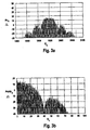
- Fig. 3a shows the optical spectrum with a NRZ signal modulated digital data sequence in front of the O / E (optical-electrical) converter 1.
- the O / E converter 1 in particular a photodiode, the E (electrical) field of the optical spectrum (Fig. 3a) with its conjugated complex component multiplied.
- the invention has for its object the disadvantages mentioned above to eliminate and an optical receiver of the generic type regarding the extraction of the clock signal from an optically transmitted Simplify NRZ data sequence. It also becomes a larger one spectral purity of the clock signal, i.e. less jitter, aimed for.
- the object is achieved with the characterizing features of claim 1 solved.
- the basic principle of the claimed solution consists of a clock branch for the regeneration of the clock signal not from the O / E converted signal but from the optical output signal derive.
- an optocoupler upstream of the O / E converter and an optical filter connected to this to split off a Part of the optical signal spectrum of the NRZ data sequence and one Evaluation circuit provided.
- the required optical Components, namely optocouplers and optical filters can be at least at very high bit rates, easier to manufacture than electrical ones Components for non-linear signal processing.
- the optical signal spectrum after the all-optical clock derivative O / E converted, due to the optical input Subspectrum also the electrical spectrum that contains the clock signal.
- the receiver illustrated in Fig. 1 is after an O / E converter 1 and an amplifier 3 in the electrical branch for Processing of the user data 4 uses a branching module 5 which is connected to a clock branch for extracting a clock signal 6.
- the clock branch consists of electrical series connected in series Components. These components essentially include one Amplifier 7, a non-linear signal processing 2, a bandpass filter 8 or PLL (phase locked loop) and a further amplifier 9.
- the useful data branch and the clock branch are more common Way via a digital flip-flop 10 and a clock distributor 11 connected with each other.
- Figures 3a and 3b can be seen that the optical spectrum - Fig.
- the solution illustrated in FIG. 2 differs from this prior art in that the optical input signal is already branched, only a part of the optical spectrum being used for the extraction of the clock signal 6.
- the branching is realized via an optocoupler 12 and the reduction to a part of the optical spectrum by means of an optical filter 13.
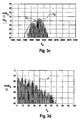
- an optical spectrum characterized in FIG. 3c results on the output side of the filter 13.
- the spectral composition depends on the filter characteristic Ao k in this example, which is chosen such that at least one clock line x 1 together with the optical carrier frequency x 2 is to be expected in the pass band of the optical filter 13.
- the filtered signal - FIG. 3 c - is fed to an O / E regenerator 14, which results in an electrical spectrum - FIG. 3 d - which corresponds to an electrical clock line x '- im corresponding to the difference between the optical spectral lines x 1 and x 2 Embodiment at 40 GHz - contains.
- the invention is not limited to the above Embodiment. Rather, a number of variants are conceivable which, even if the execution is fundamentally different, from the Make use of features of the invention. For example different types of optical filters, in particular Fabry-Perot filters, are used become.
Landscapes
- Physics & Mathematics (AREA)
- Electromagnetism (AREA)
- Engineering & Computer Science (AREA)
- Computer Networks & Wireless Communication (AREA)
- Signal Processing (AREA)
- Spectroscopy & Molecular Physics (AREA)
- Optical Communication System (AREA)
- Light Receiving Elements (AREA)
Abstract
Description
- Fig. 1
- eine schematische Darstellung eines optischen Empfängers gemäß dem Stand der Technik,
- Fig. 2
- eine ebensolche Darstellung eines erfindungsgemäßen Ausführungsbeispiels und
- die Fig. 3a bis 3d
- dem Empfängerschemata zugeordnete Signalverläufe.
Claims (2)
- Optischer Empfänger mit einem O/E-Wandler (1), insbesondere einer Fotodiode, und Mittel zur Extraktion eines Taktsignals (6) aus einer optischen übertragenen NRZ-Datenfolge,
dadurch gekennzeichnet, dass die Mittel einen dem O/E-Wandler (1) vorgeschalteten Optokoppler (12) und ein an den Optokoppler (12) angeschlossenes optisches Filter (13) zur Abspaltung eines Teiles des optischen Signalspektrums der NRZ-Datenfolge sowie eine Auswerteschaltung umfassen. - Optischer Empfänger nach Anspruch 1,
dadurch gekennzeichnet, dass die Auswerteschaltung einen O/E-Regenerator (14), insbesondere eine Fotodiode, eine Verstärkeranordnung und Mittel zur Filterung, insbesondere ein Bandpassfilter (8) oder ein PLL (phase locked loop), aufweist.
Applications Claiming Priority (2)
| Application Number | Priority Date | Filing Date | Title |
|---|---|---|---|
| DE10034451A DE10034451A1 (de) | 2000-07-15 | 2000-07-15 | Optischer Empfänger |
| DE10034451 | 2000-07-15 |
Publications (2)
| Publication Number | Publication Date |
|---|---|
| EP1172950A2 true EP1172950A2 (de) | 2002-01-16 |
| EP1172950A3 EP1172950A3 (de) | 2003-10-29 |
Family
ID=7649037
Family Applications (1)
| Application Number | Title | Priority Date | Filing Date |
|---|---|---|---|
| EP01440171A Withdrawn EP1172950A3 (de) | 2000-07-15 | 2001-06-14 | Optischer Empfänger |
Country Status (4)
| Country | Link |
|---|---|
| US (1) | US20020009159A1 (de) |
| EP (1) | EP1172950A3 (de) |
| JP (1) | JP2002094459A (de) |
| DE (1) | DE10034451A1 (de) |
Families Citing this family (2)
| Publication number | Priority date | Publication date | Assignee | Title |
|---|---|---|---|---|
| KR100674087B1 (ko) * | 2004-11-22 | 2007-01-24 | 한국전자통신연구원 | Nrz 신호의 비대칭 왜곡을 이용한 클럭 신호 생성 장치 및 그를 이용한 광송수신 시스템 |
| US9349121B2 (en) | 2014-06-27 | 2016-05-24 | Great Justice Systems Inc. | Professional service scheduling system and method |
Family Cites Families (6)
| Publication number | Priority date | Publication date | Assignee | Title |
|---|---|---|---|---|
| JPS562761A (en) * | 1979-06-20 | 1981-01-13 | Nec Corp | Clock reproducing circuit |
| JP2661438B2 (ja) * | 1991-09-24 | 1997-10-08 | 日本電気株式会社 | 光再生中継器 |
| JP3204463B2 (ja) * | 1992-06-06 | 2001-09-04 | キヤノン株式会社 | 波長多重光通信ネットワーク |
| EP0812074A3 (de) * | 1996-06-03 | 2002-02-06 | Nec Corporation | Optische Empfängerkarte, optisches Wellenlängenabstimmfilter für eine optische Empfängerkarte und Stellglied für ein optisches Wellenlängenabstimmfilter |
| FR2750552B1 (fr) * | 1996-06-26 | 1998-07-31 | Alcatel Submarcom | Recepteur pour systeme de transmission de signaux numeriques par voie optique |
| DE19754993A1 (de) * | 1997-12-11 | 1999-06-17 | Cit Alcatel | Optischer Empfänger für den Empfang von digital übertragenen Daten |
-
2000
- 2000-07-15 DE DE10034451A patent/DE10034451A1/de not_active Withdrawn
-
2001
- 2001-06-14 EP EP01440171A patent/EP1172950A3/de not_active Withdrawn
- 2001-07-04 JP JP2001203321A patent/JP2002094459A/ja not_active Withdrawn
- 2001-07-13 US US09/903,542 patent/US20020009159A1/en not_active Abandoned
Also Published As
| Publication number | Publication date |
|---|---|
| DE10034451A1 (de) | 2002-01-24 |
| US20020009159A1 (en) | 2002-01-24 |
| JP2002094459A (ja) | 2002-03-29 |
| EP1172950A3 (de) | 2003-10-29 |
Similar Documents
| Publication | Publication Date | Title |
|---|---|---|
| DE69800475T2 (de) | Optische Regenerierung für faseroptische Übertragungssysteme mit nicht-Soliton Signalen | |
| DE69512260T2 (de) | Rein optische verarbeitung in kommunikationssystemen | |
| DE60025975T2 (de) | Optischer Sender und Verfahren zur Steuerung des optischen Senders, die die Einstellung eines variablen Tastverhältnisses und die wechselnde Phaseninvertierung für optische Taktsignale verwendet | |
| DE69319792T2 (de) | Optische Regeneratorschaltung | |
| DE68904976T2 (de) | Verfahren und vorrichtung zur hinzufuegung und trennung eines digitalen kanales mit niedriger datenrate zum digitalen kanal mit hoher datenrate einer uebertragungsleitung. | |
| DE69603238T2 (de) | Rein optischer Frequenzverdoppler und dieser verwendender Solitonregenerator | |
| DE19904940A1 (de) | Optisches Übertragungssystem sowie Sender und Empfänger | |
| DE60126542T2 (de) | Optisches Übertragungssystem und optischer Empfänger | |
| DE60310344T2 (de) | Optische duobinäre Übertragung | |
| DE69324391T2 (de) | Vorrichtung zur optischen Wellenformung | |
| DE60107088T2 (de) | Ein CS-RZ optischer Taktgenerator und ein resynchronisierter optischer Multiplexer, der solch einen Generator enthält | |
| EP0657765B1 (de) | Optischer Phasenregelkreis | |
| EP1172950A2 (de) | Optischer Empfänger | |
| DE4328768A1 (de) | Verfahren und Schaltung zur Taktregenerierung | |
| DE60208145T2 (de) | Ultraschnelle Schaltung für Taktrückgewinnung optischer Signale | |
| DE102010004285A1 (de) | Netzelement | |
| DE60028522T2 (de) | Faseroptisches Übertragungssystem mit Rauschverminderung mittels nicht-linearem Offset des Signales | |
| EP0073400A1 (de) | Regenerator für digitale Signale mit quantisierter Rückkopplung | |
| DE60200236T2 (de) | Optische Vorrichtung für die Taktrückgewinnung eines optischen Signals | |
| DE69724750T2 (de) | Rein optisches Abtasten durch Modulation einer Impulsfolge | |
| DE69323694T2 (de) | Übertragungsnetz mit Vielfachzugriff | |
| DE102005037828B3 (de) | Verfahren und Vorrichtung zur rein-optischen Regeneration phasenmodulierter optischer Signale in Bezug auf Pulsform, Pulshöhe, Takt und Phase | |
| DE602004002160T2 (de) | Verfahren zur Bildung von einem kodierten RZ oder NRZ Signal | |
| EP1261138B1 (de) | Verfahren und Anordnung zur Duobinärcodierung einer Gruppe von Binärsignalen | |
| DE10333127B4 (de) | Verfahren und Anordnung zur Taktrückgewinnung eines hochbitratigen optischen Datensignals |
Legal Events
| Date | Code | Title | Description |
|---|---|---|---|
| PUAI | Public reference made under article 153(3) epc to a published international application that has entered the european phase |
Free format text: ORIGINAL CODE: 0009012 |
|
| AK | Designated contracting states |
Kind code of ref document: A2 Designated state(s): AT BE CH CY DE DK ES FI FR GB GR IE IT LI LU MC NL PT SE TR |
|
| AX | Request for extension of the european patent |
Free format text: AL;LT;LV;MK;RO;SI |
|
| PUAL | Search report despatched |
Free format text: ORIGINAL CODE: 0009013 |
|
| AK | Designated contracting states |
Kind code of ref document: A3 Designated state(s): AT BE CH CY DE DK ES FI FR GB GR IE IT LI LU MC NL PT SE TR |
|
| AX | Request for extension of the european patent |
Extension state: AL LT LV MK RO SI |
|
| AKX | Designation fees paid |
Designated state(s): AT BE CH CY DE DK ES FI FR GB GR IE IT LI LU MC NL PT SE TR |
|
| STAA | Information on the status of an ep patent application or granted ep patent |
Free format text: STATUS: THE APPLICATION IS DEEMED TO BE WITHDRAWN |
|
| 18D | Application deemed to be withdrawn |
Effective date: 20040430 |