EP1171227B1 - Verfahren und mikrovermischer zur herstellung einer dispersion - Google Patents
Verfahren und mikrovermischer zur herstellung einer dispersion Download PDFInfo
- Publication number
- EP1171227B1 EP1171227B1 EP00918836A EP00918836A EP1171227B1 EP 1171227 B1 EP1171227 B1 EP 1171227B1 EP 00918836 A EP00918836 A EP 00918836A EP 00918836 A EP00918836 A EP 00918836A EP 1171227 B1 EP1171227 B1 EP 1171227B1
- Authority
- EP
- European Patent Office
- Prior art keywords
- fluid
- lamellae
- micromixer
- dispersion
- stream
- Prior art date
- Legal status (The legal status is an assumption and is not a legal conclusion. Google has not performed a legal analysis and makes no representation as to the accuracy of the status listed.)
- Expired - Lifetime
Links
Images



Classifications
-
- B—PERFORMING OPERATIONS; TRANSPORTING
- B01—PHYSICAL OR CHEMICAL PROCESSES OR APPARATUS IN GENERAL
- B01J—CHEMICAL OR PHYSICAL PROCESSES, e.g. CATALYSIS OR COLLOID CHEMISTRY; THEIR RELEVANT APPARATUS
- B01J19/00—Chemical, physical or physico-chemical processes in general; Their relevant apparatus
- B01J19/0093—Microreactors, e.g. miniaturised or microfabricated reactors
-
- B—PERFORMING OPERATIONS; TRANSPORTING
- B01—PHYSICAL OR CHEMICAL PROCESSES OR APPARATUS IN GENERAL
- B01F—MIXING, e.g. DISSOLVING, EMULSIFYING OR DISPERSING
- B01F31/00—Mixers with shaking, oscillating, or vibrating mechanisms
- B01F31/80—Mixing by means of high-frequency vibrations above one kHz, e.g. ultrasonic vibrations
- B01F31/82—Mixing by means of high-frequency vibrations above one kHz, e.g. ultrasonic vibrations the material being forced through a narrow vibrating slit
-
- B—PERFORMING OPERATIONS; TRANSPORTING
- B01—PHYSICAL OR CHEMICAL PROCESSES OR APPARATUS IN GENERAL
- B01F—MIXING, e.g. DISSOLVING, EMULSIFYING OR DISPERSING
- B01F33/00—Other mixers; Mixing plants; Combinations of mixers
- B01F33/30—Micromixers
- B01F33/301—Micromixers using specific means for arranging the streams to be mixed, e.g. channel geometries or dispositions
- B01F33/3012—Interdigital streams, e.g. lamellae
-
- B—PERFORMING OPERATIONS; TRANSPORTING
- B01—PHYSICAL OR CHEMICAL PROCESSES OR APPARATUS IN GENERAL
- B01J—CHEMICAL OR PHYSICAL PROCESSES, e.g. CATALYSIS OR COLLOID CHEMISTRY; THEIR RELEVANT APPARATUS
- B01J2219/00—Chemical, physical or physico-chemical processes in general; Their relevant apparatus
- B01J2219/00781—Aspects relating to microreactors
- B01J2219/00889—Mixing
Definitions
- Dispersions of two or more fluids especially liquid-liquid Dispersions (emulsions) and gas-liquid dispersions play in many Areas such as drug preparation, cosmetics and Food, but also in chemical engineering, for example in multi-phase reactions, a major role.
- Micromixers have recently been used successfully for the production of dispersions.
- V. Hessel, et al. Gas / Liquid Dispersion Processes in Micromixers: The Hexagonal Flow, in Process Miniaturization: 2nd International Conference on Microreaction Technology, New La, 1998 and W. Ehrfeld et al., Application potentials of chemical and biological microreactors, Suitable miniaturized static mixers with capillary-like channels were described in yearbook 1997 - process engineering and chemical engineering, VDI-GVC 1997 . Using such miniaturized mixers, it was also possible to produce stable framed emulsions especially from silicone oil with water or an aqueous dye solution ( V.
- the stated object is achieved in that a fluid flow of the fluid A in spatially separated fluid lamellae is split. Then these Fluid lamellae are brought together with at least one fluid flow of the fluid B.
- the miscible fluids come in particular the combinations liquid-liquid and gaseous liquid in question. According to the method, it is also conceivable to have dispersions of three or to generate more fluids.
- the method according to the invention enables the process of fluid fragmentation to be able to influence them in a targeted manner. In this way, on the one hand narrower particle size distribution can be achieved. On the other hand, too the position of the maximum of this distribution can be influenced. By the The process therefore becomes possible with the micromixer and given flow velocities depending on the application from the same fluids A and B to produce different dispersions.
- both fluid flows are in fluid lamellae split and then each with a fluid lamella of fluid A. each brought together at least one fluid lamella of the fluid B.
- This enables, for example, a targeted merging of individuals Fluid lamellae. It can be advantageous to have one fluid lamella of the fluid A and at least one fluid lamella of the fluid B in a common channel to lead.
- a partial dispersion stream is formed in each case. The Partial dispersion streams are combined to form a dispersion stream.
- the fluid lamellae can also be offset from one another in a checkerboard fashion be directed to the space that each fluid lamella of some kind, for example four fluid lamellae of a different kind are surrounded and vice versa.
- the resulting one Dispersion is continuously drained from the room. Suitable for this Miniaturized mixers are used, for example, in EP 0 758 918 B1 Execution of chemical reactions described.
- the direction of flow of a fluid lamella can be essentially rectified with or opposite to the direction of flow of the fluid stream or Fluid lamella of the other fluid into which the fluid lamella is guided becomes.
- a fluid lamella at an angle of 0 ° to To supply 180 ° to the fluid flow or the fluid lamella.
- the fluid lamellae of fluid A and / or fluid B advantageously have a width of ⁇ 300 ⁇ m, particularly advantageously ⁇ 50 ⁇ m.
- the height of the corresponding fluid lamellae is preferably greater equal to their width, particularly preferably> 300 ⁇ m. Because of the comparison the width can be greater in height with essentially the same size distribution the particles forming the dispersion achieve a higher material throughput become.
- the fragmentation by mechanical vibrations is preferred in this way supports that at least areas of the fluid streams and / or the Fluid lamellae of the fluid A or / and the fluid B or / and the Dispersion stream are mechanically subjected to vibration. Areas of the fluid lamellae of the fluid A and / or the fluid B are particularly preferred applied. Areas of the fluid fins include areas in which the formation of the fluid fins takes place, and / or areas in which fluid lamellae of different types are brought together become. For this purpose, the part of a micromixer with vibrations is ideal acted upon in which the formation of the fluid lamellae takes place and / or in which the fluid lamellae different types are merged.
- the frequency of the mechanical vibrations is given the flow rate the fluid A and / or the fluid B selected with regard to the particle size to be achieved. This is made possible by the mechanical vibration of the process fragmentation is initiated. As a result, for a given vibration frequency a narrow size distribution of the particles is achieved, on the other hand with increasing or lowering the oscillation frequency the maximum of the size distribution shifted to smaller or larger particles.
- Mechanical vibrations in the frequency range from 1 kHz to 100 kHz are preferred, particularly preferably in the range from 10 kHz to 50 kHz.
- a dispersion with particles of fluid A or / and fluid is preferred B with a size of predominantly 0.1 to 100 ⁇ m, very particularly preferably of 0.1 up to 10 ⁇ m.
- Such emulsions advantageously have a standard deviation of Particle sizes ⁇ 5 ⁇ m. The standard deviation is particularly advantageously smaller equal to the mean size of the particles in ⁇ m.
- the micromixer according to the invention has a housing with at least two inlets for the fluids A and B and at least one outlet for the dispersion. Furthermore the micromixer has at least one mixing element with a structure for splitting at least the fluid flow of the fluid A in fluid lamellae.
- the micro mixer also includes at least one mixing area for bringing the fluid lamellae together of fluid A with the fluid flow of fluid B and at least one mechanical vibration generator to support the fragmentation of the fluid A and / or the fluid B in the Dispersion-forming particles which vibrate the part of the micromixer, In which the formation of the fluid lamellae takes place and / or in which the fluid lamellae differ kind of merged.
- the mixing element also advantageously has a structure for splitting the fluid flow of fluid B in fluid lamellae, with the mixing area for merging of fluid lamellae of the fluid A is formed with fluid lamellae of the fluid B.
- the mixing element has one of channels for the guidance of the fluid lamella of the fluid A and the fluid B formed interdigital structure on.
- the mixing element is advantageous over an element that is arranged transversely to the fluid lamellae Has gap, connected to the mixing area.
- This element is for example, a thin, slotted film.
- the element with the gap can also be an integral part of the element forming the mixing area.
- the mechanical one Vibration transmitter connected to the mixing element which for this purpose within the Micro mixer housing is movable. This allows the individual Fluid fins relative to the area where the fluid fins are brought together are periodically deflected.
- the mechanical one Vibrator connected to the element having the gap, the for this purpose is movable within the housing and relative to the mixing element. According to this embodiment, the area in which the fluid lamellae are brought together, relative to the area where the individual fluid lamellae generated, periodically deflected.
- both the mixing element and the gap having element with one or more vibrators connect.
- the mixing element and the gap are preferred having element movable out of phase with each other. Especially a phase shift of 180 ° is preferred.
- the Direction of movement of the mixing element parallel, orthogonal or in one other angle to that of the element having the gap.
- the micro-mixer is preferably designed so that the mixing element and / or the element having the gap parallel or perpendicular to the predetermined flow direction of the fluid lamella is movable.
- the mechanical vibration generator a piezoelectric actuator.
- mechanical vibration transmitter for example electromagnetic or pneumatic actuators or eccentric motors become.
- the vibrator (s) can be in the micromixer be integrated. With an arrangement outside the micromixer To provide elements that the mechanical vibration by the Forward the micro mixer housing to the elements to be moved.
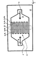
- FIG. 1 shows a known principle for splitting two fluid streams 2, 4 of the Fluids A, B in fluid lamellae 3a, 3b, ... and 5a, 5b1 ... shown.
- This is in a mixing element 12 an area of the supply 16 of the fluid A in channels 19a, 19b, ... divided to form fluid lamellae.
- An opposite The area of the feed 17 of the fluid B is also in channels 20a, 20b, ... for Formation of fluid lamellae divided, the channels 20a, 20b, ... between the channels 19a, 19b, ... are arranged and together a so-called Form interdigital structure 13.
- interdigital structure 13 of the Mixing element 12 is a further element, not shown here arranged that all areas of the mixing element 12 except for one over the Interdigital structure 13 lying, here indicated with dashed lines Gap 22 covers.
- the fins 3a, 3b, ..., 5a, 5b, ... of the fluids A and B flow adjacent to one another through the gap into an overlying one Mixing area not shown here.
- Silicone oil fluid fins when merging with the water fluid fins Silicone oil droplets fragment and an emulsion of silicone oil droplets in a continuous water phase is obtained. These were emulsions with volume ratios of water to diesel oil greater than 1: 1 finely dispersed, with smaller volume ratios, however, with a very broad distribution of the Sizes of silicone oil droplets.
- the geometry of the Micro mixer and fixed volume flows the size distribution of the Particles and the location of the maximum of the particles are not chosen directly become.
- An element 41 with a feed is in turn on the element 51 47 for the fluid flow B, a mixing area 48 and a discharge 43 arranged such that the mixing area 48 is above the Gap 52 is located.
- the feeder 47 and the mixing area 48 are as through the element 41 through recesses formed. Only by arranging the Element 41 on element 51 and by a not shown here, Through openings for the inlet and outlet cover plate, the to be arranged on the element 41, the feed area 47 and the mixing area formed 48 chamber-like channels. To achieve one of the same flow over all channels 49a, 49b, ... are microchannels provide sufficient pressure loss and a gap 52.
- the element 51 with the gap 52 is as small as possible Thickness, for example, formed as a slotted film. It is also conceivable instead of a gap 52 running across all channels 49a, 49b, ... Provide individual gaps in such a way that they are each exactly above a channel 49a, 49b, ... come to rest and cover the adjacent land areas.
- the Element 51 can also be an integral part of element 41.
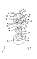
- FIG. 3 A known micromixer 1, which operates according to the principle explained in relation to FIG. 1, is shown in FIG. 3, three parts, the housing base 10a, the mixing element 12 and the housing cover 10b, being shown separately in perspective for the sake of clarity.
- the mixing element 12 has two feeds 16 and 17 and an interdigital structure 13 arranged between the two for forming fluid lamellae.
- the mixing element 12 can be inserted into a corresponding recess 11 in the housing base 10a.
- the housing cover 10b has two inlets 14, 15 which merge into bores for the feed 16, 17, which lie opposite the corresponding feed 16, 17 of the mixing element 12.
- an element 21 with a gap 22 is arranged such that the gap 22 comes to lie over the interdigital structure 13 of the mixing element 12.
- the mixing area 18 merges into an outlet 23, likewise indicated by dashed lines, which is connected to the outlet 24.
- an annular groove 27 for receiving an O-ring seal is incorporated in the base of the housing cover 10b.
- the housing base 10a has two dowel pins 28a on its upper side, which fit into corresponding bores 28b in the underside of the housing cover 10b.
- the housing cover 10b can be braced against the housing base 10a by means of four screws, not shown here, for which purpose four threaded bores 29 are provided in the base 10a and corresponding four through bores 30 are provided in the housing cover 10b.
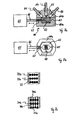
- the process of fragmentation is targeted by the Application of mechanical vibrations, such as ultrasound, is supported.
- Micro mixers suitable for this purpose and the associated processes of Fragmentation is shown in Figures 6a-c and 7a-c.
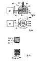
- FIG. 6a shows a micro-mixer 60 according to the invention with a mechanical vibration transmitter in the form of an ultrasonic transmitter 65 shown cut from the side.
- the cutting plane runs perpendicular to 4a and runs through the outlet 64 and parallel through the gap 63.
- the mixing element 62 is in a recess 61 of the housing base 60a movably arranged, the possible Direction of movement is indicated by the double arrow.
- the mixing element 62 is via a pin 66 with the one indicated only schematically here Ultrasound transmitter 65 connected, the pin through a through hole 67 is guided through the housing base 60a. Except for those with mobility of the mixing element 62 features this micromixer 60 has the same structure as the previously shown micromixer 1.
- the micro-mixer 60 is shown in FIG. 6b with the housing cover 60b removed Top view shown from above.
- the interdigital structure 68 in can be seen the mixing element 62 to form the fluid lamellae.
- the mixing element 62 is connected to the ultrasonic transmitter 65 via the pin 66 and thus in the Recess 61 arranged that the mixing element 62 perpendicular to the through Interdigital structure 68 predetermined flow direction of the fluid lamellae and so that it can be moved parallel to the alignment of the gap 63
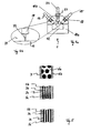
- FIG. 7a Another inventive micro mixer 80 with a movable Mixing element 62 is shown in section in FIG. 7a from the side.
- the Section plane runs perpendicular to the section plane and shown in FIG. 6a both through the two inlets 81 and 82 and perpendicular to the gap 63.
- FIGS. 7a-c for elements with the same Function the same reference numerals as used in Figure 6a-c.
- Oil-in-water emulsions were produced using the process according to the invention a water phase and a mixture of hard fat and triglycerides as Oil phase using the micromixer 60 shown in FIG. 6a manufactured.
- the 15 channels 19a, 19b, ..., 20a, 20b, ... in the Interdigital structure 68 of the mixing element 62 had a width of 40 ⁇ m and a depth of 300 ⁇ m.
- the one arranged above the interdigital structure 68 Gap 22 was 60 ⁇ m wide and 2 mm long used.
- the volume flow of the oil-water liquid flow became with 1.2 ml / h kept constant.
- the dispersion was at a constant temperature of 80 ° C and using 15 to 20 wt .-% of a glycerol ester as Emulsifier manufactured.
- the mixing element 62 With the ultrasonic transmitter 65, the mixing element 62 to a vibration with an amplitude of 10 to 20 ⁇ m and one Vibration frequency of 30 kHz excited.
- an average particle size became of about 1.17 ⁇ m with a standard deviation of 0.36 ⁇ m as this a representation of the particle size distribution measured with the light microscope in Fig. 8 shows.
- 68.3% of the droplets have a size in the range of 1.17 ⁇ m ⁇ 0.36 ⁇ m.
- FIG. 8 The direct comparison of FIG. 8 with FIG. 9 shows that with the Method according to the invention using the micro mixer 60 6a the size distribution of the particles forming the dispersion and the position of the maximum of the distribution can be influenced.
Landscapes
- Chemical & Material Sciences (AREA)
- Chemical Kinetics & Catalysis (AREA)
- Organic Chemistry (AREA)
- Colloid Chemistry (AREA)
- Emulsifying, Dispersing, Foam-Producing Or Wetting Agents (AREA)
- Pigments, Carbon Blacks, Or Wood Stains (AREA)
- Physical Or Chemical Processes And Apparatus (AREA)
Description
Es zeigen:
- Fig. 1
- das bekannte Prinzip des Aufspaltens zweier Fluidströme in Fluidlamellen,
- Fig. 2
- das bekannte Prinzip des Aufspaltens eines Fluidstroms in Fluidlamellen und Zusammenführens mit einem Fluidstrom,
- Fig. 3
- den Gehäuseboden, das Mischelement und den Gehäusedeckel eines bekannten Mikrovermischers getrennt voneinander in perspektivischer Darstellung,
- Fig. 4a
- den bekannten Mikrovermischer nach Fig. 3 geschnitten durch die Ebene der Einlässe und des Auslasses,
- Fig. 4b
- einen das Element mit Spalt darstellenden Ausschnitt aus Fig. 4a,
- Fig. 5
- den Übergang von parallelen Fluidlamellen über sich fragmentierende Fluidlamellen zu Fluidteilchen nach einem Mikrovermischer nach Fig. 3,
- Fig. 6a
- einen erfindungsgemäßen Mikrovermischer mit längs zum Spalt bewegbarem und an einem Ultraschallgeber gekoppelten Mischelement geschnitten von der Seite,
- Fig. 6b
- den Mikrovermischer nach Fig. 6a mit abgenommenem Gehäusedeckel in Draufsicht,
- Fig. 6c
- den Übergang von parallelen Fluidlamellen über sich fragmentierende Fluidlamellen zu Fluidteilchen nach dem Mikrovermischer nach Fig. 6a,
- Fig. 7a
- einen erfindungsgemäßen Mikrovermischer mit quer zum Spalt bewegbarem und an einem Ultraschallgeber gekoppelten Mischelement geschnitten von der Seite,
- Fig. 7b
- den Mikrovermischer nach Fig. 7a mit abgenommenem Gehäusedeckel in Draufsicht,
- Fig. 7c
- den Übergang von parallelen Fluidlamellen über sich fragmentierende Fluidlamellen zu Fluidteilchen nach dem Mikrovermischer nach Fig. 7a,
- Fig. 8
- Diagramm der mit dem erfindungsgemäßen Mikrovermischer nach Fig. 6a erhaltenen Teilchengrößenverteilung,
- Fig. 9
- Diagramm der mit einem bekannten Mikrovermischer nach Fig. 3 erhaltenen Teilchengrößenverteilung.
Das Mischelement 12 weist zwei Zuführungen 16 und 17 sowie eine zwischen beiden angeordnete Interdigitalstruktur 13 zur Bildung von Fluidlamellen auf. Das Mischelement 12 ist in eine entsprechende Ausnehmung 11 im Gehäuseboden 10a einsetzbar. Der Gehäusedeckel 10b weist zwei Einlässe 14, 15 auf, die in Bohrungen zur Zuführung 16, 17 übergehen, die der entsprechenden Zuführung 16, 17 des Mischelementes 12 gegenüberliegen. In den Boden des Gehäusedeckels 10b ist ein Element 21 mit einem Spalt 22 derart angeordnet, daß der Spalt 22 über der Interdigitalstruktur 13 des Mischelementes 12 zu liegen kommt. Im Gehäusedeckel 10b und oberhalb des Spalts 22 und mit diesem verbunden ist ein hier gestrichelt angedeuteter Vermischungsbereich 18 angeordnet, in dem die Fragmentation der Fluidlamellen zu den die Dispersion bildenden Teilchen stattfindet. Der Vermischungsbereich 18 geht in eine ebenfalls gestrichelt angedeutete Abführung 23 über, die mit dem Auslaß 24 verbunden ist. Zur Abdichtung zum Gehäuseboden 10a ist in den Boden des Gehäusedeckels 10b eine Ringnut 27 zur Aufnahme einer O-Ringdichtung eingearbeitet. Zur Positionierung von Gehäusedeckel 10b und -boden 10a zueinander weist der Gehäuseboden 10a auf seiner Oberseite zwei Paßstifte 28a auf, die in entsprechende Bohrungen 28b in der Unterseite des Gehäusedeckels 10b passen. Mittels vier hier nicht dargestellter Schrauben kann der Gehäusedeckel 10b gegen den Gehäuseboden 10a verspannt werden, wozu im Boden 10a vier mit Gewinde versehene Bohrungen 29 und im Gehäusedeckel 10b entsprechende vier Durchgangsbohrungen 30 vorgesehen sind.
- 1
- Mikrovermischer
- 2
- Fluidstrom A
- 3a, 3b, ...
- Fluidlamelle des Fluids A
- 4
- Fluidstrom B
- 5a, 5b, ...
- Fluidlamelle des Fluids B
- 6a, 6b, ...
- Teilchen Fluid A
- 7
- kontinuierliche Phase Fluid B
- 10a
- Gehäuseboden
- 10b
- Gehäusedeckel
- 11
- Ausnehmung
- 12
- Mischelement
- 13
- Interdigitalstruktur
- 14
- Einlaß für Fluidstrom A
- 15
- Einlaß für Fluidstrom B
- 16
- Zuführung für Fluidstrom A
- 17
- Zuführung für Fluidstrom B
- 18
- Vermischungsbereich
- 19a, 19b, ...
- Kanal für Fluidlamelle des Fluids A
- 20a, 20b, ...
- Kanal für Fluidlamelle des Fluids B
- 21
- Element mit Spalt
- 22
- Spalt
- 23
- Abführung
- 24
- Auslaß
- 27
- O-Ring-Nut
- 28a
- Paßstift
- 28b
- Bohrung
- 29
- Bohrung mit Gewinde
- 30
- Bohrung
- 41
- Element mit Vermischungsbereich
- 42
- Mischelement
- 43
- Abführung
- 46
- Zuführung für Fluidstrom A
- 47
- Zuführung für Fluidstrom B
- 48
- Vermischungsbereich
- 49a, 49b, ...
- Kanäle für Fluidlamellen des Fluids A
- 51
- Element mit Spalt
- 52
- Spalt
- 60
- Mikrovermischer
- 60a
- Gehäuseboden
- 60b
- Gehäusedeckel
- 61
- Ausnehmung
- 62
- Mischelement
- 63
- Spalt
- 64
- Auslaß
- 65
- Ultraschallgeber
- 66
- Stift
- 67
- Durchgangsöffnung
- 68
- Interdigitalstruktur
- 70a, 70b, ...
- Fluidlamelle des Fluids A
- 71a, 71b, ...
- Fluidlamelle des Fluids B
- 72a, 72b, ...
- Teilchen des Fluids A
- 73
- kontinuierliche Phase des Fluids B
- 80
- Mikrovermischer
- 81
- Einlaß für Fluidstrom des Fluids A
- 82
- Einlaß für Fluidstrom des Fluids B
Claims (17)
- Verfahren zur Herstellung einer Dispersion mindestens zweier Fluide A und B, bei dem das Größenverteilungsspektrum der die Dispersion bildenden Teilchen und die Lage des Maximums der Verteilung bei gegebener Strömungsgeschwindigkeit der Fluide beeinflußbar ist, das folgende Schritte umfaßt:a) Aufspaltung eines Fluidstroms (2) des Fluids A in räumlich voneinander getrennte Fluidlamellen (3a, 3b, ...),b) Zusammenführen der Fluidlamellen (3a, 3b, ...) des Fluids A mit mindestens einem Fluidstrom (4) des Fluids B, wobei die Fragmentation des Fluids A oder/und des Fluids B in die Dispersion bildende Teilchen (72a, 72b, ...) durch das Einleiten von in die zusammengeführten Fluidlamellen variierbaren, mechanischen Schwingungen initiiert und unterstützt wird, wobei das Einleiten derart erfolgt, daß den zusammengeführten Fluidlamellen ein wellenförmiger Verlauf verliehen wird.
- Verfahren nach Anspruch 1, dadurch gekennzeichnet, daß vor dem Zusammenführen der Fluidstrom (4) des Fluids B in Fluidlamellen (5a, 5b, ...) aufgespalten wird, und daß anschließend jeweils eine Fluidlamelle (3a, 3b, ...) des Fluids A mit jeweils mindestens einer Fluidlamelle (5a, 5b, ...) des Fluids B zusammengeführt wird.
- Verfahren nach Anspruch 1, dadurch gekennzeichnet, daß mehrere Fluidlamellen des Fluids A und mehrere Fluidlamellen des Fluids B derart gemeinsam in einen Raum geleitet werden, daß jeweils eine Fluidlamelle des Fluids A benachbart mit mindestens einer Fluidlamelle des Fluids b in diesen Raum austritt.
- Verfahren nach einem der forherigen Ansprüche, dadurch gekennzeichnet, daß die Breite der Fluidlamellen des Fluids A oder /und des Fluids B < 300 µm, vorzugsweise < 50 µm, ist.
- Verfahren nach einem der vorherigen Ansprüche, dadurch gekennzeichnet, daß die Höhe der Fluidlamellen des Fluids A oder/und des Fluids B größer gleich der Breite der entsprechenden Fluidlamellen, vorzugsweise > 300 µm, ist.
- Verfahren nach einem der vorherigen Ansprüche, dadurch gekennzeichnet, daß die Fragmentation durch mechanische Schwingungen derart unterstützt wird, daß zumindest Bereiche der Fluidströme oder/und der Fluidlamellen des Fluids A oder/und des Fluids B oder/und des Dispersionstromes mechanisch mit Schwingung beaufschlagt werden.
- Verfahren nach einem der vorherigen Ansprüche, dadurch gekennzeichnet, daß eine Dispersion mit Teilchen des Fluids A oder/und des Fluids B mit einer Größe von überwiegend 1 bis 100 µm hergestellt wird.
- Verfahren nach einem der vorherigen Ansprüche, dadurch gekennzeichnet, daß die Frequenz der mechanischen Schwingungen bei gegebener Strömungsgeschwindigkeit des Fluids A und/oder des Fluids B im Hinblick auf die zu erzielende Teilchengröße gewählt wird.
- Verfehlen nach einem der vorherigen Ansprüche, gekennzeichnet durch mechanische Schwingungen im Frequenzbereich von 1 kHz bis 100 kHz, vorzugsweise von 10 kHz bis 50 kHz.
- Mikrovermischer (60, 80) zur Herstellung von Dispersionen mindestens zweier Fluide A und Bmit einem Gehäuse (60a, 60b) mit mindestens zwei Einlässen (81, 82) für die Fluide A und B sowie mindestens einem Auslaß (64) für die Dispersion,mit mindestens einem Mischelement (62), das eine Struktur zum Aufspalten mindestens des Fluidstroms (2) des Fluids A in Fluidlamellen (3a, 3b, ...) aufweist,mit mindestens einem Vermischungsbereich zum Zusammenführen der Fluidlamellen (3a, 3b, ...) des Fluids A mit dem Fluidstrom des Fluids B undmit mindestens einem in seiner Frequenz, Amplitude, Schwingungsebene und/oder Energie einstellbaren, mechanischen Schwingungsgeber (65) zur Beaufschlagung des Teils des Mikrovermischers mit Schwingungen, in dem die Bildung der Fluidlamellen erfolgt oder/und in dem die Fluidlamellen unterschiedlicher Art zusammengeführt werden.
- Mikrovermischer (60, 80) nach Anspruch 10, dadurch gekennzeichnet, daß das Mischelement (62) ebenfalls eine Struktur zum Aufspalten des Fluidstroms (4) des Fluids B in Fluidlamellen (5a, 5b, ...) aufweist, wobei der Vermischungsbereich zum Zusammenführen von Fluidlamellen (3a, 3b, ...) des Fluids A mit Fluidlamellen (5a, 5b, ...) des Fluids B ausgebildet ist.
- Mikrovermischer (60, 80) nach Anspruch 11, dadurch gekennzeichnet, daß das Mischelement (62) eine aus Kanälen (19a, 19b, ..., 20a, 20b, ...) für die Führung der Fluidlamellen (3a, 3b, ..., 5a, 5b, ...) des Fluids A und des Fluids B gebildete interdigitale Struktur (68) aufweist.
- Mikrovermischer (60, 80) nach einem der Ansprüche 10 bis 12, dadurch gekennzeichnet, daß das Mischelement (62) über ein Element, das einen quer zu den Fluidlamellen angeordneten Spalt (63) aufweist, mit dem Vermischungsbereich verbunden ist.
- Mikrovermischer (60, 80) nach einem der Ansprüche 10 bis 13, dadurch gekennzeichnet, daß der mechanische Schwingungsgeber (65) mit dem Mischelement (62) verbunden ist, welches innerhalb des Gehäuses (60a, 60b) des Mikrovermischers (60, 80) bewegbar ist.
- Mikrovermischer nach einem der Ansprüche 10 bis 13, dadurch gekennzeichnet, daß der mechanische Schwingungsgeber mit dem den Spalt aufweisenden Element verbunden ist, welches relativ zum Mischelement innerhalb des Gehäuses des Mikrovermischers bewegbar ist.
- Mikrovermischer (60, 80) nach Anspruch 14 oder 15, dadurch gekennzeichnet, daß das Mischelement (62) oder/und das den Spalt aufweisende Element parallel oder senkrecht zu der vorgegebenen Strömungsrichtung der Fluidlamellen (3a, 3b, ..., 5a, 5b, ...) bewegbar ist.
- Mikrovermischer nach einem der Ansprüche 10 bis 16, dadurch gekennzeichnet, daß der mechanische Schwingungsgeber einen piezoelektrischen Aktuator aufweist,
Applications Claiming Priority (3)
| Application Number | Priority Date | Filing Date | Title |
|---|---|---|---|
| DE19917148A DE19917148C2 (de) | 1999-04-16 | 1999-04-16 | Verfahren und Mikrovermischer zur Herstellung einer Dispersion |
| DE19917148 | 1999-04-16 | ||
| PCT/EP2000/002655 WO2000062913A1 (de) | 1999-04-16 | 2000-03-25 | Verfahren und mikrovermischer zur herstellung einer dispersion |
Publications (2)
| Publication Number | Publication Date |
|---|---|
| EP1171227A1 EP1171227A1 (de) | 2002-01-16 |
| EP1171227B1 true EP1171227B1 (de) | 2003-06-18 |
Family
ID=7904741
Family Applications (1)
| Application Number | Title | Priority Date | Filing Date |
|---|---|---|---|
| EP00918836A Expired - Lifetime EP1171227B1 (de) | 1999-04-16 | 2000-03-25 | Verfahren und mikrovermischer zur herstellung einer dispersion |
Country Status (4)
| Country | Link |
|---|---|
| EP (1) | EP1171227B1 (de) |
| AT (1) | ATE243068T1 (de) |
| DE (2) | DE19917148C2 (de) |
| WO (1) | WO2000062913A1 (de) |
Cited By (3)
| Publication number | Priority date | Publication date | Assignee | Title |
|---|---|---|---|---|
| US7307104B2 (en) | 2003-05-16 | 2007-12-11 | Velocys, Inc. | Process for forming an emulsion using microchannel process technology |
| US7485671B2 (en) | 2003-05-16 | 2009-02-03 | Velocys, Inc. | Process for forming an emulsion using microchannel process technology |
| US7622509B2 (en) | 2004-10-01 | 2009-11-24 | Velocys, Inc. | Multiphase mixing process using microchannel process technology |
Families Citing this family (43)
| Publication number | Priority date | Publication date | Assignee | Title |
|---|---|---|---|---|
| US7708749B2 (en) | 2000-12-20 | 2010-05-04 | Fox Hollow Technologies, Inc. | Debulking catheters and methods |
| US7713279B2 (en) | 2000-12-20 | 2010-05-11 | Fox Hollow Technologies, Inc. | Method and devices for cutting tissue |
| US8328829B2 (en) | 1999-08-19 | 2012-12-11 | Covidien Lp | High capacity debulking catheter with razor edge cutting window |
| US6299622B1 (en) | 1999-08-19 | 2001-10-09 | Fox Hollow Technologies, Inc. | Atherectomy catheter with aligned imager |
| DE10063027A1 (de) * | 2000-12-18 | 2002-06-20 | Merck Patent Gmbh | Verwendung eines Mikroreaktionskanals mit Piezoelement |
| DE60144107D1 (de) | 2000-12-20 | 2011-04-07 | Fox Hollow Technologies Inc | Verkleinerungskatheter |
| DE10109589A1 (de) * | 2001-02-28 | 2002-09-12 | Merck Patent Gmbh | Mikroreaktor |
| US6605422B2 (en) | 2001-03-16 | 2003-08-12 | Fuji Photo Film Co., Ltd. | Process for producing a silver halide photographic emulsion |
| JP2002282678A (ja) * | 2001-03-28 | 2002-10-02 | Fuji Photo Film Co Ltd | マイクロカプセルの製造方法および感熱記録材料 |
| JP2002282679A (ja) * | 2001-03-28 | 2002-10-02 | Fuji Photo Film Co Ltd | マイクロカプセルの製造方法および感熱記録材料 |
| DE10206083B4 (de) * | 2002-02-13 | 2009-11-26 | INSTITUT FüR MIKROTECHNIK MAINZ GMBH | Verfahren zum Erzeugen monodisperser Nanotropfen sowie mikrofluidischer Reaktor zum Durchführen des Verfahrens |
| EP1356857B1 (de) * | 2002-04-16 | 2006-06-21 | Fuchs Lubritech Gmbh | Verfahren zur Herstellung und Aufbringung von emulgatorfreien Öl-in-Wasser-Dispersionen als Trennmittel oder Kühlschmierstoff |
| US6910797B2 (en) | 2002-08-14 | 2005-06-28 | Hewlett-Packard Development, L.P. | Mixing device having sequentially activatable circulators |
| US8246640B2 (en) | 2003-04-22 | 2012-08-21 | Tyco Healthcare Group Lp | Methods and devices for cutting tissue at a vascular location |
| JP4407177B2 (ja) | 2003-05-30 | 2010-02-03 | 富士フイルム株式会社 | マイクロリアクターを用いた反応方法 |
| JP4432104B2 (ja) | 2003-05-30 | 2010-03-17 | 富士フイルム株式会社 | マイクロリアクター |
| JP4431857B2 (ja) | 2003-05-30 | 2010-03-17 | 富士フイルム株式会社 | マイクロデバイス |
| DE20315371U1 (de) * | 2003-10-02 | 2005-02-17 | Thinxxs Gmbh | Verbinder zur Herstellung von Fluidverbindungen |
| JP2005187450A (ja) * | 2003-12-01 | 2005-07-14 | Nippon Steel Chem Co Ltd | ビスフェノール類の製造方法 |
| JP4485178B2 (ja) * | 2003-12-01 | 2010-06-16 | 新日鐵化学株式会社 | ビスフェノール類の製造方法 |
| JP4547606B2 (ja) | 2004-03-17 | 2010-09-22 | 富士フイルム株式会社 | マイクロリアクターの複合反応方法及びマイクロリアクター |
| US7795359B2 (en) | 2005-03-04 | 2010-09-14 | Novartis Ag | Continuous process for production of polymeric materials |
| DE102005025248B4 (de) * | 2005-06-02 | 2009-07-30 | Forschungszentrum Karlsruhe Gmbh | Fluidführungssystem |
| US20070276419A1 (en) | 2006-05-26 | 2007-11-29 | Fox Hollow Technologies, Inc. | Methods and devices for rotating an active element and an energy emitter on a catheter |
| US8784440B2 (en) | 2008-02-25 | 2014-07-22 | Covidien Lp | Methods and devices for cutting tissue |
| CN102223847B (zh) | 2008-10-13 | 2013-10-30 | 泰科保健集团有限合伙公司 | 用于操纵导管轴的装置和方法 |
| KR101323553B1 (ko) | 2009-04-29 | 2013-10-29 | 코비디엔 엘피 | 조직을 절제하고 연마하기 위한 방법 및 장치 |
| NL2002862C2 (en) * | 2009-05-08 | 2010-11-09 | Friesland Brands Bv | Microfluidic apparatus and method for generating a dispersion. |
| KR101581091B1 (ko) | 2009-05-14 | 2015-12-30 | 코비디엔 엘피 | 세척이 용이한 죽상반 절제 카테터 및 사용 방법 |
| EP2913013B1 (de) | 2009-12-02 | 2016-11-09 | Covidien LP | Verfahren und Vorrichtung zum Schneiden von Gewebe |
| IN2012DN04977A (de) | 2009-12-11 | 2015-09-25 | Tyco Healthcare | |
| WO2011159697A1 (en) | 2010-06-14 | 2011-12-22 | Tyco Healthcare Group Lp | Material removal device |
| WO2012058438A1 (en) | 2010-10-28 | 2012-05-03 | Tyco Healthcare Group Lp | Material removal device and method of use |
| RU2553930C2 (ru) | 2010-11-11 | 2015-06-20 | Ковидиен Лп | Гибкие фрагментирующие катетеры с визуализацией и способы их использования и изготовления |
| JP5806407B2 (ja) | 2011-09-01 | 2015-11-10 | コヴィディエン リミテッド パートナーシップ | 螺旋駆動軸を有するカテーテルおよび製造方法 |
| US9579157B2 (en) | 2012-09-13 | 2017-02-28 | Covidien Lp | Cleaning device for medical instrument and method of use |
| JP6008685B2 (ja) | 2012-10-12 | 2016-10-19 | イー インク コーポレイション | 表示用粒子分散液、表示媒体、及び表示装置 |
| US9943329B2 (en) | 2012-11-08 | 2018-04-17 | Covidien Lp | Tissue-removing catheter with rotatable cutter |
| WO2015200702A1 (en) | 2014-06-27 | 2015-12-30 | Covidien Lp | Cleaning device for catheter and catheter including the same |
| US10314667B2 (en) | 2015-03-25 | 2019-06-11 | Covidien Lp | Cleaning device for cleaning medical instrument |
| US10292721B2 (en) | 2015-07-20 | 2019-05-21 | Covidien Lp | Tissue-removing catheter including movable distal tip |
| US10314664B2 (en) | 2015-10-07 | 2019-06-11 | Covidien Lp | Tissue-removing catheter and tissue-removing element with depth stop |
| CN112295616B (zh) * | 2020-09-11 | 2022-03-18 | 东南大学 | 一种微液滴混合强化微流控装置 |
Family Cites Families (10)
| Publication number | Priority date | Publication date | Assignee | Title |
|---|---|---|---|---|
| US4259021A (en) * | 1978-04-19 | 1981-03-31 | Paul R. Goudy, Jr. | Fluid mixing apparatus and method |
| US4908154A (en) * | 1981-04-17 | 1990-03-13 | Biotechnology Development Corporation | Method of forming a microemulsion |
| JP2847107B2 (ja) * | 1989-02-16 | 1999-01-13 | 富士シリシア化学株式会社 | エマルジョンの調製方法 |
| DE4226850A1 (de) * | 1992-03-23 | 1993-09-30 | Roiner Franz | Verfahren zur Behandlung und/oder Herstellung einer Emulsion, insbesondere einer Fettemulsion |
| DE4304260A1 (de) * | 1993-02-12 | 1994-08-18 | Marco Systemanalyse Entw | Vorrichtung zum Herstellen einer Emulsion |
| ES2120204T3 (es) * | 1994-05-09 | 1998-10-16 | Bayer Ag | Procedimiento y dispositivo para la realizacion de reacciones quimicas por medio de una mezcla de microestructura. |
| DE19612349A1 (de) * | 1996-03-28 | 1997-12-11 | Alois Dipl Ing Fleig | Apparat und Verfahren zur Behandlung und Herstellung von mehrphasigen Flüssigkeiten, Emulsionen und Suspensionen |
| US6065864A (en) * | 1997-01-24 | 2000-05-23 | The Regents Of The University Of California | Apparatus and method for planar laminar mixing |
| DE19705364C2 (de) * | 1997-02-12 | 1998-12-17 | Ott Kg Lewa | Verfahren und Vorrichtung zur Sprühverteilung mittels Ultraschall |
| DE19728520A1 (de) * | 1997-07-04 | 1999-01-07 | Imb Inst Fuer Molekulare Biote | Schaltbarer dynamischer Mikromischer mit minimalem Totvolumen |
-
1999
- 1999-04-16 DE DE19917148A patent/DE19917148C2/de not_active Expired - Fee Related
-
2000
- 2000-03-25 WO PCT/EP2000/002655 patent/WO2000062913A1/de not_active Ceased
- 2000-03-25 DE DE50002593T patent/DE50002593D1/de not_active Expired - Lifetime
- 2000-03-25 EP EP00918836A patent/EP1171227B1/de not_active Expired - Lifetime
- 2000-03-25 AT AT00918836T patent/ATE243068T1/de not_active IP Right Cessation
Cited By (4)
| Publication number | Priority date | Publication date | Assignee | Title |
|---|---|---|---|---|
| US7307104B2 (en) | 2003-05-16 | 2007-12-11 | Velocys, Inc. | Process for forming an emulsion using microchannel process technology |
| US7485671B2 (en) | 2003-05-16 | 2009-02-03 | Velocys, Inc. | Process for forming an emulsion using microchannel process technology |
| US7622509B2 (en) | 2004-10-01 | 2009-11-24 | Velocys, Inc. | Multiphase mixing process using microchannel process technology |
| US7816411B2 (en) | 2004-10-01 | 2010-10-19 | Velocys, Inc. | Multiphase mixing process using microchannel process technology |
Also Published As
| Publication number | Publication date |
|---|---|
| DE50002593D1 (de) | 2003-07-24 |
| EP1171227A1 (de) | 2002-01-16 |
| ATE243068T1 (de) | 2003-07-15 |
| WO2000062913A1 (de) | 2000-10-26 |
| DE19917148C2 (de) | 2002-01-10 |
| DE19917148A1 (de) | 2000-10-26 |
Similar Documents
| Publication | Publication Date | Title |
|---|---|---|
| DE19917148C2 (de) | Verfahren und Mikrovermischer zur Herstellung einer Dispersion | |
| EP1311341B1 (de) | Verfahren und statischer mikrovermischer zum mischen mindestens zweier fluide | |
| EP0956151B1 (de) | Verfahren und vorrichtung zur herstellung eines dispersen gemisches | |
| EP1390131B1 (de) | Verfahren und statischer mikrovermischer zum mischen mindestens zweier fluide | |
| EP0758918B1 (de) | Verfahren und vorrichtung zur durchführung chemischer reaktionen mittels mikrostruktur-mischung | |
| DE102005037401B4 (de) | Bildung einer Emulsion in einem fluidischen Mikrosystem | |
| DE60211857T2 (de) | Verfahren zur herstellung einer emulsion und vorrichtung dafür | |
| DE3851106T2 (de) | Vorrichtung zum Mischen fliessfähiger Medien. | |
| DE10123092B4 (de) | Verfahren und statischer Mischer zum Mischen mindestens zweier Fluide | |
| EP1866066B1 (de) | Mischersystem, Reaktor und Reaktorsystem | |
| DE19908171A1 (de) | Kontinuierliches Herstellungsverfahren für Mikrokugeln und Vorrichtung hierfür | |
| DE19748481C2 (de) | Statischer Mikrovermischer | |
| DE19541265A1 (de) | Verfahren zur Herstellung von Dispersionen und zur Durchführung chemischer Reaktionen mit disperser Phase | |
| DE19917156B4 (de) | Verfahren zur Herstellung einer Wasser-in-Dieselöl-Emulsion als Kraftstoff sowie dessen Verwendungen | |
| DE19927556A1 (de) | Statischer Mikromischer | |
| DE10206083B4 (de) | Verfahren zum Erzeugen monodisperser Nanotropfen sowie mikrofluidischer Reaktor zum Durchführen des Verfahrens | |
| WO2001089693A1 (de) | Emulgier- und trennvorrichtung für flüssige phasen | |
| EP2049235B1 (de) | Emulgiereinrichtung und verfahren zur bildung einer emulsion | |
| DE102021110094A1 (de) | Vorrichtung und Verfahren zum Mischen von Fluiden und zum Erzeugen eines Fluidgemisches | |
| DE10159985B4 (de) | Mikroemulgator | |
| DE10213003B4 (de) | Mikromischer und Verfahren zum Mischen von mindestens zwei Flüssigkeiten und Verwendung von Mikromischern | |
| EP2662131B1 (de) | Emulgiervorrichtung | |
| DE20219871U1 (de) | Rautenmischer | |
| DE4433439A1 (de) | Verfahren zur Durchführung chemischer Reaktionen mittels Mikrostruktur-Mischung | |
| WO2003089129A1 (de) | Integriertes misch- und schaltsystem für die mikroreaktionstechnik |
Legal Events
| Date | Code | Title | Description |
|---|---|---|---|
| PUAI | Public reference made under article 153(3) epc to a published international application that has entered the european phase |
Free format text: ORIGINAL CODE: 0009012 |
|
| 17P | Request for examination filed |
Effective date: 20010919 |
|
| AK | Designated contracting states |
Kind code of ref document: A1 Designated state(s): AT BE CH CY DE DK ES FI FR GB GR IE IT LI LU MC NL PT SE |
|
| 17Q | First examination report despatched |
Effective date: 20020620 |
|
| GRAH | Despatch of communication of intention to grant a patent |
Free format text: ORIGINAL CODE: EPIDOS IGRA |
|
| GRAH | Despatch of communication of intention to grant a patent |
Free format text: ORIGINAL CODE: EPIDOS IGRA |
|
| GRAA | (expected) grant |
Free format text: ORIGINAL CODE: 0009210 |
|
| AK | Designated contracting states |
Designated state(s): AT BE CH CY DE DK ES FI FR GB GR IE IT LI LU MC NL PT SE |
|
| PG25 | Lapsed in a contracting state [announced via postgrant information from national office to epo] |
Ref country code: IT Free format text: LAPSE BECAUSE OF FAILURE TO SUBMIT A TRANSLATION OF THE DESCRIPTION OR TO PAY THE FEE WITHIN THE PRESCRIBED TIME-LIMIT;WARNING: LAPSES OF ITALIAN PATENTS WITH EFFECTIVE DATE BEFORE 2007 MAY HAVE OCCURRED AT ANY TIME BEFORE 2007. THE CORRECT EFFECTIVE DATE MAY BE DIFFERENT FROM THE ONE RECORDED. Effective date: 20030618 Ref country code: IE Free format text: LAPSE BECAUSE OF FAILURE TO SUBMIT A TRANSLATION OF THE DESCRIPTION OR TO PAY THE FEE WITHIN THE PRESCRIBED TIME-LIMIT Effective date: 20030618 Ref country code: NL Free format text: LAPSE BECAUSE OF FAILURE TO SUBMIT A TRANSLATION OF THE DESCRIPTION OR TO PAY THE FEE WITHIN THE PRESCRIBED TIME-LIMIT Effective date: 20030618 Ref country code: CY Free format text: LAPSE BECAUSE OF FAILURE TO SUBMIT A TRANSLATION OF THE DESCRIPTION OR TO PAY THE FEE WITHIN THE PRESCRIBED TIME-LIMIT Effective date: 20030618 Ref country code: FI Free format text: LAPSE BECAUSE OF FAILURE TO SUBMIT A TRANSLATION OF THE DESCRIPTION OR TO PAY THE FEE WITHIN THE PRESCRIBED TIME-LIMIT Effective date: 20030618 Ref country code: FR Free format text: LAPSE BECAUSE OF FAILURE TO SUBMIT A TRANSLATION OF THE DESCRIPTION OR TO PAY THE FEE WITHIN THE PRESCRIBED TIME-LIMIT Effective date: 20030618 Ref country code: GB Free format text: LAPSE BECAUSE OF FAILURE TO SUBMIT A TRANSLATION OF THE DESCRIPTION OR TO PAY THE FEE WITHIN THE PRESCRIBED TIME-LIMIT Effective date: 20030618 |
|
| REG | Reference to a national code |
Ref country code: GB Ref legal event code: FG4D Free format text: NOT ENGLISH |
|
| REG | Reference to a national code |
Ref country code: CH Ref legal event code: EP |
|
| REG | Reference to a national code |
Ref country code: IE Ref legal event code: FG4D Free format text: GERMAN |
|
| REF | Corresponds to: |
Ref document number: 50002593 Country of ref document: DE Date of ref document: 20030724 Kind code of ref document: P |
|
| PG25 | Lapsed in a contracting state [announced via postgrant information from national office to epo] |
Ref country code: SE Free format text: LAPSE BECAUSE OF FAILURE TO SUBMIT A TRANSLATION OF THE DESCRIPTION OR TO PAY THE FEE WITHIN THE PRESCRIBED TIME-LIMIT Effective date: 20030918 Ref country code: PT Free format text: LAPSE BECAUSE OF FAILURE TO SUBMIT A TRANSLATION OF THE DESCRIPTION OR TO PAY THE FEE WITHIN THE PRESCRIBED TIME-LIMIT Effective date: 20030918 Ref country code: DK Free format text: LAPSE BECAUSE OF FAILURE TO SUBMIT A TRANSLATION OF THE DESCRIPTION OR TO PAY THE FEE WITHIN THE PRESCRIBED TIME-LIMIT Effective date: 20030918 Ref country code: GR Free format text: LAPSE BECAUSE OF FAILURE TO SUBMIT A TRANSLATION OF THE DESCRIPTION OR TO PAY THE FEE WITHIN THE PRESCRIBED TIME-LIMIT Effective date: 20030918 |
|
| PG25 | Lapsed in a contracting state [announced via postgrant information from national office to epo] |
Ref country code: ES Free format text: LAPSE BECAUSE OF FAILURE TO SUBMIT A TRANSLATION OF THE DESCRIPTION OR TO PAY THE FEE WITHIN THE PRESCRIBED TIME-LIMIT Effective date: 20030929 |
|
| NLV1 | Nl: lapsed or annulled due to failure to fulfill the requirements of art. 29p and 29m of the patents act | ||
| GBV | Gb: ep patent (uk) treated as always having been void in accordance with gb section 77(7)/1977 [no translation filed] |
Effective date: 20030618 |
|
| REG | Reference to a national code |
Ref country code: IE Ref legal event code: FD4D |
|
| PG25 | Lapsed in a contracting state [announced via postgrant information from national office to epo] |
Ref country code: LU Free format text: LAPSE BECAUSE OF NON-PAYMENT OF DUE FEES Effective date: 20040325 Ref country code: AT Free format text: LAPSE BECAUSE OF NON-PAYMENT OF DUE FEES Effective date: 20040325 |
|
| PG25 | Lapsed in a contracting state [announced via postgrant information from national office to epo] |
Ref country code: CH Free format text: LAPSE BECAUSE OF NON-PAYMENT OF DUE FEES Effective date: 20040331 Ref country code: LI Free format text: LAPSE BECAUSE OF NON-PAYMENT OF DUE FEES Effective date: 20040331 Ref country code: BE Free format text: LAPSE BECAUSE OF NON-PAYMENT OF DUE FEES Effective date: 20040331 Ref country code: MC Free format text: LAPSE BECAUSE OF NON-PAYMENT OF DUE FEES Effective date: 20040331 |
|
| PLBE | No opposition filed within time limit |
Free format text: ORIGINAL CODE: 0009261 |
|
| STAA | Information on the status of an ep patent application or granted ep patent |
Free format text: STATUS: NO OPPOSITION FILED WITHIN TIME LIMIT |
|
| 26N | No opposition filed |
Effective date: 20040319 |
|
| EN | Fr: translation not filed | ||
| BERE | Be: lapsed |
Owner name: INSTITUT FUR MIKROTECHNIK *MAINZ G.M.B.H. Effective date: 20040331 |
|
| REG | Reference to a national code |
Ref country code: CH Ref legal event code: PL |
|
| REG | Reference to a national code |
Ref country code: DE Ref legal event code: R084 Ref document number: 50002593 Country of ref document: DE |
|
| REG | Reference to a national code |
Ref country code: DE Ref legal event code: R082 Ref document number: 50002593 Country of ref document: DE |
|
| REG | Reference to a national code |
Ref country code: DE Ref legal event code: R084 Ref document number: 50002593 Country of ref document: DE Effective date: 20150311 Ref country code: DE Ref legal event code: R081 Ref document number: 50002593 Country of ref document: DE Owner name: FRAUNHOFER-GESELLSCHAFT ZUR FOERDERUNG DER ANG, DE Free format text: FORMER OWNER: INSTITUT FUER MIKROTECHNIK MAINZ GMBH, 55129 MAINZ, DE Effective date: 20150317 |
|
| PGFP | Annual fee paid to national office [announced via postgrant information from national office to epo] |
Ref country code: DE Payment date: 20190325 Year of fee payment: 20 |
|
| PGFP | Annual fee paid to national office [announced via postgrant information from national office to epo] |
Ref country code: DE Payment date: 20190325 Year of fee payment: 20 |