EP1170552A2 - Dispositif de distribution de liquides - Google Patents
Dispositif de distribution de liquides Download PDFInfo
- Publication number
- EP1170552A2 EP1170552A2 EP01115543A EP01115543A EP1170552A2 EP 1170552 A2 EP1170552 A2 EP 1170552A2 EP 01115543 A EP01115543 A EP 01115543A EP 01115543 A EP01115543 A EP 01115543A EP 1170552 A2 EP1170552 A2 EP 1170552A2
- Authority
- EP
- European Patent Office
- Prior art keywords
- valve
- spindle
- shut
- handwheel
- drain
- Prior art date
- Legal status (The legal status is an assumption and is not a legal conclusion. Google has not performed a legal analysis and makes no representation as to the accuracy of the status listed.)
- Granted
Links
- 239000007788 liquid Substances 0.000 title claims description 4
- XLYOFNOQVPJJNP-UHFFFAOYSA-N water Substances O XLYOFNOQVPJJNP-UHFFFAOYSA-N 0.000 claims abstract description 13
- 238000007789 sealing Methods 0.000 claims description 9
- 238000010438 heat treatment Methods 0.000 claims description 5
- 239000003651 drinking water Substances 0.000 claims description 3
- 230000035622 drinking Effects 0.000 claims description 2
- 239000008235 industrial water Substances 0.000 claims description 2
- 230000001419 dependent effect Effects 0.000 description 1
- 238000011161 development Methods 0.000 description 1
- 230000018109 developmental process Effects 0.000 description 1
- 238000006073 displacement reaction Methods 0.000 description 1
- 235000020188 drinking water Nutrition 0.000 description 1
- 238000005516 engineering process Methods 0.000 description 1
- 230000002349 favourable effect Effects 0.000 description 1
- 238000009434 installation Methods 0.000 description 1
- 230000003993 interaction Effects 0.000 description 1
- 238000003801 milling Methods 0.000 description 1
- 239000007787 solid Substances 0.000 description 1
- 230000008719 thickening Effects 0.000 description 1
Images


Classifications
-
- F—MECHANICAL ENGINEERING; LIGHTING; HEATING; WEAPONS; BLASTING
- F16—ENGINEERING ELEMENTS AND UNITS; GENERAL MEASURES FOR PRODUCING AND MAINTAINING EFFECTIVE FUNCTIONING OF MACHINES OR INSTALLATIONS; THERMAL INSULATION IN GENERAL
- F16L—PIPES; JOINTS OR FITTINGS FOR PIPES; SUPPORTS FOR PIPES, CABLES OR PROTECTIVE TUBING; MEANS FOR THERMAL INSULATION IN GENERAL
- F16L41/00—Branching pipes; Joining pipes to walls
- F16L41/02—Branch units, e.g. made in one piece, welded, riveted
- F16L41/03—Branch units, e.g. made in one piece, welded, riveted comprising junction pieces for four or more pipe members
-
- F—MECHANICAL ENGINEERING; LIGHTING; HEATING; WEAPONS; BLASTING
- F24—HEATING; RANGES; VENTILATING
- F24D—DOMESTIC- OR SPACE-HEATING SYSTEMS, e.g. CENTRAL HEATING SYSTEMS; DOMESTIC HOT-WATER SUPPLY SYSTEMS; ELEMENTS OR COMPONENTS THEREFOR
- F24D19/00—Details
- F24D19/10—Arrangement or mounting of control or safety devices
- F24D19/1006—Arrangement or mounting of control or safety devices for water heating systems
- F24D19/1009—Arrangement or mounting of control or safety devices for water heating systems for central heating
- F24D19/1015—Arrangement or mounting of control or safety devices for water heating systems for central heating using a valve or valves
-
- F—MECHANICAL ENGINEERING; LIGHTING; HEATING; WEAPONS; BLASTING
- F24—HEATING; RANGES; VENTILATING
- F24D—DOMESTIC- OR SPACE-HEATING SYSTEMS, e.g. CENTRAL HEATING SYSTEMS; DOMESTIC HOT-WATER SUPPLY SYSTEMS; ELEMENTS OR COMPONENTS THEREFOR
- F24D3/00—Hot-water central heating systems
- F24D3/10—Feed-line arrangements, e.g. providing for heat-accumulator tanks, expansion tanks ; Hydraulic components of a central heating system
- F24D3/1058—Feed-line arrangements, e.g. providing for heat-accumulator tanks, expansion tanks ; Hydraulic components of a central heating system disposition of pipes and pipe connections
- F24D3/1066—Distributors for heating liquids
Definitions
- the invention relates to a device for distributing liquids, especially water, for drinking and industrial water systems, hot water heating systems or the like, with a manifold and with at least a connection arranged radially to the distributor pipe for a Outlet line and with one of these axially parallel shut-off valve from a valve base, which is a guide for using a handwheel Actuatable valve spindle forms with the valve head and one opposite valve upper part, on which the valve seat is formed.
- Sanitary installations in building technology are usually located after the pressure reducing and / or filter unit is a distribution station at which one Distribution pipe the lines to the individual floors or consumers of the Branch building. Because drinking water pipes are usually in the basement Building are led in, the outgoing lines extend from the Distributor tube up regularly.
- the invention is based on the object More economical and, above all, more space-saving design option to find such a distribution station.
- the starting point of the invention is the idea which has so far only been used in so-called Principle of heating circuit distributors of heating systems, setting or Integrate control valves into the manifold, even with a sanitary manifold apply. While it is useful in heating circuit distributors and therefore common is to mount the valves so that the handwheels required for actuation, Actuators, servomotors or the like are above the distributor pipe (EP 0 903 543 A2), it makes sense for a distribution station in the sanitary area that Shut-off valve for an outlet line branching off from the distributor pipe to be arranged with this axially parallel below the distributor pipe; this makes possible also a shallow depth.
- the invention opens up the possibility that so far separate valve for emptying the outgoing pipe into the Integrate shut-off valve.
- a particularly advantageous embodiment is that for actuating the Shutoff valve required handwheel to form two parts, one of which one, inner part of the actuation of the shut-off valve and the second, outer part of the Actuation of the drain valve is used, so that special keys or tools are not required.
- Fig. 1 shows a longitudinal section through an embodiment of a Device according to the invention, in which a shut-off valve 1 in a distributor a distributor pipe 2 is integrated, of which a pipe socket 3 for the connection branches off an outgoing line.
- the shut-off valve 1 comprises two Parts, a lower valve part 4 and an upper valve part 5, which are related to the Distributor pipe 2 opposite to each other parallel to the outlet line.
- the upper valve part 5 forms on the lower one, which is screwed into the distributor pipe 2 End of the pipe socket 3 a valve seat 6; it is in its overlying Area outside with a nut contour 7 and has in the upper area an external thread 8 for connecting the - not shown - outgoing line.
- the valve lower part 4 is in the upper end of a pipe socket Screwed distributor pipe 2; it is also provided with a nut contour 9 and serves as a guide for the valve spindle 10 of the shut-off valve 1.
- the spindle 10 of the shut-off valve 1 has a valve head at its upper end 11, for shutting off the outgoing line with the valve seat 6 of the valve upper part 5 interacts; it has a central area along its shaft External thread 12, by means of which they are within the with a corresponding Internal threaded valve bottom part 4 is screwable and carries on a handwheel at the lower end to initiate the required torque 13.
- the handwheel 13 is rotatably attached to the spindle 10, what for example, by a four-sided design 14 of the middle shaft part the spindle 10 can be accomplished, and with respect to the spindle 10 by a Locking screw fixed.
- the spindle 10 of the shut-off valve 1 has an axial one through hole 15, which for emptying when the shut-off valve 1 is closed serves the outgoing line.
- an emptying valve 16 is inserted into the bore 15, the interaction of which with the shut-off valve 1 can be better explained with reference to FIG. 2, which is the Spindle 10 and the drain valve 16 shows on a somewhat larger scale.
- the spindle 10 is in the course of the axial bore 15 formed by a shoulder 17 a valve seat. The acts against this valve seat Valve head 18 of the drain valve 16, which at the upper end of a valve spindle 19th is arranged.
- the spindle 19 of the drain valve 16 also has along it Shaft an external thread 20, by means of which it along a corresponding internal thread in the lower region of the bore 15 is longitudinally adjustable.
- the spindle 19 at the lower end of a foot 21 which has a slot on the front Attach a screwdriver or, as shown, a recess 22 with have a polygonal cross section, for example in the manner of an Allen screw can.
- the handwheel 13 consists of an outer one Part 23, which causes the non-rotatable connection with the valve stem 10 and is expanded as a solid part approximately bowl-shaped to a knurled ring 24. This creates a cavity 25 within this outer part 23, which after is completed on the outside by an inner cover part 26.
- the cover part 26 is inserted in the knurled ring 24 so that it is opposite to the outer part 23 the valve axis can be rotated; the connection can be made through a Snap ring 27 must be secured.
- the two parts 23 and 26 of the handwheel suitably consist of plastic.
- the cover part 26, as can also be seen in FIG. 1, has a Housing lug 28, the protection and guide for the head 21 of the spindle 19th the drain valve 16 is used. Through an end opening 29 is the Well 22 accessible, for example for attaching a tool.
- the drain valve 16 is closed, i.e. lies the valve head 18, which is still inserted through an O-ring in an annular groove can be supported on the valve seat 17; the shut-off valve 1 is open, so that water can flow from the distribution pipe 2 into the outlet line. Should the Outlet line are emptied, then the shut-off valve 1 closed and then the drain valve 16 opened. This will create a Shaft of the spindle 10 below the valve seat 17 arranged transverse bore 30 free, which opens into the cavity 25 of the handwheel 13, so that water from the Outgoing line can leak into this.
- escaping water is at least one drain opening 31 in the cover part 26 provided, which can be formed by a small cylindrical insert 32. Due to the rotatability of the cover part 26 relative to the outer part 23 of the Handwheel 13 can the emptying opening 31 on a circular ring in one for the Water outlet favorable position can be pivoted.
- Fig. 3 is a view of a distribution station is shown on a Manifold 2 a total of four shut-off valves 1 designed according to the invention positions A, B, C and D.
- the distributor pipe 2 is in the Representation left end with an external thread 33 and on the opposite end with an outer flange 34 and a union nut 35 provided.
- the distributor tube 2 can, as can be seen in FIG. 4, by means of a Pipe clamp 36 and a bracket 37 are attached to a wall 38. Out this illustration clearly shows the small overall depth of the invention Device recognizable.
- the distributor pipe 2 is in one piece trained, i.e. it includes a total of four at positions A, B, C and D.
- the entire device can also be modular be, i.e. distribution segments with one, two, three or four outlets can be provided.
- Fig. 3 is also indicated, as by the shut-off valve 1 in position B. the branch line has been terminated and such as by means of a Allen key 39, the drain valve 16 extending within the handwheel 13 was opened so that water emerges from the emptying opening 31.
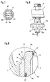
- FIG. 5 to 8 is another embodiment for an inventive Shut-off valve with integrated emptying option for the assigned Outgoing line shown.
- a handwheel 13a is provided, which consists of an outer part 23a and a inner cover part 26a; the latter in turn has a housing attachment 28a with an end opening 29a.
- the outer part 23a and that inner part 26a of handwheel 13a are annular projections by snapping on the outer and inner edges rotatable with each other connected.
- the spindle 19a consists of the drain valve 16a a valve rod 41 which has the valve head 42 at its upper end and at their lower end they are tensile and compressive but freely rotatable in a foot 43 is held.
- the spindle 10a of the shut-off valve 1a has the valve head 42 of the drain valve 16a cooperating constriction 44 of the bore 15a on Valve head 11a on, in such a way that the closure body 42 in the closed State of the drain valve is flush with the surface of the valve head 11 (Fig. 5).
- the foot 43 of the spindle 19a of the drain valve 16a is approximately cup-like educated. It has a polygonal, for example hexagonal cross section, and is in the likewise hexagonal interior of the housing extension 28a rotatably, but inclined longitudinally.
- the foot 43 has one Internal thread 45, with which it is connected to a corresponding external thread at the bottom End of the spindle 10a of the shut-off valve 1a can be screwed on and points in its Bottom part has an opening 46 which is penetrated by the valve rod 41.
- the valve rod 41 is tensile and pressure-resistant, for example by an outside in an annular groove inserted snap ring 47 connected to the foot 43.
- Fig. 5 shows the shut-off valve 1a in the open and the drain valve 16a in 6, the shut-off valve 1a in the closed and that Drain valve 16a in the open position.
- the foot 43 which is of nut-like design overall, has in its lower region mutually opposite side cutouts. Through these millings Opposite windows 49 are formed, through which the from the Leaving outgoing water flowing out and through the opening 29a can flow out in the housing projection 28a (FIG. 7). The water jet is exiting indicated at 50 in FIG. 8.
- FIG. 5 An enlarged view of the seals between the head 42 of the Valve rod 41 and the valve head 11a on the one hand and between this and 9 shows the pipe socket projecting into the distributor pipe 2 as detail X in Fig. 5.
- the for the longitudinal displacement of the valve spindle 10a of the Shut-off valve 1a required gap between the outer surface of the valve stem 10a and the spindle guide on the lower valve part 4 can be made in a manner known per se be sealed by sealing rings 51. Since the shut-off valve 1a but during the longest time the distributor device is in operation, i.e. of Water is applied, it makes sense to have one in the upper area of this gap provide additional seal.
- valve head 11a of the shut-off valve 1a provided on the back with a thickening 52, one to the cylindrical
- the outer surface of the valve spindle 19a forms an inclined sealing surface 53.
- This oblique sealing surface 53 interacts with a sealing edge 54 which is on a step-like recess 55 on the upper inner edge of the pipe socket 56 is formed, the part of the valve lower part protruding into the distributor pipe 2 4 forms and on which the spindle guide is formed.
- This metallic Seal is the gap between the spindle 10a and the spindle guide in Pipe socket 56 sealed at the upper end; this can avoid that waterstone forms in the gap and there is a risk that the Spindle becomes stiff or even stuck over time.
Landscapes
- Engineering & Computer Science (AREA)
- General Engineering & Computer Science (AREA)
- Mechanical Engineering (AREA)
- Chemical & Material Sciences (AREA)
- Thermal Sciences (AREA)
- Combustion & Propulsion (AREA)
- Physics & Mathematics (AREA)
- Multiple-Way Valves (AREA)
- Devices For Dispensing Beverages (AREA)
- Lift Valve (AREA)
- Nozzles (AREA)
- Mechanically-Actuated Valves (AREA)
- Sanitary Device For Flush Toilet (AREA)
Applications Claiming Priority (4)
| Application Number | Priority Date | Filing Date | Title |
|---|---|---|---|
| DE20011693U | 2000-07-05 | ||
| DE20011693 | 2000-07-05 | ||
| DE20014320U DE20014320U1 (de) | 2000-07-05 | 2000-08-19 | Vorrichtung zum Verteilen von Flüssigkeiten, insbesondere Wasser, bei Trink- und Brauchwasseranlagen, Warmwasser-Heizungsanlagen o.dgl. |
| DE20014320U | 2000-08-19 |
Publications (3)
| Publication Number | Publication Date |
|---|---|
| EP1170552A2 true EP1170552A2 (fr) | 2002-01-09 |
| EP1170552A3 EP1170552A3 (fr) | 2003-06-04 |
| EP1170552B1 EP1170552B1 (fr) | 2006-07-26 |
Family
ID=26056374
Family Applications (1)
| Application Number | Title | Priority Date | Filing Date |
|---|---|---|---|
| EP01115543A Expired - Lifetime EP1170552B1 (fr) | 2000-07-05 | 2001-06-28 | Dispositif de distribution de liquides |
Country Status (3)
| Country | Link |
|---|---|
| EP (1) | EP1170552B1 (fr) |
| AT (1) | ATE334349T1 (fr) |
| DE (1) | DE50110525D1 (fr) |
Cited By (2)
| Publication number | Priority date | Publication date | Assignee | Title |
|---|---|---|---|---|
| EP2053295A3 (fr) * | 2007-10-19 | 2013-08-07 | KERMI GmbH | Kit de contrôle |
| CN111684207A (zh) * | 2017-12-20 | 2020-09-18 | R.B.M.爱盒子有限责任公司 | 用于在特别地家用和/或工业类型的加热和/或冷却和/或调节网络中分配传热流体的收集器 |
Citations (4)
| Publication number | Priority date | Publication date | Assignee | Title |
|---|---|---|---|---|
| DE4030142A1 (de) * | 1990-09-24 | 1992-03-26 | Neheim Goeke & Co Metall | Heizungsventil |
| DE19652117C1 (de) * | 1996-12-14 | 1998-04-16 | Heimeier Gmbh Metall Theodor | Adapter-Armatur |
| DE29704960U1 (de) * | 1997-03-18 | 1998-04-16 | Reich Kg Regel & Sicherheits | Einstellvorrichtung |
| EP0903543A2 (fr) * | 1997-09-18 | 1999-03-24 | Dumser Metallbau GmbH & Co. KG | Distributeur d'un circuit rempli de fluide d'une installation de chauffage ou de réfrigération |
-
2001
- 2001-06-28 EP EP01115543A patent/EP1170552B1/fr not_active Expired - Lifetime
- 2001-06-28 DE DE50110525T patent/DE50110525D1/de not_active Expired - Fee Related
- 2001-06-28 AT AT01115543T patent/ATE334349T1/de not_active IP Right Cessation
Patent Citations (4)
| Publication number | Priority date | Publication date | Assignee | Title |
|---|---|---|---|---|
| DE4030142A1 (de) * | 1990-09-24 | 1992-03-26 | Neheim Goeke & Co Metall | Heizungsventil |
| DE19652117C1 (de) * | 1996-12-14 | 1998-04-16 | Heimeier Gmbh Metall Theodor | Adapter-Armatur |
| DE29704960U1 (de) * | 1997-03-18 | 1998-04-16 | Reich Kg Regel & Sicherheits | Einstellvorrichtung |
| EP0903543A2 (fr) * | 1997-09-18 | 1999-03-24 | Dumser Metallbau GmbH & Co. KG | Distributeur d'un circuit rempli de fluide d'une installation de chauffage ou de réfrigération |
Cited By (2)
| Publication number | Priority date | Publication date | Assignee | Title |
|---|---|---|---|---|
| EP2053295A3 (fr) * | 2007-10-19 | 2013-08-07 | KERMI GmbH | Kit de contrôle |
| CN111684207A (zh) * | 2017-12-20 | 2020-09-18 | R.B.M.爱盒子有限责任公司 | 用于在特别地家用和/或工业类型的加热和/或冷却和/或调节网络中分配传热流体的收集器 |
Also Published As
| Publication number | Publication date |
|---|---|
| EP1170552A3 (fr) | 2003-06-04 |
| ATE334349T1 (de) | 2006-08-15 |
| DE50110525D1 (de) | 2006-09-07 |
| EP1170552B1 (fr) | 2006-07-26 |
Similar Documents
| Publication | Publication Date | Title |
|---|---|---|
| WO2017118583A1 (fr) | Robinetterie à soupapes servant à remplir un réservoir de chasse sanitaire et réservoir de chasse sanitaire muni de ladite robinetterie à soupape | |
| EP0681675B1 (fr) | Raccord adaptateur de tuyauterie permettant le raccordement selectif d'un corps de chauffe | |
| EP0139808B1 (fr) | Dispositif d'actionnement à distance de deux ou plusieurs valves de vidange pour éviers, lavabos ou semblables | |
| EP3613908B1 (fr) | Procédé de montage d'un corps à encastrer | |
| DE4108458C2 (de) | Sanitärarmatur | |
| EP1170552B1 (fr) | Dispositif de distribution de liquides | |
| EP2634317B1 (fr) | Armature sanitaire | |
| DE19510670C2 (de) | Wasserführende Sanitärarmatur | |
| DE3700927C2 (fr) | ||
| EP1435480B1 (fr) | Robinetterie sanitaire | |
| WO1992015825A1 (fr) | Vanne de radiateur | |
| DE567158C (de) | Spuelventil | |
| DE2252395C3 (de) | Umschalter für ein System Wanne-Brause | |
| DE19603254C2 (de) | Ventil-Anbohrarmatur für unter Mediendruck stehende Rohrleitungen | |
| EP0250875B1 (fr) | Dispositif pour rincer des conduites de distribution de liquides, en particulier conduites d'eau | |
| DE19613391A1 (de) | Spritzdüse für Hochdruckreiniger | |
| DE10312863A1 (de) | Brausenanordnung | |
| DE2156457C3 (de) | Armatur für einen Heißwasserbereiter | |
| DE3243268A1 (de) | Wassermischhahn | |
| EP0090080A1 (fr) | Poignée de chalumeau avec ensemble de vannes | |
| DE4105436A1 (de) | Sanitaere wandarmatur | |
| DE1294609B (de) | Bruehvorrichtung fuer Kaffeemaschinen | |
| DE8004466U1 (de) | Vorrichtung zur Wasserverteilung, insbesondere für Heizungsanlagen | |
| DE2160339A1 (de) | Armatur fuer heisswasserbereiter | |
| DE19739944A1 (de) | Handabschaltpistole mit Druck-Mengenregulierung |
Legal Events
| Date | Code | Title | Description |
|---|---|---|---|
| PUAI | Public reference made under article 153(3) epc to a published international application that has entered the european phase |
Free format text: ORIGINAL CODE: 0009012 |
|
| AK | Designated contracting states |
Kind code of ref document: A2 Designated state(s): AT BE CH CY DE DK ES FI FR GB GR IE IT LI LU MC NL PT SE TR |
|
| AX | Request for extension of the european patent |
Free format text: AL;LT;LV;MK;RO;SI |
|
| PUAL | Search report despatched |
Free format text: ORIGINAL CODE: 0009013 |
|
| AK | Designated contracting states |
Designated state(s): AT BE CH CY DE DK ES FI FR GB GR IE IT LI LU MC NL PT SE TR |
|
| AX | Request for extension of the european patent |
Extension state: AL LT LV MK RO SI |
|
| RIC1 | Information provided on ipc code assigned before grant |
Ipc: 7F 24D 19/10 B Ipc: 7F 24D 3/10 A Ipc: 7F 16L 41/03 B |
|
| 17P | Request for examination filed |
Effective date: 20030712 |
|
| 17Q | First examination report despatched |
Effective date: 20030922 |
|
| AKX | Designation fees paid |
Designated state(s): AT CH DE GB LI |
|
| RAP1 | Party data changed (applicant data changed or rights of an application transferred) |
Owner name: WATTS INDUSTRIES DEUTSCHLAND GESELLSCHAFT MIT BESC |
|
| GRAP | Despatch of communication of intention to grant a patent |
Free format text: ORIGINAL CODE: EPIDOSNIGR1 |
|
| GRAS | Grant fee paid |
Free format text: ORIGINAL CODE: EPIDOSNIGR3 |
|
| GRAA | (expected) grant |
Free format text: ORIGINAL CODE: 0009210 |
|
| AK | Designated contracting states |
Kind code of ref document: B1 Designated state(s): AT CH DE GB LI |
|
| REG | Reference to a national code |
Ref country code: GB Ref legal event code: FG4D Free format text: NOT ENGLISH |
|
| REG | Reference to a national code |
Ref country code: CH Ref legal event code: EP |
|
| REF | Corresponds to: |
Ref document number: 50110525 Country of ref document: DE Date of ref document: 20060907 Kind code of ref document: P |
|
| REG | Reference to a national code |
Ref country code: CH Ref legal event code: NV Representative=s name: PATENTANWAELTE SCHAAD, BALASS, MENZL & PARTNER AG |
|
| GBT | Gb: translation of ep patent filed (gb section 77(6)(a)/1977) |
Effective date: 20061026 |
|
| PLBE | No opposition filed within time limit |
Free format text: ORIGINAL CODE: 0009261 |
|
| STAA | Information on the status of an ep patent application or granted ep patent |
Free format text: STATUS: NO OPPOSITION FILED WITHIN TIME LIMIT |
|
| 26N | No opposition filed |
Effective date: 20070427 |
|
| PGFP | Annual fee paid to national office [announced via postgrant information from national office to epo] |
Ref country code: CH Payment date: 20080624 Year of fee payment: 8 |
|
| PGFP | Annual fee paid to national office [announced via postgrant information from national office to epo] |
Ref country code: AT Payment date: 20080620 Year of fee payment: 8 |
|
| PGFP | Annual fee paid to national office [announced via postgrant information from national office to epo] |
Ref country code: DE Payment date: 20080521 Year of fee payment: 8 |
|
| PGFP | Annual fee paid to national office [announced via postgrant information from national office to epo] |
Ref country code: GB Payment date: 20080624 Year of fee payment: 8 |
|
| REG | Reference to a national code |
Ref country code: CH Ref legal event code: PL |
|
| GBPC | Gb: european patent ceased through non-payment of renewal fee |
Effective date: 20090628 |
|
| PG25 | Lapsed in a contracting state [announced via postgrant information from national office to epo] |
Ref country code: LI Free format text: LAPSE BECAUSE OF NON-PAYMENT OF DUE FEES Effective date: 20090630 Ref country code: CH Free format text: LAPSE BECAUSE OF NON-PAYMENT OF DUE FEES Effective date: 20090630 |
|
| PG25 | Lapsed in a contracting state [announced via postgrant information from national office to epo] |
Ref country code: GB Free format text: LAPSE BECAUSE OF NON-PAYMENT OF DUE FEES Effective date: 20090628 |
|
| PG25 | Lapsed in a contracting state [announced via postgrant information from national office to epo] |
Ref country code: AT Free format text: LAPSE BECAUSE OF NON-PAYMENT OF DUE FEES Effective date: 20090628 Ref country code: DE Free format text: LAPSE BECAUSE OF NON-PAYMENT OF DUE FEES Effective date: 20100101 |