EP1170544A2 - Dreidimensionale dekorative Lampenanordnung - Google Patents
Dreidimensionale dekorative Lampenanordnung Download PDFInfo
- Publication number
- EP1170544A2 EP1170544A2 EP00121182A EP00121182A EP1170544A2 EP 1170544 A2 EP1170544 A2 EP 1170544A2 EP 00121182 A EP00121182 A EP 00121182A EP 00121182 A EP00121182 A EP 00121182A EP 1170544 A2 EP1170544 A2 EP 1170544A2
- Authority
- EP
- European Patent Office
- Prior art keywords
- positioning
- frame rods
- recesses
- decorative lamp
- dimensional decorative
- Prior art date
- Legal status (The legal status is an assumption and is not a legal conclusion. Google has not performed a legal analysis and makes no representation as to the accuracy of the status listed.)
- Withdrawn
Links
- 238000004806 packaging method and process Methods 0.000 description 5
- 238000003780 insertion Methods 0.000 description 2
- 230000037431 insertion Effects 0.000 description 2
- 241000191291 Abies alba Species 0.000 description 1
- 240000006240 Linum usitatissimum Species 0.000 description 1
- 230000002411 adverse Effects 0.000 description 1
- 230000000712 assembly Effects 0.000 description 1
- 238000000429 assembly Methods 0.000 description 1
- 230000009286 beneficial effect Effects 0.000 description 1
- 239000013078 crystal Substances 0.000 description 1
- 238000002347 injection Methods 0.000 description 1
- 239000007924 injection Substances 0.000 description 1
- 238000012856 packing Methods 0.000 description 1
- 239000007787 solid Substances 0.000 description 1
Images





Classifications
-
- F—MECHANICAL ENGINEERING; LIGHTING; HEATING; WEAPONS; BLASTING
- F21—LIGHTING
- F21V—FUNCTIONAL FEATURES OR DETAILS OF LIGHTING DEVICES OR SYSTEMS THEREOF; STRUCTURAL COMBINATIONS OF LIGHTING DEVICES WITH OTHER ARTICLES, NOT OTHERWISE PROVIDED FOR
- F21V17/00—Fastening of component parts of lighting devices, e.g. shades, globes, refractors, reflectors, filters, screens, grids or protective cages
- F21V17/007—Fastening of component parts of lighting devices, e.g. shades, globes, refractors, reflectors, filters, screens, grids or protective cages with provision for shipment or storage
-
- A—HUMAN NECESSITIES
- A47—FURNITURE; DOMESTIC ARTICLES OR APPLIANCES; COFFEE MILLS; SPICE MILLS; SUCTION CLEANERS IN GENERAL
- A47G—HOUSEHOLD OR TABLE EQUIPMENT
- A47G33/00—Religious or ritual equipment in dwelling or for general use
- A47G33/04—Christmas trees
- A47G33/06—Artificial Christmas trees
-
- B—PERFORMING OPERATIONS; TRANSPORTING
- B44—DECORATIVE ARTS
- B44C—PRODUCING DECORATIVE EFFECTS; MOSAICS; TARSIA WORK; PAPERHANGING
- B44C5/00—Processes for producing special ornamental bodies
-
- F—MECHANICAL ENGINEERING; LIGHTING; HEATING; WEAPONS; BLASTING
- F21—LIGHTING
- F21S—NON-PORTABLE LIGHTING DEVICES; SYSTEMS THEREOF; VEHICLE LIGHTING DEVICES SPECIALLY ADAPTED FOR VEHICLE EXTERIORS
- F21S4/00—Lighting devices or systems using a string or strip of light sources
- F21S4/20—Lighting devices or systems using a string or strip of light sources with light sources held by or within elongate supports
Definitions
- the present invention relates to a three-dimensional decorative Lamp arrangement with a plurality of lamps in a three-dimensional manner are arranged, and in particular on a three-dimensional decorative Lamp assembly, which in its initial state is folded for packaging can be or from this initial state by the user himself can be pulled apart so that a three-dimensional arrangement is created.
- Conventional three-dimensional spherical decorative lamp assemblies have the shape of a sphere and consist of a plurality of semi-circular frame rods in connection with upper and lower positioning disks to form the shape of a sphere, with a plurality of lamps with lamp sockets being mounted on the side edge of each of the semi-circular frame rods can.
- the upper and lower positioning disks are usually firmly connected to one another, ie they are balls when they are sent from the factory.
- such a spherical decorative lamp with a solid shape takes up a larger volume, which leads to greater difficulties in transportation and packaging and thus causes higher costs. It is also more uncomfortable for the seller to set up, as is the home transport after the purchase for the buyer.
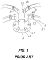
- the spherical decorative lamp in the U.S. patent includes an upper and a lower receiving seat A and a plurality of Frame rods B for attaching the lamps.
- a plurality of clamping gaps A1 are provided, the number of frame bars B correspond and with a plurality of enlarged chambers A2 in their rear Sections are provided.
- the frame rods B are in one piece at one end provided with a connecting end B2 and with a clamp seat B1 on its shaft to clamp the lamps (not shown).
- the frame rods B can with their Connection ends B2 in the enlarged chambers A2 of a receiving seat A pressed in and clamped by the clamping gaps A1.
- the structural elements of the spherical decorative lamp can be easily disassembled, which makes packing a small one Volume arises, which leads to a multitude of parts that the buyer himself must put together, d. H. he must arrange the lamps and the frame rods B connect to the receiving seats A, which is time consuming.
- a spherical decorative lamp that remains assembled and foldable, e.g. B. of the type 2128 called Crystal ball from the Minami International Co. overlap with this decorative lamp the ends of a plurality of frame rods and there will be several Linking axles used to make a pivot connection for the frame bars in to deliver different heights, which means all frame bars around the Swivel axis can be pulled apart or folded together. Since the Frame bars are at different heights, there is such a design a spherical decorative lamp, however, hardly gives the impression of a real ball and is therefore not particularly aesthetic. In addition, the frame bars when swiveling on the different heights not exactly in their desired Position to be attached, which once again adversely affects the Has aesthetics of the entire sphere.
- a user buys this item, he can use it conveniently and turn quickly and put in a second state by the frame rods and the upper and lower positioning disks are pressed into position and form a three-dimensional shape. The whole thing becomes storage again folded.
- the frame bars are on their top and bottom Provide ends with supports that have pins. These pens come with elastic Provide hook ends and positioning flanges are each at a certain distance arranged from their corresponding elastic hook ends.
- the top and bottom Positioning discs are provided with a plurality of open chambers, which in their number corresponds to the frame rods, these open chambers in the Close to their inner ends are provided with through holes, each one Have a diameter that is smaller than that of the corresponding pins.
- the lower elastic hook ends of the pins of the upper and lower positioning discs fit through the through holes so that the shafts of the pins between the elastic Hook ends and the flanges movable with the top and bottom Positioning disks can be connected in the initial state.
- the frame rods can be the desired lamp arrangement for occupy a plurality of three-dimensionally arranged lamps.
- the frame bars mentioned above can take the form of semicircles with others have arcuate sections or they can take the form of successive have inclined sections, creating three-dimensional decorative lamps with various forms can be formed.
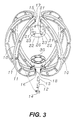
- the spherical lamp assembly comprises FIG present invention, a plurality of frame rods 10, an upper Positioning disk 20 and a lower positioning disk 30.
- a plurality of frame rods 10 In the one shown in FIG Embodiment six semicircular frame rods 10 are present and in the same distance from each other so that a ball is formed.
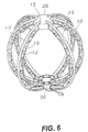
- the frame bars 10 in this embodiment are semicircular and one A plurality of connection holes 11 are thereon for fixing lamps 13 with Lamp sockets 12 are provided.
- any Connection hole 11 are previously provided with a connector 14, wherein the connector 14 with an insertion portion for insertion into a hole 11 is provided, and a lamp holder 12 can then with a through hole of the Connector 14 are connected.
- Lamps 13 can of course also in other ways with the frame rods 10th get connected.
- each of the frame rods 10 are each provided with supports 15, 16, each of which has a smaller thickness and width than that of the frame rod 10.
- the supports 15, 16 are extended in one piece, so that pins 17, 18 with the same Form are formed.
- the shafts of the pins 17, 18 have suitable diameters and their ends 171, 181 are tapered with diameters slightly larger than those of the shafts, and are each with a central gap 172 (182) and with one provided elastic hook end.
- a positioning flange 173 (183) is provided somewhat spaced from the corresponding conical end 171 (181).
- the upper and lower positioning disks 20, 30 are both made of plastic. They will now be described using the positioning disc 20 as an example.
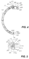
- the positioning disk 20 is provided near its edge with a plurality of depressions 21 in a number which corresponds to that of the frame rods 10; the depth of each of the recesses 21 is half that of the positioning disc 20.
- the inner bottom surface 22 of the recess 21 is provided with a through hole 23 which extends through the positioning disc 20, the diameter of the through hole 23 is slightly larger than that of the pins 17 (18).
- a hollow tube 24 is formed and has an inner hole 25 which communicates with the through hole 22.
- the diameter of the inner hole 25 is slightly larger than that of the through hole 23, so that a shoulder section 26 (see FIG. 5) is formed.
- frame rods 100 are each provided with an upper portion 101 with a smaller diameter and a lower portion 102 with a larger diameter.
- Such frame rods 100 can be injection molded separately like the frame rods 10 already mentioned.
- the frame rods 103 are provided with successive inclined portions 104, 105, 106, etc., and are connected to the upper and lower positioning plates 20, 30 so that a three-dimensional decorative lamp arrangement in the shape of a Christmas tree is formed.
- the frame rods in the main elements of the three-dimensional decorative lamp assembly of the present invention can be connected to the upper and lower positioning disks to form an overall unit, whereby the three-dimensional decorative lamp assembly can be folded into a smaller overall volume, which has advantages in packaging, transportation and Storage leads.
- a connection of the frame rods with the upper and lower positioning disks in the initial state also makes assembly easier for the user.
Landscapes
- Engineering & Computer Science (AREA)
- General Engineering & Computer Science (AREA)
- Packaging Frangible Articles (AREA)
- Fastening Of Light Sources Or Lamp Holders (AREA)
- Illuminated Signs And Luminous Advertising (AREA)
Abstract
Description
Bei kugelförmigen dekorativen Lampen sind die oberen und unteren Positionierscheiben meistens fest miteinander verbunden, d. h. es sind schon Kugeln, wenn sie aus der Fabrik verschickt werden. Eine solche kugelförmige dekorative Lampe mit einer festen Form beansprucht jedoch ein größeres Volumen, was zu größeren Schwierigkeiten beim Transport und bei der Verpackung führt und somit höhere Kosten verursacht. Auch für den Verkäufer ist das Aufstellen unbequemer, ebenso für den Käufer der Heimtransport nach dem Kauf.
- Fig. 1
- ist eine Schrägansicht einer herkömmlichen kugelförmigen Lampenanordnung;
- Fig. 2
- ist eine Schrägansicht einer ersten bevorzugten Ausführungsform der vorliegenden Erfindung, wobei die vorliegende Erfindung zu einer Kugel zusammengebaut worden ist;
- Fig. 3
- ist eine Schrägansicht und zeigt die wesentlichen Elemente der vorliegenden Erfindung;
- Fig. 4
- ist eine teilweise vergrößerte ebene Ansicht und zeigt eine einzelne Rahmenstange und eine einzelne Positionierscheibe der vorliegenden Erfindung im Ausgangszustand mit einem Verbindungsbereich zwischen diesen beiden;
- Fig. 5
- ist eine weitere teilweise ebene Ansicht und zeigt den Verbindungsbereich aus Fig. 4;
- Fig. 6
- ist eine Schrägansicht und zeigt die bevorzugte Ausführungsform aus Fig. 2 mit einer Mehrzahl darauf angebrachter Lampen mit Lampenfassungen;
- Fig. 7
- ist eine Vorderansicht von Fig. 6;
- Fig. 8
- ist eine Draufsicht auf Fig. 7;
- Fig. 9
- ist eine Vorderansicht und zeigt die erste bevorzugte Ausführungsform der Erfindung in ihrem Ausgangszustand und flach zusammengefaltet;
- Fig. 10
- ist eine Draufsicht auf Fig. 9;
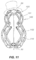
- Fig. 11
- ist eine Schrägansicht einer zweiten bevorzugten Ausführungsform der vorliegenden Erfindung;
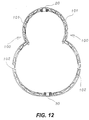
- Fig. 12
- ist eine Querschnittsansicht von Fig. 11;
- Fig. 13
- ist eine Schrägansicht einer dritten bevorzugten Ausführungsform der vorliegenden Erfindung;
- Fig. 14
- ist eine Querschnittsansicht von Fig. 13.
Unter Bezugnahme auf Fig. 3 und 4 bestehen die oberen und unteren Positionierscheiben 20, 30 beide aus Plastik. Sie werden nun beschrieben, indem die Positionierscheibe 20 als Beispiel dient. Die Positionierscheibe 20 ist in der Nähe ihres Randes mit einer Mehrzahl von Vertiefungen 21 in einer solchen Anzahl versehen, die derjenigen der Rahmenstangen 10 entspricht; die Tiefe jeder der Vertiefungen 21 ist halb so groß wie die der Positionierscheibe 20. Die innere Bodenfläche 22 der Vertiefung 21 ist mit einem Durchgangsloch 23 versehen, das sich durch die Positionierscheibe 20 erstreckt, der Durchmesser des Durchgangsloches 23 ist etwas größer als derjenige der Stifte 17 (18). Auf der anderen Seite der Bodenfläche 22 der Vertiefung 21 ist ein Hohlrohr 24 gebildet und hat ein Innenloch 25, das mit dem Durchgangsloch 22 in Verbindung steht. Der Durchmesser des Innenloches 25 ist etwas größer als derjenige des Durchgangsloches 23, so dass ein Schulterabschnitt 26 (siehe Fig. 5) gebildet wird.
Die Rahmenstangen in den Hauptelementen der dreidimensionalen dekorativen Lampenanordnung der vorliegenden Erfindung können mit den oberen und unteren Positionierscheiben verbunden werden, so dass eine Gesamteinheit gebildet wird, wodurch die dreidimensionale dekorative Lampenanordnung zu einem kleineren Gesamtvolumen gefaltet werden kann, was zu Vorteilen bei Verpackung, Transport und Lagerung führt.
Eine Verbindung der Rahmenstangen mit den oberen und unteren Positionierscheiben im Ausgangszustand erleichtert dem Benutzer auch den Zusammenbau.
Claims (7)
- Dreidimensionale dekorative Lampenanordnung mit einer Mehrzahl von Rahmenstangen und einer oberen Positionierscheibe und einer unteren Positionierscheibe zum Verbinden der Rahmenstangen,
wobei
die Rahmenstangen eine Mehrzahl von darauf befestigten Lampen tragen und die oberen und unteren Positionierscheiben eine identische Form, allerdings mit gegensätzlichen Orientierungen, haben und mit einer Mehrzahl von Vertiefungen in derselben Anzahl versehen sind wie diejenige der Rahmenstangen, wobei die innere Bodenfläche jeder der Vertiefungen mit einem Durchgangsloch versehen ist, das sich durch die entsprechende Positionierscheibe erstreckt, wobei jede Rahmenstange mit oberen und unteren Enden versehen ist, die eine Stütze tragen, deren Verlängerung einstückig einen Stift bildet, wobei die Stifte und die Vertiefungen in einem Ausgangszustand jeweils schwenkbar miteinander verbunden sind und in einem zweiten Zustand zum Positionieren durch Pressen jeweils fest miteinander verbunden sind. - Dreidimensionale dekorative Lampenanordnung nach Anspruch 1,
wobei,
die Stützen an den unteren und oberen Enden der Rahmenstangen jeweils eine geringere Dicke und Breite haben als die Rahmenstangen und wobei die Stützen nicht vollständig herabgepresst werden, jedoch über die Oberfläche der unteren und oberen Positionierscheiben, damit sie zum Zusammenfalten gedreht werden können, wenn sie im Ausgangszustand schwenkbar miteinander verbunden sind. - Dreidimensionale dekorative Lampenanordnung nach Anspruch 1,
wobei
die Stifte, die von den verlängerten Stützen auf den oberen und unteren Enden der Rahmenstangen gebildet werden, jeweils mit einem mittleren Spalt versehen sind, der etwas größer ist als der Schaft des Stiftes und zusammen mit einem konischen Ende ein gewünschtes elastisches Hakenende bildet, und wobei auf dem Schaft beabstandet vom konischen Ende ein Positionierflansch angeordnet ist. - Dreidimensionale dekorative Lampenanordnung nach Anspruch 3,
wobei
sich die konischen Enden der Stifte durch die entsprechenden Durchgangslöcher der Vertiefungen erstrecken und die Schäfte zwischen den konischen Enden und den Positionierflanschen als Schwenkachsen zum Schwenken in den Ausgangszustand verwenden. - Dreidimensionale dekorative Lampenanordnung nach Anspruch 4,
wobei
die Stifte weiter gepresst werden, so dass die Positionierflansche vollständig durch die Durchgangslöcher der Vertiefungen gedrückt werden und auf der anderen Seite der Durchgangslöcher in den zweiten Zustand des Positionierens durch Pressen geraten. - Dreidimensionale dekorative Lampenanordnung nach Anspruch 5,
wobei
die Stützen auf den Rahmenstangen vollständig in die Vertiefungen eingebracht sind, so dass sie eben mit den Oberflächen der oberen und unteren Positionierscheiben abschließen, wenn sie sich im zweiten Zustand des Positionierens durch Pressen befinden. - Dreidimensionale dekorative Lampenanordnung nach Anspruch 5,
wobei
die oberen und unteren Positionierscheiben unterhalb der Durchgangslöcher der Vertiefungen mit Hohlrohren versehen sind, die jeweils einen Durchmesser aufweisen, der größer ist als der der Durchgangslöcher, so dass ein Schulterabschnitt zum Stoppen der Positionierflansche gebildet wird..
Applications Claiming Priority (3)
| Application Number | Priority Date | Filing Date | Title |
|---|---|---|---|
| US09/610,371 US6386734B1 (en) | 2000-07-05 | 2000-07-05 | Three dimensional foldable decorative lamp structure |
| DE20011804U | 2000-07-07 | ||
| DE20011804U DE20011804U1 (de) | 2000-07-05 | 2000-07-07 | Dreidimensionale dekorative Lampenanordnung |
Publications (2)
| Publication Number | Publication Date |
|---|---|
| EP1170544A2 true EP1170544A2 (de) | 2002-01-09 |
| EP1170544A3 EP1170544A3 (de) | 2004-05-26 |
Family
ID=26056381
Family Applications (1)
| Application Number | Title | Priority Date | Filing Date |
|---|---|---|---|
| EP00121182A Withdrawn EP1170544A3 (de) | 2000-07-05 | 2000-09-29 | Dreidimensionale dekorative Lampenanordnung |
Country Status (3)
| Country | Link |
|---|---|
| US (1) | US6386734B1 (de) |
| EP (1) | EP1170544A3 (de) |
| DE (1) | DE20011804U1 (de) |
Cited By (1)
| Publication number | Priority date | Publication date | Assignee | Title |
|---|---|---|---|---|
| CN104822258A (zh) * | 2012-07-13 | 2015-08-05 | Ct集团香港控股有限公司 | 一种分体式物件 |
Families Citing this family (10)
| Publication number | Priority date | Publication date | Assignee | Title |
|---|---|---|---|---|
| US6386734B1 (en) * | 2000-07-05 | 2002-05-14 | Shining Blick Enterprises Co., Ltd. | Three dimensional foldable decorative lamp structure |
| GB2415770A (en) * | 2004-07-01 | 2006-01-04 | Jamie Barrett | A lamp sculpture |
| US8066405B2 (en) * | 2007-10-25 | 2011-11-29 | Simon Jerome H | Lumenairs having structurally and electrically integrated arrangements of quasi point light sources, such as LEDs |
| US8491147B1 (en) * | 2010-11-22 | 2013-07-23 | Thomas Bardash, Jr. | Method of presenting a Christmas star decoration |
| US8696160B2 (en) * | 2011-11-08 | 2014-04-15 | Cool Lumens | Modular LED lighting system |
| US8764234B1 (en) * | 2012-12-21 | 2014-07-01 | Donald V. Acree | Decorative sphere |
| CN105864700B (zh) * | 2015-01-23 | 2018-07-20 | 广东中筑天佑照明技术有限公司 | 一种景观灯 |
| CN105526559B (zh) * | 2016-01-29 | 2018-11-16 | 唐山坤达科技有限公司 | 一种led灯铝型材 |
| US10161601B1 (en) * | 2018-02-20 | 2018-12-25 | Zhu Hai Fu Yun Lighting Industrial Co., Ltd. | Collapsible decorative lamp |
| US12156600B1 (en) * | 2023-11-02 | 2024-12-03 | Kiss Nail Products, Inc. | Foldable wig stand |
Citations (1)
| Publication number | Priority date | Publication date | Assignee | Title |
|---|---|---|---|---|
| US5645343A (en) | 1996-09-13 | 1997-07-08 | Rinehimer; John C. | Light-string holder |
Family Cites Families (7)
| Publication number | Priority date | Publication date | Assignee | Title |
|---|---|---|---|---|
| DE2128898C3 (de) * | 1971-06-11 | 1980-02-07 | 8000 Muenchen | System zur variablen Anordnung geometrischer Grundfiguren und seine Verwendung |
| US5629057A (en) * | 1996-05-20 | 1997-05-13 | Toyo Electric Manufacturing Co. Ltd. | Collapsible lighted skeletal structure |
| US5876111A (en) * | 1996-09-04 | 1999-03-02 | Wu; Jeng-Shyong | Decorative lighting string with expandable, shrinkable and three-dimensional unit |
| US6070991A (en) * | 1998-11-17 | 2000-06-06 | Rumpel; Donald | Decorative light fixture |
| US6217192B1 (en) * | 1999-06-01 | 2001-04-17 | Linard S. Stratton | Decorative light string support |
| US6135617A (en) * | 1999-10-21 | 2000-10-24 | Lai; Wei-Cheng | Folding illumination skeleton |
| US6386734B1 (en) * | 2000-07-05 | 2002-05-14 | Shining Blick Enterprises Co., Ltd. | Three dimensional foldable decorative lamp structure |
-
2000
- 2000-07-05 US US09/610,371 patent/US6386734B1/en not_active Expired - Fee Related
- 2000-07-07 DE DE20011804U patent/DE20011804U1/de not_active Expired - Lifetime
- 2000-09-29 EP EP00121182A patent/EP1170544A3/de not_active Withdrawn
Patent Citations (1)
| Publication number | Priority date | Publication date | Assignee | Title |
|---|---|---|---|---|
| US5645343A (en) | 1996-09-13 | 1997-07-08 | Rinehimer; John C. | Light-string holder |
Cited By (1)
| Publication number | Priority date | Publication date | Assignee | Title |
|---|---|---|---|---|
| CN104822258A (zh) * | 2012-07-13 | 2015-08-05 | Ct集团香港控股有限公司 | 一种分体式物件 |
Also Published As
| Publication number | Publication date |
|---|---|
| US6386734B1 (en) | 2002-05-14 |
| DE20011804U1 (de) | 2000-09-28 |
| EP1170544A3 (de) | 2004-05-26 |
Similar Documents
| Publication | Publication Date | Title |
|---|---|---|
| DE69117921T2 (de) | Spielzeug das von einem Kind unabhängig zusammengesetzt werden kann | |
| DE3784317T2 (de) | Spielzeugbausatz fuer die konstruktion von baumaehnlichen modellen. | |
| DE60012314T2 (de) | Warenschaustand | |
| DE3876839T2 (de) | Stuhl- und wagenkombination. | |
| DE3782223T2 (de) | Behaelter-ordner fuer flache gegenstaende, insbesondere fuer datenverarbeitungsplatten. | |
| DE3129627A1 (de) | Traegeranordnung fuer einen sitz oder ein tragbettchen fuer ein baby zur bildung eines sport- oder kinderwagens | |
| DE2545490C3 (de) | Zusammenklappbarer Kinderwagen | |
| DE2746922A1 (de) | Klapptisch mit sperrscharnier | |
| DE20011804U1 (de) | Dreidimensionale dekorative Lampenanordnung | |
| DE202023100579U1 (de) | Gelenkvorrichtung und Zusammenklappbare Sternlampe | |
| DE8502579U1 (de) | Verwandelbares spielzeug | |
| DE20105458U1 (de) | Bewegliche Abschirmung | |
| DE602006000845T2 (de) | Fahrradrahmen | |
| DE10212623B4 (de) | Rollstuhl mit einem Handgriff, der zwischen zwei Positionen bewegbar ist, um den Einstieg in einen Sitz und den Ausstieg aus diesem zu erleichtern | |
| DE19609168C2 (de) | Zusammengesetzter Dekorationskörper, insbesondere Dekorationsstern, bestehend aus einem Trägerkörper und daran befestigten als pyramidenförmige Spitzen ausgebildeten Teilen und Verfahren zu dessen Herstellung | |
| DE69413075T2 (de) | Sitz- und Bettrahmen in Beziehung auf die variabel zu platzierende Rückenlehne rotierbar | |
| DE102008057274A1 (de) | Spielfigur für ein Tischfußballgerät | |
| DE3208314C2 (de) | ||
| DE19916556A1 (de) | Kreuzgelenk eines Bodenreinigungsgerätes | |
| DE20206740U1 (de) | Drehbare Steckdoseneinheit zum Einsetzen in eine Platte | |
| DE531856C (de) | Bauspiel, bei welchem ein den Koerperteil bildendes Rumpfstueck durch Anstecken von Gliedmassen und Koepfen zu einer Spielfigur ausgebildet werden kann | |
| DE2647561C2 (de) | ||
| DE20011562U1 (de) | Zusammenklappbarer Tretroller | |
| EP0612491A2 (de) | Ausstellungsstand für Fliesen | |
| EP0617204A1 (de) | Möbel mit einem aus zylindrischen Elementen zusammengesetzten Tragwerk |
Legal Events
| Date | Code | Title | Description |
|---|---|---|---|
| PUAI | Public reference made under article 153(3) epc to a published international application that has entered the european phase |
Free format text: ORIGINAL CODE: 0009012 |
|
| AK | Designated contracting states |
Kind code of ref document: A2 Designated state(s): AT BE CH CY DE DK ES FI FR GB GR IE IT LI LU MC NL PT SE |
|
| AX | Request for extension of the european patent |
Free format text: AL;LT;LV;MK;RO;SI |
|
| PUAL | Search report despatched |
Free format text: ORIGINAL CODE: 0009013 |
|
| AK | Designated contracting states |
Kind code of ref document: A3 Designated state(s): AT BE CH CY DE DK ES FI FR GB GR IE IT LI LU MC NL PT SE |
|
| AX | Request for extension of the european patent |
Extension state: AL LT LV MK RO SI |
|
| RIC1 | Information provided on ipc code assigned before grant |
Ipc: 7F 21W 121/00 B Ipc: 7F 21V 1/06 B Ipc: 7F 21V 17/00 B Ipc: 7A 47G 33/06 B Ipc: 7F 21S 4/00 A |
|
| STAA | Information on the status of an ep patent application or granted ep patent |
Free format text: STATUS: THE APPLICATION IS DEEMED TO BE WITHDRAWN |
|
| 18D | Application deemed to be withdrawn |
Effective date: 20040401 |