EP1168564A1 - Regler regelbarer Gleichspannung für einen trasformatorlosen Serienblindleistungskompensator - Google Patents
Regler regelbarer Gleichspannung für einen trasformatorlosen Serienblindleistungskompensator Download PDFInfo
- Publication number
- EP1168564A1 EP1168564A1 EP00107015A EP00107015A EP1168564A1 EP 1168564 A1 EP1168564 A1 EP 1168564A1 EP 00107015 A EP00107015 A EP 00107015A EP 00107015 A EP00107015 A EP 00107015A EP 1168564 A1 EP1168564 A1 EP 1168564A1
- Authority
- EP
- European Patent Office
- Prior art keywords
- voltage
- output
- current
- controller
- control
- Prior art date
- Legal status (The legal status is an assumption and is not a legal conclusion. Google has not performed a legal analysis and makes no representation as to the accuracy of the status listed.)
- Withdrawn
Links
Images


Classifications
-
- G—PHYSICS
- G05—CONTROLLING; REGULATING
- G05F—SYSTEMS FOR REGULATING ELECTRIC OR MAGNETIC VARIABLES
- G05F1/00—Automatic systems in which deviations of an electric quantity from one or more predetermined values are detected at the output of the system and fed back to a device within the system to restore the detected quantity to its predetermined value or values, i.e. retroactive systems
- G05F1/70—Regulating power factor; Regulating reactive current or power
-
- H—ELECTRICITY
- H02—GENERATION; CONVERSION OR DISTRIBUTION OF ELECTRIC POWER
- H02J—CIRCUIT ARRANGEMENTS OR SYSTEMS FOR SUPPLYING OR DISTRIBUTING ELECTRIC POWER; SYSTEMS FOR STORING ELECTRIC ENERGY
- H02J3/00—Circuit arrangements for ac mains or ac distribution networks
- H02J3/18—Arrangements for adjusting, eliminating or compensating reactive power in networks
- H02J3/1807—Arrangements for adjusting, eliminating or compensating reactive power in networks using series compensators
-
- Y—GENERAL TAGGING OF NEW TECHNOLOGICAL DEVELOPMENTS; GENERAL TAGGING OF CROSS-SECTIONAL TECHNOLOGIES SPANNING OVER SEVERAL SECTIONS OF THE IPC; TECHNICAL SUBJECTS COVERED BY FORMER USPC CROSS-REFERENCE ART COLLECTIONS [XRACs] AND DIGESTS
- Y02—TECHNOLOGIES OR APPLICATIONS FOR MITIGATION OR ADAPTATION AGAINST CLIMATE CHANGE
- Y02E—REDUCTION OF GREENHOUSE GAS [GHG] EMISSIONS, RELATED TO ENERGY GENERATION, TRANSMISSION OR DISTRIBUTION
- Y02E40/00—Technologies for an efficient electrical power generation, transmission or distribution
- Y02E40/30—Reactive power compensation
Definitions
- the invention relates to a controller for controlling a reactive series compensator serially inserted at compensator terminals into a power transmission line.
- an inverter control is performed in order to control the line current and/or the voltage applied from the compensator to the transmission line.
- the voltage/current control enables to control the power flow of power from one end to the other end of the transmission line and to perform a power flow into the inverter of the compensator in order to charge a capacitor which provides a compensator terminal output voltage at the compensator terminals.
- a current feedback control loop and a voltage feedback control loop are employed in order to respectively control the reactive and the active part of the line current.
- the modulation signal based on which the PWM control of the inverter is performed is a sinusoidal signal of a particular phase. Adjusting the amplitude and the phase of the modulation signal allows to perform the power control.
- the output voltage of the compensator can be controlled by a modulation index with a constant DC voltage.
- the output voltage can be controlled by the DC voltage only using a constant modulation index, as the paper by A. Beer, H. Stemmler, H. Okayama, "Hybride Transformerless Reactive Series Compensators", EPE 1999 - Lausanne describes (see page 8 of this paper).
- constant DC voltage the injection of harmonics into the transmission line by the inverter cannot be reduced even if the fundamental component is smaller than the DC voltage.
- constant modulation index control the controllability of the DC voltage is degraded in zero or very low DC voltage region since the active voltage cannot be sufficiently injected into the transmission line. Therefore, this method is not applicable to a full range operation.
- it is also difficult to reduce DC voltage dependent losses such as the switching loss of switching elements of the inverter and leakage loss of the DC capacitor of the compensator.
- the present invention in particular addresses the problem as to how the injection of harmonics by a compensator controlled by a controller including a current and voltage control loop can be reduced.
- the present invention also addresses the ether aforementioned problems.
- transformerless reactive series compensators and of controllers for controlling a compensator and comprising a current and voltage control loop will be described.
- a transformerless reactive series compensator is one of these equipments and is effective to perform a power flow control as was explained above. Since the transformerless reactive series compensator does not comprise the transformer its size is small and it can be advantageously used.
- Fig. 1a and 1b respectively show a typical configuration of a power transmission system comprising two AC power systems la, 1b coupled to each other through power transmission lines 2a, 2b having a respective inductance L AC and resistance R AC .
- the power transmission system may be a single phase system or a three-phase system. Whilst in the single phase system only one series compensator 3 need to be provided, in the three-phase system a plurality of series compensators 3 are respectively serially inserted as shown in Fig. 1b.
- Reference numerals 3a, 3b respectively show the terminals at which the respective series compensator (or compensators) are serially inserted.
- a typical series compensator 3 comprises a starting switch 4, a filter 12, an inverter 7, a DC capacitor C DC , a control means C, a saw-tooth generator 10 and a modulation signal generation means 11.
- the inverter 7 comprises four thyristors 5a, 5b, 5c, 5d respectively controlled by a PWM control signal SW 5a , SW 5b , SW 5c , SW 5d output by the control means C.
- thyristor is usually a device whose turn-off is not controllable, in Fig. 2, since a PWM is used for the inverter, a gate turn-off type thyristor is employed. Since a GTO (gate turn-off thyristor), a GCT (gate commutated thyristor) and an IGBT (insulated gate bipolar transistor) are also generally be possible for operating as the kind of switching power device in Fig. 2, hereinafter it is assumed that the expression “thyristor” comprises all such switching power devices.
- Each thyristor has connected anti-parallely thereto a diode 6a, 6b, 6c, 6d.
- the filter 12 comprises two reactors 9b, 9a. and a capacitor 8 for filtering higher order harmonics which are generated by the PWM control of the inverter 7.
- the filter terminals are connected to the respective interconnections of the thyristors 5a, 5b and of the diodes 6a, 6b and the thyristors 5c, 5d and the diodes 6c, 6d.
- the DC capacitor C DC is connected at the other terminals of the thyristors and the diodes.
- the circuit configuration of the series compensator 3 is conventional and is for example described in the European patent applications No. 98 116 096.3, No. 98 106 780.4 and No. 99 124 851.9 by the same applicant. These patent applications in particular describe the start and stop control of the series compensator 3 and a decoupling control.
- a PWM control of the inverter 7 is carried out as principally shown in the diagram of Fig. 3.
- a modulation signal generation means 11 in Fig. 2 generates a sinusoidal modulation signal m and the saw-tooth generator 10 outputs two saw-tooth carrier signals csl, cs2.
- a PWM control signal SW 5a , SW 5d is generated by comparing the modulation signal m with the respective carrier signal csl, cs2. That is, when the modulation signal amplitude is larger than the carrier signal csl amplitude then the PWM switching signal SW 5a is on and it is off if the modulation signal amplitude is smaller.
- the other PWM switching signal SW 5d is switched from ON to OFF.
- the PWM signals SW 5a , SW 5d are used to trigger the thyristor 5a, 5d. It should be noted that of course a similar control applies to the thyristors 5b, 5c which is however not described here for simplicity.
- the output voltage u c at the connection terminals 3a, 3d will have a waveform as shown in Fig. 3 in the bottom graph. It will be appreciated that by changing the respective amplitudes of the modulation signal and/or the carrier signal and/or by changing the phase of the modulation signal and/or the carrier signal, different waveforms of the output voltage u c (hereinafter also called the inverter terminal voltage or compensator output voltage) can be achieved. Comparing Fig. 3 with Fig. 2 it can be seen that essentially the output voltage u c is the voltage applied to the terminal 3a, 3b.
- Fig. 4a shows a summary diagram of the essential parts of Fig. 2 necessary for explaining the current and voltage control.
- Fig. 4b shows the principle phasor diagram for Fig. 4a.
- the compensator 3 is serially connected between the power transmission lines 2a, 2b which are connected to the AC power systems 1a, 1b.
- the line impedance R AC For the purpose of explaining the current and the voltage control with respect to their phase relationships it is not necessary to consider explicitly the line impedance R AC , although it should be understood that of course the line impedance R AC is also present in Fig. 4a.
- the inverter control is schematically illustrated with the block to which the reference numeral 7 has been attached.
- a modulation signal m is applied in order to perform the PWM control.
- u L is the voltage occurring as a result of the line impedance L AC
- i is the line current
- i DC is the current flowing through the DC capacitor C DC
- u DC is the voltage over the DC capacitor C DC
- u c is the output voltage of the series compensator 3.
- u x is the overhead voltage which is a difference voltage between the AC sources.
- the leakage conductance in the DC side which could include the switching losses, leakage losses of capacitors and/or losses of DC filters (essentially a parallel resistance to the DC capacitor C DC is not necessary to be considered for the phase relationships.
- Fig. 4b shows a principle phasor diagram and the voltages explained with reference to Fig. 4a are shown therein.
- the compensator 3 can output an output voltage u c of arbitrary phase with limited amplitude using the DC capacitor voltage u DC .
- Fig. 5(a), 5(b) and Fig. 5(c) respectively show the cases for no compensation, capacitive operation and inductive operation when controlling the line current i. That is, when the compensator 3 injects a zero voltage u c into the line, then the inductance voltage u L is the same as the overhead voltage u x (Fig. 5(a)). In this case, the line current i flows through the transmission line with a 90° phase lag with respect the inductance voltage u L .
- the compensator 3 injects an inductive voltage to the line (u c is in-phase with the inductance voltage u L ), the inductance voltage u L is decreased and therefore also the line current i is decreased (Fig.5(c)).
- the first purpose of the compensator 3 is that the line current i can be controlled (increased/decreased) by the voltage (by the amplitude and the phase of the compensator output voltage u c ) output by the compensator 3.
- control in Fig. 5 can only be carried out if the DC capacitor C DC has been charged to the predetermined voltage u DC since otherwise no injection of voltage would be possible into the line.
- Such a charging or active power flow from the line to the capacitor is explained with reference to Fig. 6 and Fig. 7.
- a charging of the DC capacitor C DC requires an active power flow from the transmission lines 2a, 2b to the DC capacitor C DC through the inverter 7.
- the compensator 3 has to feed the active component of the applied AC voltage u c to the DC capacitor C DC .
- the compensator 3 In steady state conditions, as already explained with reference to Fig. 5(c) and as shown also in Fig. 6(a), the compensator 3 outputs a reactive voltage u c which has a 90° difference phase to the line current i. This situation is present in the initial state and the final state of charge control as shown with Fig. 6(a) and 6(c).
- the transient inductance voltage includes a di/dt component and a ⁇ Li component.
- the di/dt component is generated, the ⁇ Li component is influenced.
- the variation of the ⁇ Li component influences the di/dt component and the line current fluctuates in an oscillation manner as shown in Fig. 6(b). Consequently, the charging process does not only influence the capacitor voltage but also the line current.
- the reason is the coupling effect through the line inductance L AC as can be understood from considering the dynamic behaviour of the currents and voltages.
- L AC (di/dt) u AC
- L AC , i and u AC are the line inductance, a line current and the inductance voltage.
- the line current has a fluctuation and an active component which is a in-phase component to the compensator voltage.
- This active component now causes an active power flow from the power transmission line to the DC capacitor C DC in the transient state as shown in Fig. 7(b).
- the line current is controlled, obviously also the DC voltage is influenced by the line current control.
- a controller for the series compensator is to perform a control to increase/decrease the line current as shown in Fig. 5 and to charge the DC capacitor C DC by allowing an active power flow to the DC capacitor C DC as in Fig. 6, 7.
- Such controllers will be explained hereinafter.
- Fig. 8 and Fig. 9 show controllers for a single phase and three-phase system, respectively.
- Such controllers comprising essentially a current loop and a voltage loop are known from "Hybrid transformerless reactive series compensators" Proceedings of the 8th European Conference on Power Electronics and Applications Conference (EPE) - Lausanne 1999, pages 1-10.
- EPE Power Electronics and Applications Conference
- the series compensator 3 has the configuration as already explained above with respect to Fig. 2 or 4. It is connected serially into the power transmission lines 2a, 2b at the compensator terminals 3a, 3b.
- the compensator 3 is controlled by a modulation signal m.
- a current sensor 24 senses the line current i and a voltage sensor 26 senses the DC capacitor voltage u DC .
- Equations (2.7) and (2.8) respectively describe the current dynamics.
- the DC voltage dynamics in equation (2.2) can be related to the AC current dynamics using a balance of power on the AC and DC side.
- equations (2.12) and (2.13) show that the AC current (i d and iq) and the DC voltage (u DC ) can indeed be controlled via the modulation signal (m d and m q ), that is via the modulation indexes m d and m q . Also equation (2.16) shows that this is possible.
- Fig. 8 shows a block diagram of a basic control of the series compensator.
- This controller consists of the current controller 20 with the amplitude detector 21, the DC voltage controller 16 with the filter 15, the current phase detector (PLL) 18, the coordinate transformation unit 14 and the compensation of a DC voltage fluctuation by the DC voltage fluctuation compensation means 13.
- PLL current phase detector
- the controller shown in Fig. 8 performs a control as specified with the above mentioned equations (2.12), (2.13), (2.16).
- the amplitude detector 21 detects the current amplitude of the line current i as sensed by the current detector 24.
- Reference numeral 22 designates a subtractor which subtracts the command value i d ref from the amplitude detector output value i d .
- Reference numeral 20 designates the current controller, e.g. a PI or PID controller which outputs the real part mq of the modulation signal.
- Reference numeral 15 designates a filter for filtering the second harmonics of the fundamental frequency.
- Reference numeral 19 designates a subtractor for subtracting the output of the filter 15 from the voltage command u DC ref .
- Reference numeral 16 denotes a DC voltage controller, i.e. a PI or PID controller which outputs the imaginary part m d of the modulation signal m.
- reference numeral 18 designates a phase detector (e.g. a phase locked loop PLL) which outputs reference signals sin( ⁇ t), cos( ⁇ t) locked to the phase of the line current i as detected by the current detector 24.
- a phase detector e.g. a phase locked loop PLL
- basically the reactive series compensator 3 outputs a reactive voltage u c and for this reason somehow the control system needs an input about the phase of the AC line current i.
- a direct measurement of phase using AC current i is employed.
- the phase detector 18 is contains a phase locked loop PLL which produces the cosine and sine function of the phase.
- Reference numeral 14 designates a coordinate transformation means including a first and second multiplier 14a, 14b for respectively multiplying the real and imaginary parts m q , m d of the modulation signal m with the reference signals cos( ⁇ t), sin( ⁇ t).
- Reference numeral 14c designates a subtractor which subtracts the output of the first multiplier 14a from the output of the second multiplier 14b. The output is a modulation signal m 0 which is a complex signal.
- Reference numeral 13 designates as mentioned before, a DC voltage fluctuation means which includes a multiplier 13a and a divider 13b.
- the multiplier 13a multplies the output signal from the subtractor 14c with the output from the divider 13b and outputs the modulation signal m.
- the divider 13b divides the output from the filter 15 by the input of the filter 15.
- the filter 15 and the unit 13 are optional although their use can advantageously reduce the effect of harmonics.
- the above described units form two control loops for the current and the voltage based on the sensed current i and the sensed DC capacitor voltage u DC .
- the current control loop outputs the q-axis modulation index mq to control the amplitude of the AC current using a feedback control.
- the current controller 20 modifies m q in a positive direction when the measured current amplitude i d is larger than the reference value to move to a smaller current operating point.
- the operation is performed in an opposite direction. Therefore, the subtractor 22 just before the current controller 20 has a negative sign for the reference signal i d ref .
- the amplitude detector 21 is preferably a peak detector, a rectifier and so on for a single phase compensator.
- the voltage controller 16 outputs the active component m d of the modulation signal m for controlling the DC voltage of the compensator 3.
- the voltage controller 16 will increase m d such that the active power component of the AC voltage of the compensator 3 increases and a power influx from the AC system into the DC capacitor is effected.
- m d will be modified by the DC voltage controller 16 in a negative direction.
- the detection filter 15 can preferably be provided, because this frequency is normally much higher than the dominant frequencies of the voltage control loop.
- the phase detector 18 detects or follows the phase of the AC current i in order to provide one reference sinusoidal signal sin ( ⁇ t) in phase-and another one cos( ⁇ t) orthogonal to the AC current.
- cos( ⁇ t) is the reference signal in phase and sin( ⁇ t) is the 90° difference signal.
- the combiner 14 i.e. the coordinate transformation means, transforms m d and mq to a single phase AC modulation signal.
- m q is the 90° advanced component to the AC current, such that the subtraction in the transformation has a minus sign for m q sin( ⁇ t).
- a DC voltage fluctuation compensation means 13 is provided downstream of the coordinate transformation means 14.
- the DC power fluctuation has two times the fundamental frequency of the AC power transmission system.
- the output AC voltage of the compensator is designated by m*u DC . If the modulation signal m is sinusoidal, it would be distorted by the fluctuation. Therefore, the compensation of the fluctuation is preferably carried out in order to keep the output voltage free from the second harmonic.
- the division of the filtered DC voltage (without fluctuation) output by the filter 15 by the instantaneous DC voltage u DC (with fluctuation ) provides the compensation signal to the subtractor 19.
- the output of the coordinate transformation is multiplied by this compensation signal.
- Fig. 8 shows the principle configuration of a controller for a single phase system
- the three-phase system controller of Fig. 9 is completely analogous to the single-phase system in Fig. 8.
- Fig. 9 also includes the three-phase polar transformation unit 21 and the phase rotation unit 17.
- the phase detector 18 receives a signal from the voltage detector 23 which detects the phases of the three line voltages with respect to a reference frame ⁇ .
- the three-phase polar transformation unit 21 outputs the current amplitude i d on a three-phase current value detected by the current detector 24.
- the reference signals sin ⁇ , cos ⁇ output by the phase detector 18 in Fig. 8 are here output by the current phase detector 17.
- the coordinate transformation means 14 receives, as in Fig. 8, the modulation indexes m q , m d as well as the detected current amplitude i d output by the three-phase-polar transformation unit 21.
- the other units in Fig. 9 entirely correspond to the units already described with reference to Fig. 8 with the difference that the compensator 3, the DC voltage fluctuation compensation means 13, the coordinate transformation means 14, the DC voltage controller 16 and the 2f-filter are respectively provided for each phase.
- phase detector 18 containing a phase locked loop PLL first produces the phase of the AC voltage.
- the phase of the AC voltage is not identical to the phase of the AC current such that a modification is required.
- This modification is made by the phase difference detection unit 21 and the phase rotation unit 17. Using these units 21, 17, the modified signals sin ⁇ cos ⁇ are synchronized to the AC current i.
- the function of these units is as follows.
- the unit 21 receives a three phase AC current as detected by the current sensor 24 and outputs its amplitude and phase difference to the phase of the AC voltage (as supplied by the outputs sin ⁇ t, cos ⁇ t from the phase detector 18 which senses the phase of the AC line voltage). Therefore, the unit 21 outputs the current amplitude i d on the basis of an amplitude detection and the phase ⁇ via the phase difference detection.
- the unit 18, as explained, is basically responsible for the phase detection. It outputs the sine and cosine functions of the corresponding phase. Therefore, cosine and sine functions represent a unity amplitude signal of the input AC voltage. For example, one phase of AC voltage and the cosine function have the same phase and the other phase has ⁇ 120° difference.
- the unit amplitude AC signals are employed in unit 14.
- the phase rotation unit 17 receives the cosine and sine functions of the voltage PLL unit 18 which each have the same phase as the AC line voltage. However, the coordinate transformation means 14 needs the AC current phase and not the AC voltage phase. Therefore, the phase rotation means 17 modifies the output by the voltage PLL unit 18 such that the cosine and sine functions has the same phase as the AC current. This is basically achieved by a rotational transformation of the vector which is represented in Cartesian coordinates by the Cartesian components, namely cosine and sine.
- a current control loop is provided by the units 24, 21, 18, 22, 20 and a voltage control loop is provided by the units 26, 15, 19, 16.
- a combiner 14, 13 can be identified which combines the modulation index m q and m d in order to eventually output the modulation signal m to the compensator 3.
- the carrier signals CS have a constant amplitude and frequency
- the shape of the compensator terminal output voltage is a pulsewidth-modulated signal, the shape of which is determined by the modulation signal amplitude (and of course by a frequency which is here the line frequency and is assumed to be constant).
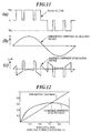
- the compensator terminal output voltage Since the compensator terminal output voltage has been generated on the basis of the modulation signal, the fundamental component of the output voltage looks the same as the modulation signal, as shown in Fig. 11b. However, the compensator terminal output voltage also contains harmonics, as shown in Fig. 11c. These harmonics are undesirable because actually the feeding of the voltage from the compensator terminals should only contain the fundamental component as shown in Fig. llb.
- the amount of harmonic component generation will of course depend on the modulation signal amplitude. For example when the amplitude of the modulation signal increases, there finally exists a case where the amplitude of the modulation signal exceeds the amplitude of the respective carrier signal all times such that the application of the capacitor voltage to the terminals 3a, 3b will be a square wave entirely corresponding to the shape of the fundamental component. That is, when the modulation index equals 1 then of course the content of the fundamental component will be larger than any harmonics components.
- Fig. 12 shows the fundamental amplitude and effective value (root mean square) of harmonics and it can be seen that the harmonics component varies in accordance with the modulation signal (fundamental component), i.e. more precisely with respect to the modulation index.
- the higher harmonics have a lower value than the fundamental component such that in a region between 0.65-1 (for the example investigated in Fig. 12) a modulation index control of the compensator output voltage can be used, i.e the amplitude of the modulation signal should be varied in accordance with the output voltage desired to be produced.
- the harmonics effective value is larger than the fundamental component in a low modulation index region (low fundamental component region) of ⁇ 0.65. Therefore, it would be preferable to select a constant modulation index control with a high modulation index of ⁇ 0.65 since then a sufficient harmonic suppression can be achieved.
- the constant modulation index control has other problems such as that the controllability of the DC voltage is degraded in zero or very low DC voltage region since the active voltage cannot be injected sufficiently into the line. Therefore, the constant modulation index control is not applicable for all values of the compensator terminal output voltage.
- a current controller 20 adjusts the DC voltage.
- the compensator terminal output voltage is zero, then also the DC control voltage is zero. In such a case it is not possible any longer to draw active power from the transmission line to the DC capacitor and the DC voltage cannot be controlled any more.
- the DC capacitor C DC must be charged by a battery or a pre-charge circuit.
- the United States Patent US 5,198,746 uses an absolute value circuit which clamps the voltage to a predetermined value even at the zero output terminal voltage of the inverter. Thus, controllability is maintained.
- the DC capacitor voltage goes to zero at a low compensator output terminal voltage if the DC voltage has perturbations in a single phase inverter.
- controllability of the output terminal voltage is reduced.
- the reason for these perturbations is that the DC current of a single phase inverter comprises second harmonic perturbations due to instantaneous power variations. Consequently, in the absence of a second harmonic filter in the DC circuit, also the DC voltage has a perturbation of the same frequency. If the amplitude of the DC voltage perturbation is larger than the mean value of the DC capacitor voltage, the instantaneous DC capacitor voltage goes to zero. Due to the use of anti-parallel diodes the inverter cannot provide a negative DC voltage and therefore the compensator terminal output voltage is not controllable when perturbations cause the DC capacitor voltage to drop below zero.
- the compensator terminal output voltage u c cannot only be controlled by the modulation index (i.e. the amplitude of the modulation signal) but also by changing the DC capaciter voltage u DC instead of the modulation index. The reason is that the compensator terminal output voltage u c depends on the magnitude of the capacitor voltage u DC .
- the compensator terminal output voltage u c can be controlled by the capacitor DC voltage and/or the amplitude of the modulation signal.
- the line current i can be controlled (increased/decreased) by the voltage (by the amplitude and the phase of the compensator terminal output voltage u c ) output by the compensator 3.
- Fig. 13 and Fig. 14 show examples of output voltage waveforms respectively for the constant DC voltage method and the adjustable DC voltage method.
- Fig. 15 shows the effects of the adjustable DC voltage control method.
- Fig. 15 shows the fundamental component and the harmonics component of the adjustable DC voltage with unitary modulation index. Since the waveform is similar to that of the unity modulation index in the whole region, the ratio of the fundamental wave and the harmonics component is the same for all modulation indices. Consequently, the harmonics component is always lower than a fundamental component and is less than that of the constant DC voltage control (i.e. variable modulation index control as shown with the dashed lines in Fig. 12 and 15).
- the harmonics of the line current entirely depend on the harmonics of the output voltage of the inverter. If the adjustable DC voltage method (i.e. constant modulation index) is used, the content of the harmonics will always be lower than the content of the fundamental component such that no problem arises.
- the adjustable DC voltage method i.e. constant modulation index
- the current in the inverter components is the same since this current is actually a line current i flowing through the line.
- the losses of the inverter components such as the tyristors and diodes intrinsically depend on the flowing current. If the switching frequency is reduced, the device losses are also reduced. However, if the switching frequency is reduced, the harmonics in the compensator terminal output voltage u c will be increased. Thus, the switching frequency cannot be reduced under a predetermined limit set by the maximum harmonics generation. Thus, during low loss operation of the inverter (lower switching frequency the value of which is limited to a lower limit) only the reducing of DC capacitor voltage can further reduce harmonics (if a constant temperature condition is assumed). In addition, the reduction of the DC capacitor voltage also reduces a leakage loss in a DC capacitance or components of the filters in the compensator.
- the current amplitude of the current i is mainly proportional to voltage u L over the inductance of the simplified transmission line 2a, 2b.
- the compensator 3 can change the voltage u L by injecting a compensation voltage u c at the compensator terminal output voltage.
- the change of the current amplitude is therefore proportional to the amplitude of injected voltage u c .
- the output of the current controller should have a linear relationship with the injection voltage u c . If the controller's output of the current control is proportional to the compensation voltage u c , the controller can operate linearily.
- the current controller can simply change its output mq (cc out ) to twice the value it had before. That is, the current amplitude is proportional to the (overhead voltage u x ) - (injected voltage u c ).
- the DC voltage at the capacitor may go to zero on this transient state.
- zero voltages must be avoided since the switching elements of the inverter can only handle positive voltages. Therefore, during a transient decrease of the reference voltage when using an adjustable DC voltage control of the line current, there is the additional problem of zero voltages at the capacitor.
- Fig. 16 shows the same dependency as indicated with the schematic lines in VDEP, CDEP in Fig. 10.
- Fig. 17b shows examples of the frequency characteristics of the transfer functions of Fig. 16 and different current amplitudes of the power transmission lines.
- the coupling from the active component of the modulation index m d to the current amplitude i d is larger than the main transfer function of the current amplitude.
- the other coupling has a larger gain at high frequency region compared to the main transfer function.
- the main transfer functions are varied by the operation point (in this case current amplitude), thus the control performance will be degraded using a control system as in Fig. 16.
- the coupling control of Fig. 10, 16 takes place independently as to whether a single-phase system or a three-phase system is considered.
- Fig. 17a shows the step responses of the basic control including the coupling control.
- the DC voltage is changed in a step function (in order to determine the dynamic coupling of the voltage to the current) there is a large pulse in the AC line current.
- a step function - similar change of the DC line current e d is performed, then - at time point 0.5 - a variation of the DC voltage also occurs. Therefore, also Fig. 17a illustrates that the voltage and current control cannot be performed independently in the conventional controllers for the transformerless reactive series compensator.
- the conventional controllers either operate with a variable modulation index and constant DC voltage or with a constant modulation index and variable DC voltage.
- the problem of harmonic generation in the compensator terminal output voltage still remains.
- the problem of the DC voltage dropping to zero which makes control impossible.
- there is the problem of switching losses and leakage losses of the capacitor There is also the problem of zero voltage in transient behaviours.
- the present invention has been devised to overcome the aforementioned problems.
- the main object of the present invention is to provide a controller which reduces the generation of harmonics in the compensator terminal output voltage and nonetheless avoids zero voltages.
- the control is performed on such a manner that the adjustable DC voltage control is used for a high output voltage region and the constant DC voltage control is used for the low output voltage region.
- the harmonics are reduced and in the low output voltage region the harmonics are still reduced compared to a constant high DC voltage control.
- Such a controller also avoids zero DC voltages at the DC capacitor and maintains a minimum DC voltage also for the continuous operation from capacitive to inductive mode or vice versa.
- the controller according to the invention also has the advantage of reducing the switching losses since at least at the adjustable DC voltage control a constant modulation index can be selected such that the switching frequency is as small as possible.
- the controller comprises a rate limiter for restricting the change rate of the predetermined voltage applied to the voltage control loop. This avoids steep drops of the capacitor DC voltage to zero in transient. Therefore, the rate limiter in the adjustable DC voltage region in particular solves the object of avoiding zero DC voltages in transient conditions, especially at a sudden change of the current reference.
- the controller further comprises decoupling control means receiving a modulation index m q ' from the current controller and a modulation index m d ' of the DC voltage controller and outputting new modulation indices m q and m d to the modulation signal generation means such that the line current is independent from the output md' of the DC voltage controller and the DC capacitor voltage is independent from the output mq' of the current controller, wherein the AC current amplitude and the DC capacitor voltage can be controlled independently.
- the decoupling control means is provided within the voltage and current control loops and is adapted to make the current control independent of the modulation index of the voltage control and to make the voltage control independent of the current modulation index. In combination with the rate limiter, this improves further the dynamic behaviour of the controller during sudden changes of the reference voltage in transient conditions.
- a first control method is a technique where the amplitude of the modulation signal m is changed which leads to a variation of the pulsewidth and thus to a variation of the output voltage u c (see Fig. 13).
- a second control method is a technique in which the output voltage u c is changed by changing the DC capacitor voltage u DC . Both methods have their problems regarding the generation of harmonics, the falling below zero of the DC capacitor voltage (preventing control and the taking of active power from the line) and switching losses.
- a controller according to the first aspect of the invention for avoiding these problems will be described with reference to Fig. 18a, Fig. 18b and Fig. 19.
- the current controller 20 outputs a control signal corresponding to the desired compensator terminal output voltage u c of the compensator. Furthermore, dependent on a predetermined reference voltage u DC ref the voltage controller 16 outputs the modulation index m d for said modulation signal.
- the coupling of the control method selection means SS to the voltage control loop allows to adjust the predetermined reference voltage u DC ref dependent on the current controller output cc out which indicates the desired compensator terminal output voltage.
- a combined control of the compensator terminal output voltage u c is possible by adjusting the modulation index mq (changing the amplitude of the modulation signal) and/or the reference voltage u DC ref (adjusting the amplitude of the DC capacitor voltage u DC ).
- Fig. 19 shows the function of the control method selection means SS. Since the output voltage can be controlled by both the DC voltage u DC as well as the modulation index m q , the selection means SS provides that the adjustable DC voltage control is used for a high output voltage region and the constant DC voltage control is used for a low output voltage region. The high voltage and low voltage region are separated by a predetermined compensator terminal output voltage threshold u cth , e.g. 20% of the maximum DC voltage.
- the control method selection means SS When the compensator terminal output voltage u c is smaller than said predetermined compensator terminal output voltage threshold u cth , i.e. u c ⁇ u cth , then the control method selection means SS outputs a substantially constant reference voltage u DC ref and a modulation index m q increasing and decreasing a depending on an increase or decrease of the compensator terminal output voltage u c as indicated by said current controller output cc out .
- the harmonics content In the low output voltage region u c ⁇ u cth the harmonics content is not as reduced as shown in Fig. 15, however, it is still reduced compared to the constant high DC voltage method indicated with the dashed line in Fig. 19.
- the constant DC capacitor voltage used in the lower terminal output region is set to such a value that even a maximum perturbation cannot cause a zero voltage, then a minimum DC voltage is maintained and thus the controllability of the output terminal voltage is ensured for the whole operating range.
- a constant modulation index is used which is set to a maximum modulation index m q max .
- this maximum modulation m q max must be an index which allows to reduce the effective value of the harmonics component to be smaller than the effective value of the fundamental component, and therefore, at such a modulation index m q max the harmonics component is always smaller than the fundamental component in the constant modulation index range.
- the main control loops of line current control and DC voltage control are interconnected via the signal separator SS which receives the output of the current controller cc out and which outputs the modulation m q and the DC voltage reference u DC ref .
- the line current is controlled by adjusting the output voltage and the control output signal cc out of the current controller 20 is separated to the DC voltage reference and the modulation index by the signal separator SS.
- the line current i is controlled not only by the modulation index but also by the DC voltage.
- control method selection means (signal separator SS) must ensure the minimum DC capacitor voltage by some limiting means and must adjust the modulation index to control the output voltage at the minimum DC voltage. In the higher output voltage region the current is controlled by DC voltage only and in the lower output voltage region it is controlled by the modulation index with the minimum constant DC voltage.
- Fig. 20 shows a first embodiment of a signal separator SS1.
- the control signal cc out of the current controller 20 which is input to the signal separator SS1 is the amplitude of the compensator terminal output voltage u c . Since the maximum output voltage u c of the compensator is basically the maximum DC capacitor voltage, also the output of the current controller cc out has a maximum value determined by the maximum DC capacitor voltage.
- a first limiter 200 is provided for limiting the control voltage cc out to a voltage level u DC min when the control voltage cc out exceeds this predetermined limit voltage u DC min . Likewise, if the control voltage cc out falls below the negative limit voltage -u DC min then the control voltage cc out will be limited to this negative limit voltage u DC min . Furthermore, a first divider 201 is provided for multiplying the output of the first limiter 200 with the maximum modulation index m q max and for dividing the result by the first limit voltage u DC min . The output of the first divider 201 is the modulation index mq. Thus, in the upper signal part 200, 201 in Fig.
- a variable modification index mq increasing and decreasing (e.g. linearily) with an increase or decrease of the control voltage cc out is output.
- the limit voltage u DC min corresponds to the threshold voltage u cth as explained with reference to Fig. 19.
- a first absolute value circuit 202 is provided for determining the absolute value of the control voltage cc out .
- a second limiter 203 is provided for setting the reference voltage u DC ref to a minimum voltage U DC min if the output of the absolute value circuit 202 falls below this lower voltage value u DC min .
- the second limiter 203 is also adapted for limiting the output of the absolute value circuit 202 to an upper threshold value u DC max .
- the limiter 203 in the lower path outputs the minimum DC voltage which thus corresponds to the constant DC voltage control method, i.e. a variable modulation index depending on the gain of the limiter 200 is output whilst a constant DC voltage is set via the constant reference voltage u DC ref .
- a control voltage cc out exceeding the minimum voltage u DC min the control voltage cc out multiplied with the gain of the second limiter 203 is output as the reference voltage u DC ref .
- the adjustment of the gain of the limiters 200, 203 is preferably adapted to the control behaviour of the current control loop and the voltage control loop (PI, PID etc.).
- m q max is preferably selected to be +1. However, other values are possible. If m q max ⁇ 1 the modulation index for the current control is limited less than 1 and the inverter can additionally output voltage for the DC voltage control. That is, the maximum output voltage is limited by the DC capacitor voltage and the output voltage is maximum at the modulation index being one in the PPM method as shown in Fig. 11. If the current controller 20 outputs the maximum modulation index and the DC capacitor voltage requires to take power from the transmission line, a sinusoidal modulation signal m in Fig. 11 will exceed 1 and as a result the output voltage will be distortet.
- the modulation index m q max is selected to be less than one, a control margin to control the DC voltage is possible.
- the modulation index maximum value must be selected to be a value which ensures that the effective value of the harmonics component is smaller than the effective value of the fundamental component (see Fig. 12 and Fig. 19).
- FIG. 21 A second embodiment of a signal separator SS2 having the control characteristics as shown in Fig. 22a is shown in Fig. 21.
- This signal separator SS2 comprises a third limiter 211 for limiting the control voltage cc out output by the current controller to a maximum modulation index m q max and a minimum modulation index m q min when the control voltage cc out respectively exceeds or falls below the maximum and minimum modulation indices, respectively.
- cc out is the modulation index level.
- the maximum modulation index m q min may be the negative value of m q max .
- the signal separator SS2 comprises a second absolute value circuit 213 for determining the absolute value of the control voltage cc out .
- a first multiplier 212 multiplies the output of the absolute value circuit with a predetermined constant K 2 .
- a fourth limiter 214 limits the output of the second multiplier 212 to an upper threshold value u DC max and a lower threshold voltage u DC min when the output of the second multiplier 212 respectively exceeds said upper and lower threshold voltages u DC max , u DC min .
- the first multiplier 212 uses a predetermined constant K 2 for converting the control voltage cc out into the DC voltage reference level.
- the predetermined constant K 2 can also be incorporated as part of a gain of the fourth limiter 214.
- the constant K 2 is part of the absolute value circuit 213 which in this case comprises a gain factor corresponding to the constant K 2 .
- the signal separators SS1, SS2 enable a control with the constant DC capacitor voltage and a variable modulation index in a low voltage output region and with a constant modulation index and variable DC capacitor voltage in the higher output voltage region thus avoiding harmonics in the output voltage at the terminals 3a, 3b. At least in the higher output voltage region a selection of a modulation index will also allow to reduce switching losses. In any case zero DC capacitor voltage is avoided thus allowing the taking of active power from the transmission system into the DC capacitor.
- the current controller output cc out designates the desired terminal voltage at the compensator and the DC voltage controller will maintain the DC capacitor voltage such that the control voltage cc out equals the compensator terminal output voltage u c in the adjustable DC voltage region.
- a steep change in the reference voltage u DC ref could cause an undershoot of the DC capacitor voltage and a zero DC capacitor voltage could occur as a result of the undershoot.
- a change of the control voltage cc out (horizontal axis) and hence a change of the reference voltage u DC ref from A ⁇ B may cause (depending on the dynamic behaviour of the voltage control loop) - an undershoot such that the DC capacitor voltage u DC may become zero.
- the undershoot is a result of the steep and fast decrease of the controller voltage cc out .
- the current amplitude is mainly proportional to the voltage u 1 over the inductance of the simplified transmission line.
- the compensator can change the voltage u l by injecting a compensating voltage u c .
- the change of the current amplitude cc out is therefore proportional to the amplitude of the injected voltage.
- the output voltage cc out of the current controller is desired to have a linear relationship with the injection voltage u c . If the output of the current controller is proportional to the compensation voltage, the controller can operate linearily.
- the current controller should simply change its output cc out to twice the previous value since the current amplitude is proportional to ((overhead voltage u x )-(injected voltage u c )).
- the modulation index mq still keeps constant and the u DC voltage does not follow the desired output signal cc out if the rate limiter is placed before the signal separator.
- the q-axis modulation index mq would start changing earlier and would not be kept constant between t 0 to t 1 '.
- the rate limiter is effective for a safe operation in constant mq operation, but degrades the transient performance.
- the placing of the rate limiter only at the voltage reference u DC ref that is, breaking characteristics of Fig. 22(a) in the transient condition, helps recovery of the transient performance.
- the third limiter is actually the circuit that restricts the change rate of the input signal.
- a third multiplier 252 multiplies the output of the third limiter 255 by the predetermined sampling time T s .
- a second adder 253 having an input receiving the output of the third multiplier 252, a second input and an output constituting the output of the rate limiter is provided.
- the unit 254 is (in discrete sampling time) a unit-sample delay unit for shifting the output of the rate limiter to one sampling time.
- the output of the z -1 circuit 254 is applied to the second input of the first adder 266 and a second input of the second adder 253. If the input is a time discrete signal as shown in Fig. 25b, the output will be the discrete time signal also shown in Fig. 25b.
- the multiplication constant K2 is determined by the ratio of the lower threshold voltage u DC min divided by the maximum modulation index m q max as used in the limiter 261 in the upper signal path.
- the rate limiter restricts the rate of the reference voltage to avoid a steep drop of the DC voltage to zero in transient conditions, especially at a sudden change of the current reference.
- the negative rate is selected slower than the positive rate. That is, the rate limitation for the positive rate change is larger - in absolute value - than the rate change allowed for changes in the negative direction.
- the control trajectory first moves into a horizontal direction from A' to C as shown in Fig. 24b. Then the control trajectory moves down to the steady state point B'.
- the desired control trajectory in the constant DC voltage control region is a direct path from A' to B'.
- the fact that an operation is out of the desired control trajectory can also happen without the rate limiter when the DC voltage does not follow its reference due to a slow response behaviour.
- the provision of the rate limiter enhances this problem.
- the result of the introduction of the rate limiter is that the injection voltage u c is not proportional to the control voltage cc out - even in the control region where only the variable DC capacitor control is used.
- the dashed line indicates the ideal response which is still proportional to the control voltage cc out despite the provision of the rate limiter.
- the signal separator SS can be used in connection with such a decoupling control means 25.
- the signal separator SS may or may not contain the rate limiter.
- the rate limiter is used this further deteriorates the response behaviour of the control loops and the use of the decoupling control will be particularly advantageous.
- Fig. 27b shows the third aspect of principle block diagram of a controller according to the invention.
- the inventive controller comprises a current detector 24 and a current control loop formed by the feedback path 21, 18 and the forward path including the current controller 20.
- a voltage control loop comprises the voltage detector 26, the feedback path 15 and a forward path comprising the DC voltage controller 16.
- the inventive controller comprises a decoupling control means 25 downstream of the current controller 20 and the DC voltage controller 16.
- the decoupling control means 25 outputs a first modulation control signal m q for controlling the line AC current i and a second modulation control signal m d for controlling the compensator output voltage.
- the first and second control signals m q , m d are selected such that a change in the first control signal mq will not influence the DC control voltage u DC , i.e. such that the capacitor voltage u DC is independent of the control signal m u output by the current controller 20.
- the second control signal m d is selected such that it does not influence the line current, i.e. the line current i is independent from the second control signal m d .
- the decoupling control means 25 must perform some kind of inverse operation such that the coupling effects due to the current transfer function block CTF, the voltage transfer function block VTF, the voltage current transfer block VCTF and the current voltage transfer function block CVTF are canceled. That is, if the current controller 20 and the voltage controller 16 operate as in the conventional system in Fig. 10, then the decoupling control means 25 will output some kind of predestorted modulation indices m q' , m d' which - when transferred through the blocks CTF, VCTF, CVTF, VTF will precisely cancel the effects of these blocks. In particular, the decoupling control means 25 allows to get rid of the cross-coupling blocks VCTF, CVTF which cause the coupling of the current control loop and the voltage control loop.
- equation (4.9) can be considered as a non-linear differential equation of m d it is not possible to realize this equation in an on-line controller because the coefficient of the derivative is i q which takes positive or negative values around zero.
- the time derivative of m d in equation (4.9) can be ignored such that the modulation m d can be calculated as follows:
- equation (4.11) and (4.10) a perfect decoupling control can not be realized since these equations still depend on the circuit parameters such as resistance, inductance and capacitance.
- equation (4.10) the main coupling is still the time derivative of m d . .
- Fig. 28 shows the controller according to Fig. 9 (i.e. including an AC voltage detector 23, a voltage PLL phase detector 18 and the phase rotation means 17) but also including - according to the fifth embodiment of the invention - a decoupling control means 25.
- the decoupling control means 25 receives the output (modulation index) mq' of the current controller 20, the DC capacitor voltage u DC , the current amplitude i d , the line frequency ⁇ and the output m d ' of the DC voltage controller 16.
- the decoupling control means 25 receives the output (modulation index) mq' of the current controller 20, the DC capacitor voltage u DC , the current amplitude i d , the line frequency ⁇ and the output m d ' of the DC voltage controller 16.
- the decoupling control means 25 the compensator 3, the 2f-filter 15 and the DC voltage controller 16 is provided three times.
- the current detector 24 i.e. the current detector 24, the current amplitude and phase detection units 21, 18, the capacitor voltage detector 26, the mean voltage detector 15, the reference phase generation unit 17 (keeping i q in the control system 0), the reference frame detection 18, the coordinate transformation 19, the DC ripple compensation unit 13 and the voltage phase detector 23 correspond to those units already described in Fig. 9.
- the resulting AC current and output voltage of the compensator without the DC voltage fluctuation means 13 and the 2f filter 15 include some harmonics, however, the decoupling control is effective even without these units. These units can preferably used in certain applications to suppress the harmonics. For example, if the capacitance of the DC capacitor is large enough to suppress the fluctuation then no additional units are needed. Alternatively, if the 2f filter (e.g. an LC filter) is configured with the DC capacitor in parallel in the DC circuit of the compensator 3, the units 13, 15 are again not needed. The latter solution is practically a realistic solution for the transformerless series compensator.
- the 2f filter e.g. an LC filter
- the output m d ' is multiplied with the constant K d in the multiplier 25j.
- K d the constant K d in the multiplier 25j.
- the equations (4.16), (4.17) can be rescaled such that K d is 1 such that the additional multiplier 25j is not necessarily needed, i.e. K d can be unity.
- the output mq' of the current controller is multiplied with the constant Kq in the multiplier 25k (Kq can also be unity due to a normalization).
- the multiplied signal N1 forms the nominator of the first divider 25a.
- the detected DC voltage u DC is multiplied by the reference frame frequency ⁇ in the multiplier 25b.
- the multiplied signal D 1 is the denominator used for the division in the divider 25a.
- the output DV1 of the first inverter is supplied to an adder 25i.
- the line frequency ⁇ is the denominator for the division in the second divider 25c and a signal N2 output from the filter is the nominator of the second divider 25c.
- the multiplied signal DV2 is applied as inverted input to the adder 25i.
- the main loop of the capacitance voltage control is designed to a limited band width in its frequency characteristics, placing a filter 25f with a small time constant in the main loop does not affect the characteristics of the main loop.
- the integrator 25h, the gain 25g and the subtractor 25f act together as filter and the input of the filter is the pure differentiation of m d with respect to time. Therefore, this coupling can perform a compensation properly by a pure differentiation using the filter function.
- the coupling of the other side which is compensated by division of the current is also filtered.
- response of the current is also limited because of the inductance of the transmission lines and responses of the feedback control of the current amplitude.
- the filter 25f, 25g, 25h having a small time constant T f in the main loop does not affect the characteristics of the main loop.
- the integrator 25h, the gain 25g and the subtractor 25f act together as the filter and the input N 2 of the integrator 25h is the pure differentiation of Md with respect to time.
- the input of the integrator 25h forms the nominator M 2 of the divider 25c.
- Fig. 31a shows by contrast to Fig. 17a of the prior art the step responses using a decoupling control. Whilst at time point 0.1 in Fig. 17a the current amplitude i d shows a ripple due to coupling, there is no change whatsoever if a voltage step occurs in Fig. 31a at time point 0.1. Likewise, if the current has a step at time point 0.5 in Fig. 31a, there is no variation of the voltage at all. Thus, Fig. 31a shows that the current end voltage can be controlled independently on the basis of the equations (4.16), (4.17).
- Fig. 28 together with Fig. 29 shows an embodiment of the invention comprising a three-phase system using a voltage PLL and an independent and local control
- the controller does not need a AC voltage detector 26 shown in Fig. 28.
- the configuration of the sixth embodiment is therefore constructed like Fig. 28 and omitting the voltage detector 23 and the phase rotation means 17 and connecting the output of the current detector 24 also to the phase detector 18 which now acts as a current PLL unit 18.
- the three-phase polar transformation unit 21 is the same as in Fig. 28 and the phase detector 18 directly outputs the sin ⁇ and cos ⁇ functions.
- the fifth embodiment the fifth embodiment.
- Fig. 30a shows a single phase system having the basic construction of Fig. 8 and having a decoupling control means 25 and a component detector 26 according to a seventh embodiment of the invention.
- the current detection is also phase. Since the current detection is single phase, it is not possible to provide the q-axis component of the current iq to be zero by a reference frame detection. Therefore, in Fig. 30a the equations shown in Fig. 27c, namely equations (4.14), (4.15) are realized.
- a single phase to d-q coordinate transformation of the current is needed (see Fig. 30b) in order to provide the i d and i q components needed in the decoupling control means 25 as shown in Fig. 30a.
- the decoupling control means 25 comprises, in addition to the units 25a-25k an additional multiplier 251 and an additional adder 25m.
- the multiplier 251 multiplies the q-axis current component iq with the output of the first divider 25a and feeds a multiplied output ML to the negative input of the adder 25m.
- the adder 25m subtracts i q *DV 1 (i.e. i q *m q 'K q /u DC ⁇ from m d 'K d ).
- the output of the adder 25b forms the nominator signal M 3 of the third divider 25d. With such a configuration the full equations (4.14), (4.15) can be realized.
- Fig. 30b The AC line current i detected by the current detector 24 is multiplied by the sinusoidal reference signals cos( ⁇ t) and sin( ⁇ t) which are produced by the phase detector 18.
- the component detector 26 comprises a first and second multiplier 26a, 26b for multiplying the detected line current i with the signals sin( ⁇ t) and cos( ⁇ t) to produce the orthogonal current components i d , i q .
- the reference signal cos ( ⁇ t) is a signal in-phase to the AC current, and therefore icos ⁇ t and isin ⁇ t include the amplitude of the AC current i d and the transient component i q , respectively.
- the component detector 26 outputs the i d and i q components.
- the 3-phase-polar transformation unit 21, the phase detector 18 and the phase rotation unit 17 correspond to those units already described with reference to Fig. 28. It is interesting to note that the decoupling control of the single-phase system with the voltage PLL version can be simplified just like in the case of the three-phase system with voltage PLL in Fig. 28 and Fig. 29. Because there is employed a phase correction from the voltage phase to the current phase this control makes the decoupling just a simple as in Fig. 29. Of course, by contrast to Fig. 28, there is an additional delay in the control loop because of the component detection in the component detector 26. However, the decoupling control 25 operates with the corrected reference frame in which the q-component of the current is made zero.
- a further filter 27 can be used for filtering the input reference voltage u DC ref .
- Such a filter 27 can also be used in each of the fifth, sixth and seventh and eighth embodiments as illustrated in Fig. 18-32 and explained above.
- the filter has the effect of reducing the amplitude of the modulation index and thus a decoupling control is achieved with a restricted output voltage capacity. Since the high frequency components of the input reference voltage are reduced by the filter, these components are not transferred to the decoupling control units. As a result, the output of the gain unit 25g will be reduced. This means, if the gain of the DC voltage controller is low and/or the input reference voltage is slow, the decoupling control unit DV2 can be neglected.
- a voltage PLL is used because the usage of the voltage PLL is generally known.
- the sixth embodiment has no voltage PLL and its advantage is a reduction of components.
- the seventh embodiment uses no voltage PLL to illustrate simply the application of the invention in a single phase system.
- the single phase system can operate with the voltage PLL and the voltage detector as shown in Fig. 32b according to the eighth embodiment.
- the additional filter according to the nineth embodiment can be used in any of the other embodiments. Of course the embodiments can be combined.
- the 2f filter and the DC voltage fluctuation compensation means are optional units as explained above.
- the signal separator SS in accordance with the first and second aspect of the invention can be used in connection with the decoupling control means. That is, the current controller 20 outputs the control voltage cc out and the signal separator outputs the modulation index mq' whilst the decoupling control means outputs new modified modulation indices mq and m d as explained above.
- Fig. 33a shows a similar block diagram as Fig. 33a, for a single phase system.
- a preferable signal separator to be used in Fig. 33a, 33b is illustrated in accordance with the eleventh embodiment in Fig. 34. It comprises in the lower signal path an absolute value circuit 341 and a limiter 342 and a rate limiter 343 which perform the similar functions as the units 233, 234 and 235 in Fig. 23.
- the modulation index mq' output by the signal separator SS5 is the control voltage cc out .
- the dynamic characteristics are shown in Fig. 35a and Fig. 35b. Whilst the control trajectory goes from point A' to point B' through C, in Fig. 35a and Fig. 35b the control trajectory of the modulation index mq directly moves from A' ' to B' ' due to the decoupling control. As shown in Fig. 35b, this means that the modulation index is not constant in transient and consequently the output terminal voltage (in the lowest diagram in Fig. 35b) is directly proportional to cc out which equals mq'. Therefore, the current response can be improved by the signal separator in Fig. 34 together with the decoupling control.
- a rate limiter is used in the lower signal path, as shown in Fig. 23, Fig. 26 or Fig. 34, possibly combined with a decoupling control.
- the rate limiter is only inserted into the control path for the adjustable DC voltage control.
- any controller which does not even use the first aspect of the invention i.e. a controller which uses the conventional DC adjustable control method over the complete compensator terminal output voltage range will benefit from the use of a rate limiter and possibly of the use of a rate limiter together with a decoupling control. That is, any controller in Fig. 18a which outputs a permanently constant modulation index m q but which outputs a variable DC reference voltage u DC ref may only use the lower signal path elements in Fig. 23, 26 and Fig. 34, possibly in combination with the decoupling control means. This will allow in a controller which only uses the adjustable DC voltage control method to avoid zero voltages when there is a sudden large decrease in the current controller output cc out .
Priority Applications (4)
| Application Number | Priority Date | Filing Date | Title |
|---|---|---|---|
| EP00107015A EP1168564A1 (de) | 2000-03-31 | 2000-03-31 | Regler regelbarer Gleichspannung für einen trasformatorlosen Serienblindleistungskompensator |
| JP2000276214A JP4230648B2 (ja) | 2000-03-31 | 2000-09-12 | 無効電力直列補償器用コントローラ |
| US09/671,156 US6242895B1 (en) | 2000-03-31 | 2000-09-28 | Controller of adjustable DC voltage for a transformerless reactive series compensator |
| CNB001348760A CN1214504C (zh) | 2000-03-31 | 2000-09-30 | 用于无变压器式无功串联补偿器的可调直流电压控制器 |
Applications Claiming Priority (1)
| Application Number | Priority Date | Filing Date | Title |
|---|---|---|---|
| EP00107015A EP1168564A1 (de) | 2000-03-31 | 2000-03-31 | Regler regelbarer Gleichspannung für einen trasformatorlosen Serienblindleistungskompensator |
Publications (1)
| Publication Number | Publication Date |
|---|---|
| EP1168564A1 true EP1168564A1 (de) | 2002-01-02 |
Family
ID=8168340
Family Applications (1)
| Application Number | Title | Priority Date | Filing Date |
|---|---|---|---|
| EP00107015A Withdrawn EP1168564A1 (de) | 2000-03-31 | 2000-03-31 | Regler regelbarer Gleichspannung für einen trasformatorlosen Serienblindleistungskompensator |
Country Status (4)
| Country | Link |
|---|---|
| US (1) | US6242895B1 (de) |
| EP (1) | EP1168564A1 (de) |
| JP (1) | JP4230648B2 (de) |
| CN (1) | CN1214504C (de) |
Cited By (2)
| Publication number | Priority date | Publication date | Assignee | Title |
|---|---|---|---|---|
| CN101404461B (zh) * | 2008-11-13 | 2010-12-08 | 山东大学 | 用于三相三线电压型功率变换器的电流解耦控制方法 |
| CN102222922A (zh) * | 2011-06-10 | 2011-10-19 | 湖南大学 | 采用下垂控制策略的statcom控制系统及其控制方法 |
Families Citing this family (38)
| Publication number | Priority date | Publication date | Assignee | Title |
|---|---|---|---|---|
| EP1249061B1 (de) * | 2000-04-25 | 2004-08-18 | SP Systems Pte Ltd | Dynamischer serienspannungskompesator und dazugehöriges verfahren |
| US6515486B1 (en) * | 2000-06-22 | 2003-02-04 | Xilinx, Inc. | Method and structure to determine low threshold voltage and high threshold voltage |
| EP1195886A1 (de) * | 2000-09-29 | 2002-04-10 | ABB Schweiz AG | Rückwärtsleitender Gate Commutated Thyristor sowie dessen Anwendung |
| SE517777C2 (sv) * | 2000-11-30 | 2002-07-16 | Abb Ab | Anordning och förfarande för spänningsreglering i ett elektriskt transmissionsnät |
| CN1305198C (zh) * | 2003-06-18 | 2007-03-14 | 清华大学 | 基于链式逆变器的无功发生装置的直流电压平衡电路 |
| JP3992679B2 (ja) * | 2003-12-25 | 2007-10-17 | 三菱電機株式会社 | 電力変換装置 |
| JP4304122B2 (ja) * | 2004-05-25 | 2009-07-29 | 三菱電機株式会社 | 電気車制御装置 |
| JP5002812B2 (ja) * | 2006-03-14 | 2012-08-15 | 国立大学法人東京工業大学 | 自励式無効電力補償装置および自励式無効電力補償装置におけるコンデンサ電圧制御方法ならびに電力蓄積装置および電力蓄積装置制御方法 |
| CN101335453B (zh) * | 2007-06-29 | 2012-02-08 | 上海磁浮交通工程技术研究中心 | Statcom的控制方法 |
| CA2753998C (en) * | 2009-03-09 | 2016-05-03 | Abb Technology Ag | Control device, reactive power compensator and method |
| US8174270B2 (en) * | 2009-07-17 | 2012-05-08 | The Invention Science Fund I, Llc | Systems and methods for assessing standoff capabilities of in-service power line insulators |
| US8456168B2 (en) * | 2009-07-17 | 2013-06-04 | The Invention Science Fund I Llc | Systems and methods for testing the standoff capability of an overhead power transmission line |
| US20110011621A1 (en) * | 2009-07-17 | 2011-01-20 | Searete Llc, A Limited Liability Corporation Of The State Of Delaware | Smart link coupled to power line |
| US8692537B2 (en) * | 2009-07-17 | 2014-04-08 | The Invention Science Fund I, Llc | Use pairs of transformers to increase transmission line voltage |
| US8426736B2 (en) * | 2009-07-17 | 2013-04-23 | The Invention Science Fund I Llc | Maintaining insulators in power transmission systems |
| JP5478536B2 (ja) | 2011-02-22 | 2014-04-23 | 株式会社京三製作所 | 三相コンバータの力率制御方法、三相コンバータの無効電力制御方法、三相コンバータの制御装置 |
| CN102646986B (zh) * | 2012-03-22 | 2014-02-12 | 山东电力集团公司济南供电公司 | 磁控电抗器控制器及其方法 |
| GB201206318D0 (en) * | 2012-04-10 | 2012-05-23 | Imp Innovations Ltd | A power compensator |
| JP5580377B2 (ja) * | 2012-08-30 | 2014-08-27 | オリジン電気株式会社 | 静止型無効電力補償装置及び電圧制御方法 |
| US20140376283A1 (en) * | 2013-06-21 | 2014-12-25 | Hamilton Sundstrand Corporation | Systems and methods for active damping device for stabilizing a power grid of active sources and loads |
| JP6372642B2 (ja) * | 2013-09-14 | 2018-08-15 | 株式会社MERSTech | 無効電力制御装置、無効電力制御方法及びプログラム |
| CN103532155B (zh) * | 2013-10-29 | 2016-03-30 | 山东华天电气有限公司 | 集中控制的多模块静止同步补偿器及其控制方法 |
| RU2555187C2 (ru) * | 2013-11-15 | 2015-07-10 | Федеральное государственное унитарное предприятие "Крыловский государственный научный центр" | Устройство контроля работы однофазного инвертора |
| US9458830B2 (en) * | 2014-09-05 | 2016-10-04 | General Electric Company | System and method for improving reactive current response time in a wind turbine |
| US10560036B2 (en) * | 2015-09-17 | 2020-02-11 | Mitsubishi Electric Corporation | Power conversion device for reliable control of circulating current while maintaining voltage of a cell |
| JP6509352B2 (ja) * | 2015-09-17 | 2019-05-08 | 三菱電機株式会社 | 電力変換装置 |
| WO2017046909A1 (ja) * | 2015-09-17 | 2017-03-23 | 三菱電機株式会社 | 電力変換装置 |
| EP3439162B1 (de) * | 2016-03-28 | 2021-11-17 | Mitsubishi Electric Corporation | Stromwandlungsvorrichtung |
| CN106340877A (zh) * | 2016-09-29 | 2017-01-18 | 广东电网有限责任公司电力科学研究院 | 一种有源电力滤波器直流侧电压控制方法及装置 |
| FR3068836B1 (fr) * | 2017-07-07 | 2019-08-23 | Stmicroelectronics (Rousset) Sas | Circuit de protection d'un commutateur de puissance |
| JP6968361B2 (ja) * | 2017-08-18 | 2021-11-17 | 株式会社Gsユアサ インフラシステムズ | 電力変換回路及びその制御法 |
| US10396533B1 (en) * | 2018-02-22 | 2019-08-27 | Smart Wires Inc. | Containerized power flow control systems |
| CN109038677A (zh) * | 2018-09-05 | 2018-12-18 | 淮阴工学院 | 一种高效的六开关单相并网变流器 |
| CN110286278B (zh) * | 2019-06-04 | 2021-12-03 | 广州智光电气技术有限公司 | 一种输出电压控制方法、装置和电网适应性检测平台 |
| US11349310B2 (en) * | 2019-11-15 | 2022-05-31 | Smart Wires Inc. | Adaptive control technique for stability of impedance injection unit |
| US11522451B2 (en) * | 2019-12-13 | 2022-12-06 | Alpha And Omega Semiconductor (Cayman) Ltd. | Inductor binning enhanced current sense |
| US11374503B2 (en) * | 2020-03-13 | 2022-06-28 | Savannah River Nuclear Solutions, Llc | DC compensation for power transformer through neutral DC injection |
| CN112799891B (zh) * | 2021-01-15 | 2023-05-09 | 网易(杭州)网络有限公司 | iOS设备测试方法、装置、系统、存储介质及计算机设备 |
Citations (2)
| Publication number | Priority date | Publication date | Assignee | Title |
|---|---|---|---|---|
| US5513090A (en) * | 1994-11-15 | 1996-04-30 | Electric Power Research Institute, Inc. | Hybrid series active, parallel passive, power line conditioner for harmonic isolation between a supply and a load |
| EP1133043A1 (de) * | 1999-12-15 | 2001-09-12 | Mitsubishi Electric Corporation | Regler zur Durchführung einer Entkopplungsregelung eines Blindleistungsserienkompensators |
Family Cites Families (3)
| Publication number | Priority date | Publication date | Assignee | Title |
|---|---|---|---|---|
| US5198746A (en) | 1991-09-16 | 1993-03-30 | Westinghouse Electric Corp. | Transmission line dynamic impedance compensation system |
| US5754035A (en) | 1997-01-14 | 1998-05-19 | Westinghouse Electric Corporation | Apparatus and method for controlling flow of power in a transmission line including stable reversal of power flow |
| US6075350A (en) * | 1998-04-24 | 2000-06-13 | Lockheed Martin Energy Research Corporation | Power line conditioner using cascade multilevel inverters for voltage regulation, reactive power correction, and harmonic filtering |
-
2000
- 2000-03-31 EP EP00107015A patent/EP1168564A1/de not_active Withdrawn
- 2000-09-12 JP JP2000276214A patent/JP4230648B2/ja not_active Expired - Fee Related
- 2000-09-28 US US09/671,156 patent/US6242895B1/en not_active Expired - Fee Related
- 2000-09-30 CN CNB001348760A patent/CN1214504C/zh not_active Expired - Fee Related
Patent Citations (2)
| Publication number | Priority date | Publication date | Assignee | Title |
|---|---|---|---|---|
| US5513090A (en) * | 1994-11-15 | 1996-04-30 | Electric Power Research Institute, Inc. | Hybrid series active, parallel passive, power line conditioner for harmonic isolation between a supply and a load |
| EP1133043A1 (de) * | 1999-12-15 | 2001-09-12 | Mitsubishi Electric Corporation | Regler zur Durchführung einer Entkopplungsregelung eines Blindleistungsserienkompensators |
Non-Patent Citations (2)
| Title |
|---|
| BEER A.; STEMMLER H.; OKAYAMA H.: "Hybrid Transformerless Reactive Series Compensators", 8TH EUROPEAN CONFERENCE ON POWER ELECTRONICS AND APPLICATIONS, SEPT. 7 - 9, 1999, vol. CONF.8, 7 September 1999 (1999-09-07), LAUSANNE, CH, pages 1 - 10, XP002137287 * |
| OKOYAMA, H., FUJII, T.: "Large capacity High Performance 3-Level GTO Inverter System for steel Main Rolling Mill Drives", INDUSTRY APPLICATIONS CONFERENCE,THIRTY-FIRST IAS ANNUAL MEETING,CONFERENCE RECORD OF THE 1996 IEEE, vol. 1, 1996, pages 174 - 179, XP002143961 * |
Cited By (3)
| Publication number | Priority date | Publication date | Assignee | Title |
|---|---|---|---|---|
| CN101404461B (zh) * | 2008-11-13 | 2010-12-08 | 山东大学 | 用于三相三线电压型功率变换器的电流解耦控制方法 |
| CN102222922A (zh) * | 2011-06-10 | 2011-10-19 | 湖南大学 | 采用下垂控制策略的statcom控制系统及其控制方法 |
| CN102222922B (zh) * | 2011-06-10 | 2013-01-23 | 湖南大学 | 采用下垂控制策略的statcom控制系统及其控制方法 |
Also Published As
| Publication number | Publication date |
|---|---|
| JP2001286061A (ja) | 2001-10-12 |
| CN1315768A (zh) | 2001-10-03 |
| CN1214504C (zh) | 2005-08-10 |
| US6242895B1 (en) | 2001-06-05 |
| JP4230648B2 (ja) | 2009-02-25 |
Similar Documents
| Publication | Publication Date | Title |
|---|---|---|
| EP1168564A1 (de) | Regler regelbarer Gleichspannung für einen trasformatorlosen Serienblindleistungskompensator | |
| EP1133043B1 (de) | Regler zur Durchführung einer Entkopplungsregelung eines Blindleistungsserienkompensators | |
| Norouzi et al. | Two control schemes to enhance the dynamic performance of the STATCOM and SSSC | |
| EP2424102B1 (de) | Gleichstrom/Wechselstrom-Wandler vom Einzelphasenspannungstyp, Gleichstrom/Wechselstrom-Wandler vom Dreiphasenspannungstyp und Stabilisierungssteuerungsverfahren | |
| US5351181A (en) | Low cost active power line conditioner | |
| US5077517A (en) | Voltage fluctuation and higher harmonics suppressor | |
| Baimel | Implementation of DQ0 control methods in high power electronics devices for renewable energy sources, energy storage and FACTS | |
| US6876178B2 (en) | Hybrid reactive power compensation device | |
| US20040090212A1 (en) | Hybrid reactive power compensation device | |
| Yang et al. | A novel strategy for improving power quality of islanded hybrid AC/DC microgrid using parallel-operated interlinking converters | |
| Ren et al. | Multi-mode control for three-phase bidirectional AC/DC converter in hybrid microgrid under unbalanced AC voltage conditions | |
| Paul | Shunt active and series active filters-based power quality conditioner for matrix converter | |
| Luo et al. | Selective harmonic active tuning control method for hybrid active power filters | |
| US8330433B2 (en) | Control device reactive power compensator and method | |
| EP2833538A1 (de) | Zwischenkreiskondensatorspannungssymmetrierung für geklemmte Mehrpunktumrichtersysteme mit aktiver Einspeisung durch Blindleistung | |
| Salo et al. | A current-source active power filter with a control delay compensation | |
| Wang et al. | Series compensation method to mitigate harmonics and voltage sags and swells | |
| Afsher et al. | DC-Link Voltage Balancing and Regulation of Split-Capacitor VSI Based DSTATCOM | |
| JPH0744841B2 (ja) | 電力変換器の制御回路 | |
| RU2027278C1 (ru) | Трехфазный компенсатор реактивной мощности | |
| Melin et al. | Concepts of a Control Strategy for Multilevel CSC STATCOM toward Reduce its Losses using a Fixed Modulation Index | |
| Yadav | Stability Enhancement for Transmission Lines using Static Synchronous Series Compensator | |
| Al Aman et al. | An Effective Filter Design for Single-Phase Inverters | |
| Gonzatti et al. | PLL-less control for hybrid active impedance | |
| SUNANDA | Analysis of an Auxiliary Fuzzy Logic Based Static Synchronous Series Compensator |
Legal Events
| Date | Code | Title | Description |
|---|---|---|---|
| PUAI | Public reference made under article 153(3) epc to a published international application that has entered the european phase |
Free format text: ORIGINAL CODE: 0009012 |
|
| 17P | Request for examination filed |
Effective date: 20000915 |
|
| AK | Designated contracting states |
Kind code of ref document: A1 Designated state(s): CH DE FR LI Kind code of ref document: A1 Designated state(s): AT BE CH CY DE DK ES FI FR GB GR IE IT LI LU MC NL PT SE |
|
| AX | Request for extension of the european patent |
Free format text: AL;LT;LV;MK;RO;SI |
|
| AKX | Designation fees paid |
Free format text: CH DE FR LI |
|
| 17Q | First examination report despatched |
Effective date: 20080730 |
|
| GRAP | Despatch of communication of intention to grant a patent |
Free format text: ORIGINAL CODE: EPIDOSNIGR1 |
|
| RIC1 | Information provided on ipc code assigned before grant |
Ipc: G05F 1/70 20060101ALI20140327BHEP Ipc: H02J 3/18 20060101AFI20140327BHEP |
|
| RIN1 | Information on inventor provided before grant (corrected) |
Inventor name: FUJII, TOSHIYUKI Inventor name: BEER, ANDREAS |
|
| RAP1 | Party data changed (applicant data changed or rights of an application transferred) |
Owner name: MITSUBISHI ELECTRIC CORPORATION |
|
| INTG | Intention to grant announced |
Effective date: 20140430 |
|
| STAA | Information on the status of an ep patent application or granted ep patent |
Free format text: STATUS: THE APPLICATION IS DEEMED TO BE WITHDRAWN |
|
| 18D | Application deemed to be withdrawn |
Effective date: 20140902 |