EP1168564A1 - Controller of adjustable DC voltage for a transformerless reactive series compensator - Google Patents
Controller of adjustable DC voltage for a transformerless reactive series compensator Download PDFInfo
- Publication number
- EP1168564A1 EP1168564A1 EP00107015A EP00107015A EP1168564A1 EP 1168564 A1 EP1168564 A1 EP 1168564A1 EP 00107015 A EP00107015 A EP 00107015A EP 00107015 A EP00107015 A EP 00107015A EP 1168564 A1 EP1168564 A1 EP 1168564A1
- Authority
- EP
- European Patent Office
- Prior art keywords
- voltage
- output
- current
- controller
- control
- Prior art date
- Legal status (The legal status is an assumption and is not a legal conclusion. Google has not performed a legal analysis and makes no representation as to the accuracy of the status listed.)
- Withdrawn
Links
Images


Classifications
-
- G—PHYSICS
- G05—CONTROLLING; REGULATING
- G05F—SYSTEMS FOR REGULATING ELECTRIC OR MAGNETIC VARIABLES
- G05F1/00—Automatic systems in which deviations of an electric quantity from one or more predetermined values are detected at the output of the system and fed back to a device within the system to restore the detected quantity to its predetermined value or values, i.e. retroactive systems
- G05F1/70—Regulating power factor; Regulating reactive current or power
-
- H—ELECTRICITY
- H02—GENERATION; CONVERSION OR DISTRIBUTION OF ELECTRIC POWER
- H02J—CIRCUIT ARRANGEMENTS OR SYSTEMS FOR SUPPLYING OR DISTRIBUTING ELECTRIC POWER; SYSTEMS FOR STORING ELECTRIC ENERGY
- H02J3/00—Circuit arrangements for ac mains or ac distribution networks
- H02J3/18—Arrangements for adjusting, eliminating or compensating reactive power in networks
- H02J3/1807—Arrangements for adjusting, eliminating or compensating reactive power in networks using series compensators
-
- Y—GENERAL TAGGING OF NEW TECHNOLOGICAL DEVELOPMENTS; GENERAL TAGGING OF CROSS-SECTIONAL TECHNOLOGIES SPANNING OVER SEVERAL SECTIONS OF THE IPC; TECHNICAL SUBJECTS COVERED BY FORMER USPC CROSS-REFERENCE ART COLLECTIONS [XRACs] AND DIGESTS
- Y02—TECHNOLOGIES OR APPLICATIONS FOR MITIGATION OR ADAPTATION AGAINST CLIMATE CHANGE
- Y02E—REDUCTION OF GREENHOUSE GAS [GHG] EMISSIONS, RELATED TO ENERGY GENERATION, TRANSMISSION OR DISTRIBUTION
- Y02E40/00—Technologies for an efficient electrical power generation, transmission or distribution
- Y02E40/30—Reactive power compensation
Definitions
- the invention relates to a controller for controlling a reactive series compensator serially inserted at compensator terminals into a power transmission line.
- an inverter control is performed in order to control the line current and/or the voltage applied from the compensator to the transmission line.
- the voltage/current control enables to control the power flow of power from one end to the other end of the transmission line and to perform a power flow into the inverter of the compensator in order to charge a capacitor which provides a compensator terminal output voltage at the compensator terminals.
- a current feedback control loop and a voltage feedback control loop are employed in order to respectively control the reactive and the active part of the line current.
- the modulation signal based on which the PWM control of the inverter is performed is a sinusoidal signal of a particular phase. Adjusting the amplitude and the phase of the modulation signal allows to perform the power control.
- the output voltage of the compensator can be controlled by a modulation index with a constant DC voltage.
- the output voltage can be controlled by the DC voltage only using a constant modulation index, as the paper by A. Beer, H. Stemmler, H. Okayama, "Hybride Transformerless Reactive Series Compensators", EPE 1999 - Lausanne describes (see page 8 of this paper).
- constant DC voltage the injection of harmonics into the transmission line by the inverter cannot be reduced even if the fundamental component is smaller than the DC voltage.
- constant modulation index control the controllability of the DC voltage is degraded in zero or very low DC voltage region since the active voltage cannot be sufficiently injected into the transmission line. Therefore, this method is not applicable to a full range operation.
- it is also difficult to reduce DC voltage dependent losses such as the switching loss of switching elements of the inverter and leakage loss of the DC capacitor of the compensator.
- the present invention in particular addresses the problem as to how the injection of harmonics by a compensator controlled by a controller including a current and voltage control loop can be reduced.
- the present invention also addresses the ether aforementioned problems.
- transformerless reactive series compensators and of controllers for controlling a compensator and comprising a current and voltage control loop will be described.
- a transformerless reactive series compensator is one of these equipments and is effective to perform a power flow control as was explained above. Since the transformerless reactive series compensator does not comprise the transformer its size is small and it can be advantageously used.
- Fig. 1a and 1b respectively show a typical configuration of a power transmission system comprising two AC power systems la, 1b coupled to each other through power transmission lines 2a, 2b having a respective inductance L AC and resistance R AC .
- the power transmission system may be a single phase system or a three-phase system. Whilst in the single phase system only one series compensator 3 need to be provided, in the three-phase system a plurality of series compensators 3 are respectively serially inserted as shown in Fig. 1b.
- Reference numerals 3a, 3b respectively show the terminals at which the respective series compensator (or compensators) are serially inserted.
- a typical series compensator 3 comprises a starting switch 4, a filter 12, an inverter 7, a DC capacitor C DC , a control means C, a saw-tooth generator 10 and a modulation signal generation means 11.
- the inverter 7 comprises four thyristors 5a, 5b, 5c, 5d respectively controlled by a PWM control signal SW 5a , SW 5b , SW 5c , SW 5d output by the control means C.
- thyristor is usually a device whose turn-off is not controllable, in Fig. 2, since a PWM is used for the inverter, a gate turn-off type thyristor is employed. Since a GTO (gate turn-off thyristor), a GCT (gate commutated thyristor) and an IGBT (insulated gate bipolar transistor) are also generally be possible for operating as the kind of switching power device in Fig. 2, hereinafter it is assumed that the expression “thyristor” comprises all such switching power devices.
- Each thyristor has connected anti-parallely thereto a diode 6a, 6b, 6c, 6d.
- the filter 12 comprises two reactors 9b, 9a. and a capacitor 8 for filtering higher order harmonics which are generated by the PWM control of the inverter 7.
- the filter terminals are connected to the respective interconnections of the thyristors 5a, 5b and of the diodes 6a, 6b and the thyristors 5c, 5d and the diodes 6c, 6d.
- the DC capacitor C DC is connected at the other terminals of the thyristors and the diodes.
- the circuit configuration of the series compensator 3 is conventional and is for example described in the European patent applications No. 98 116 096.3, No. 98 106 780.4 and No. 99 124 851.9 by the same applicant. These patent applications in particular describe the start and stop control of the series compensator 3 and a decoupling control.
- a PWM control of the inverter 7 is carried out as principally shown in the diagram of Fig. 3.
- a modulation signal generation means 11 in Fig. 2 generates a sinusoidal modulation signal m and the saw-tooth generator 10 outputs two saw-tooth carrier signals csl, cs2.
- a PWM control signal SW 5a , SW 5d is generated by comparing the modulation signal m with the respective carrier signal csl, cs2. That is, when the modulation signal amplitude is larger than the carrier signal csl amplitude then the PWM switching signal SW 5a is on and it is off if the modulation signal amplitude is smaller.
- the other PWM switching signal SW 5d is switched from ON to OFF.
- the PWM signals SW 5a , SW 5d are used to trigger the thyristor 5a, 5d. It should be noted that of course a similar control applies to the thyristors 5b, 5c which is however not described here for simplicity.
- the output voltage u c at the connection terminals 3a, 3d will have a waveform as shown in Fig. 3 in the bottom graph. It will be appreciated that by changing the respective amplitudes of the modulation signal and/or the carrier signal and/or by changing the phase of the modulation signal and/or the carrier signal, different waveforms of the output voltage u c (hereinafter also called the inverter terminal voltage or compensator output voltage) can be achieved. Comparing Fig. 3 with Fig. 2 it can be seen that essentially the output voltage u c is the voltage applied to the terminal 3a, 3b.
- Fig. 4a shows a summary diagram of the essential parts of Fig. 2 necessary for explaining the current and voltage control.
- Fig. 4b shows the principle phasor diagram for Fig. 4a.
- the compensator 3 is serially connected between the power transmission lines 2a, 2b which are connected to the AC power systems 1a, 1b.
- the line impedance R AC For the purpose of explaining the current and the voltage control with respect to their phase relationships it is not necessary to consider explicitly the line impedance R AC , although it should be understood that of course the line impedance R AC is also present in Fig. 4a.
- the inverter control is schematically illustrated with the block to which the reference numeral 7 has been attached.
- a modulation signal m is applied in order to perform the PWM control.
- u L is the voltage occurring as a result of the line impedance L AC
- i is the line current
- i DC is the current flowing through the DC capacitor C DC
- u DC is the voltage over the DC capacitor C DC
- u c is the output voltage of the series compensator 3.
- u x is the overhead voltage which is a difference voltage between the AC sources.
- the leakage conductance in the DC side which could include the switching losses, leakage losses of capacitors and/or losses of DC filters (essentially a parallel resistance to the DC capacitor C DC is not necessary to be considered for the phase relationships.
- Fig. 4b shows a principle phasor diagram and the voltages explained with reference to Fig. 4a are shown therein.
- the compensator 3 can output an output voltage u c of arbitrary phase with limited amplitude using the DC capacitor voltage u DC .
- Fig. 5(a), 5(b) and Fig. 5(c) respectively show the cases for no compensation, capacitive operation and inductive operation when controlling the line current i. That is, when the compensator 3 injects a zero voltage u c into the line, then the inductance voltage u L is the same as the overhead voltage u x (Fig. 5(a)). In this case, the line current i flows through the transmission line with a 90° phase lag with respect the inductance voltage u L .
- the compensator 3 injects an inductive voltage to the line (u c is in-phase with the inductance voltage u L ), the inductance voltage u L is decreased and therefore also the line current i is decreased (Fig.5(c)).
- the first purpose of the compensator 3 is that the line current i can be controlled (increased/decreased) by the voltage (by the amplitude and the phase of the compensator output voltage u c ) output by the compensator 3.
- control in Fig. 5 can only be carried out if the DC capacitor C DC has been charged to the predetermined voltage u DC since otherwise no injection of voltage would be possible into the line.
- Such a charging or active power flow from the line to the capacitor is explained with reference to Fig. 6 and Fig. 7.
- a charging of the DC capacitor C DC requires an active power flow from the transmission lines 2a, 2b to the DC capacitor C DC through the inverter 7.
- the compensator 3 has to feed the active component of the applied AC voltage u c to the DC capacitor C DC .
- the compensator 3 In steady state conditions, as already explained with reference to Fig. 5(c) and as shown also in Fig. 6(a), the compensator 3 outputs a reactive voltage u c which has a 90° difference phase to the line current i. This situation is present in the initial state and the final state of charge control as shown with Fig. 6(a) and 6(c).
- the transient inductance voltage includes a di/dt component and a ⁇ Li component.
- the di/dt component is generated, the ⁇ Li component is influenced.
- the variation of the ⁇ Li component influences the di/dt component and the line current fluctuates in an oscillation manner as shown in Fig. 6(b). Consequently, the charging process does not only influence the capacitor voltage but also the line current.
- the reason is the coupling effect through the line inductance L AC as can be understood from considering the dynamic behaviour of the currents and voltages.
- L AC (di/dt) u AC
- L AC , i and u AC are the line inductance, a line current and the inductance voltage.
- the line current has a fluctuation and an active component which is a in-phase component to the compensator voltage.
- This active component now causes an active power flow from the power transmission line to the DC capacitor C DC in the transient state as shown in Fig. 7(b).
- the line current is controlled, obviously also the DC voltage is influenced by the line current control.
- a controller for the series compensator is to perform a control to increase/decrease the line current as shown in Fig. 5 and to charge the DC capacitor C DC by allowing an active power flow to the DC capacitor C DC as in Fig. 6, 7.
- Such controllers will be explained hereinafter.
- Fig. 8 and Fig. 9 show controllers for a single phase and three-phase system, respectively.
- Such controllers comprising essentially a current loop and a voltage loop are known from "Hybrid transformerless reactive series compensators" Proceedings of the 8th European Conference on Power Electronics and Applications Conference (EPE) - Lausanne 1999, pages 1-10.
- EPE Power Electronics and Applications Conference
- the series compensator 3 has the configuration as already explained above with respect to Fig. 2 or 4. It is connected serially into the power transmission lines 2a, 2b at the compensator terminals 3a, 3b.
- the compensator 3 is controlled by a modulation signal m.
- a current sensor 24 senses the line current i and a voltage sensor 26 senses the DC capacitor voltage u DC .
- Equations (2.7) and (2.8) respectively describe the current dynamics.
- the DC voltage dynamics in equation (2.2) can be related to the AC current dynamics using a balance of power on the AC and DC side.
- equations (2.12) and (2.13) show that the AC current (i d and iq) and the DC voltage (u DC ) can indeed be controlled via the modulation signal (m d and m q ), that is via the modulation indexes m d and m q . Also equation (2.16) shows that this is possible.
- Fig. 8 shows a block diagram of a basic control of the series compensator.
- This controller consists of the current controller 20 with the amplitude detector 21, the DC voltage controller 16 with the filter 15, the current phase detector (PLL) 18, the coordinate transformation unit 14 and the compensation of a DC voltage fluctuation by the DC voltage fluctuation compensation means 13.
- PLL current phase detector
- the controller shown in Fig. 8 performs a control as specified with the above mentioned equations (2.12), (2.13), (2.16).
- the amplitude detector 21 detects the current amplitude of the line current i as sensed by the current detector 24.
- Reference numeral 22 designates a subtractor which subtracts the command value i d ref from the amplitude detector output value i d .
- Reference numeral 20 designates the current controller, e.g. a PI or PID controller which outputs the real part mq of the modulation signal.
- Reference numeral 15 designates a filter for filtering the second harmonics of the fundamental frequency.
- Reference numeral 19 designates a subtractor for subtracting the output of the filter 15 from the voltage command u DC ref .
- Reference numeral 16 denotes a DC voltage controller, i.e. a PI or PID controller which outputs the imaginary part m d of the modulation signal m.
- reference numeral 18 designates a phase detector (e.g. a phase locked loop PLL) which outputs reference signals sin( ⁇ t), cos( ⁇ t) locked to the phase of the line current i as detected by the current detector 24.
- a phase detector e.g. a phase locked loop PLL
- basically the reactive series compensator 3 outputs a reactive voltage u c and for this reason somehow the control system needs an input about the phase of the AC line current i.
- a direct measurement of phase using AC current i is employed.
- the phase detector 18 is contains a phase locked loop PLL which produces the cosine and sine function of the phase.
- Reference numeral 14 designates a coordinate transformation means including a first and second multiplier 14a, 14b for respectively multiplying the real and imaginary parts m q , m d of the modulation signal m with the reference signals cos( ⁇ t), sin( ⁇ t).
- Reference numeral 14c designates a subtractor which subtracts the output of the first multiplier 14a from the output of the second multiplier 14b. The output is a modulation signal m 0 which is a complex signal.
- Reference numeral 13 designates as mentioned before, a DC voltage fluctuation means which includes a multiplier 13a and a divider 13b.
- the multiplier 13a multplies the output signal from the subtractor 14c with the output from the divider 13b and outputs the modulation signal m.
- the divider 13b divides the output from the filter 15 by the input of the filter 15.
- the filter 15 and the unit 13 are optional although their use can advantageously reduce the effect of harmonics.
- the above described units form two control loops for the current and the voltage based on the sensed current i and the sensed DC capacitor voltage u DC .
- the current control loop outputs the q-axis modulation index mq to control the amplitude of the AC current using a feedback control.
- the current controller 20 modifies m q in a positive direction when the measured current amplitude i d is larger than the reference value to move to a smaller current operating point.
- the operation is performed in an opposite direction. Therefore, the subtractor 22 just before the current controller 20 has a negative sign for the reference signal i d ref .
- the amplitude detector 21 is preferably a peak detector, a rectifier and so on for a single phase compensator.
- the voltage controller 16 outputs the active component m d of the modulation signal m for controlling the DC voltage of the compensator 3.
- the voltage controller 16 will increase m d such that the active power component of the AC voltage of the compensator 3 increases and a power influx from the AC system into the DC capacitor is effected.
- m d will be modified by the DC voltage controller 16 in a negative direction.
- the detection filter 15 can preferably be provided, because this frequency is normally much higher than the dominant frequencies of the voltage control loop.
- the phase detector 18 detects or follows the phase of the AC current i in order to provide one reference sinusoidal signal sin ( ⁇ t) in phase-and another one cos( ⁇ t) orthogonal to the AC current.
- cos( ⁇ t) is the reference signal in phase and sin( ⁇ t) is the 90° difference signal.
- the combiner 14 i.e. the coordinate transformation means, transforms m d and mq to a single phase AC modulation signal.
- m q is the 90° advanced component to the AC current, such that the subtraction in the transformation has a minus sign for m q sin( ⁇ t).
- a DC voltage fluctuation compensation means 13 is provided downstream of the coordinate transformation means 14.
- the DC power fluctuation has two times the fundamental frequency of the AC power transmission system.
- the output AC voltage of the compensator is designated by m*u DC . If the modulation signal m is sinusoidal, it would be distorted by the fluctuation. Therefore, the compensation of the fluctuation is preferably carried out in order to keep the output voltage free from the second harmonic.
- the division of the filtered DC voltage (without fluctuation) output by the filter 15 by the instantaneous DC voltage u DC (with fluctuation ) provides the compensation signal to the subtractor 19.
- the output of the coordinate transformation is multiplied by this compensation signal.
- Fig. 8 shows the principle configuration of a controller for a single phase system
- the three-phase system controller of Fig. 9 is completely analogous to the single-phase system in Fig. 8.
- Fig. 9 also includes the three-phase polar transformation unit 21 and the phase rotation unit 17.
- the phase detector 18 receives a signal from the voltage detector 23 which detects the phases of the three line voltages with respect to a reference frame ⁇ .
- the three-phase polar transformation unit 21 outputs the current amplitude i d on a three-phase current value detected by the current detector 24.
- the reference signals sin ⁇ , cos ⁇ output by the phase detector 18 in Fig. 8 are here output by the current phase detector 17.
- the coordinate transformation means 14 receives, as in Fig. 8, the modulation indexes m q , m d as well as the detected current amplitude i d output by the three-phase-polar transformation unit 21.
- the other units in Fig. 9 entirely correspond to the units already described with reference to Fig. 8 with the difference that the compensator 3, the DC voltage fluctuation compensation means 13, the coordinate transformation means 14, the DC voltage controller 16 and the 2f-filter are respectively provided for each phase.
- phase detector 18 containing a phase locked loop PLL first produces the phase of the AC voltage.
- the phase of the AC voltage is not identical to the phase of the AC current such that a modification is required.
- This modification is made by the phase difference detection unit 21 and the phase rotation unit 17. Using these units 21, 17, the modified signals sin ⁇ cos ⁇ are synchronized to the AC current i.
- the function of these units is as follows.
- the unit 21 receives a three phase AC current as detected by the current sensor 24 and outputs its amplitude and phase difference to the phase of the AC voltage (as supplied by the outputs sin ⁇ t, cos ⁇ t from the phase detector 18 which senses the phase of the AC line voltage). Therefore, the unit 21 outputs the current amplitude i d on the basis of an amplitude detection and the phase ⁇ via the phase difference detection.
- the unit 18, as explained, is basically responsible for the phase detection. It outputs the sine and cosine functions of the corresponding phase. Therefore, cosine and sine functions represent a unity amplitude signal of the input AC voltage. For example, one phase of AC voltage and the cosine function have the same phase and the other phase has ⁇ 120° difference.
- the unit amplitude AC signals are employed in unit 14.
- the phase rotation unit 17 receives the cosine and sine functions of the voltage PLL unit 18 which each have the same phase as the AC line voltage. However, the coordinate transformation means 14 needs the AC current phase and not the AC voltage phase. Therefore, the phase rotation means 17 modifies the output by the voltage PLL unit 18 such that the cosine and sine functions has the same phase as the AC current. This is basically achieved by a rotational transformation of the vector which is represented in Cartesian coordinates by the Cartesian components, namely cosine and sine.
- a current control loop is provided by the units 24, 21, 18, 22, 20 and a voltage control loop is provided by the units 26, 15, 19, 16.
- a combiner 14, 13 can be identified which combines the modulation index m q and m d in order to eventually output the modulation signal m to the compensator 3.
- the carrier signals CS have a constant amplitude and frequency
- the shape of the compensator terminal output voltage is a pulsewidth-modulated signal, the shape of which is determined by the modulation signal amplitude (and of course by a frequency which is here the line frequency and is assumed to be constant).
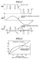
- the compensator terminal output voltage Since the compensator terminal output voltage has been generated on the basis of the modulation signal, the fundamental component of the output voltage looks the same as the modulation signal, as shown in Fig. 11b. However, the compensator terminal output voltage also contains harmonics, as shown in Fig. 11c. These harmonics are undesirable because actually the feeding of the voltage from the compensator terminals should only contain the fundamental component as shown in Fig. llb.
- the amount of harmonic component generation will of course depend on the modulation signal amplitude. For example when the amplitude of the modulation signal increases, there finally exists a case where the amplitude of the modulation signal exceeds the amplitude of the respective carrier signal all times such that the application of the capacitor voltage to the terminals 3a, 3b will be a square wave entirely corresponding to the shape of the fundamental component. That is, when the modulation index equals 1 then of course the content of the fundamental component will be larger than any harmonics components.
- Fig. 12 shows the fundamental amplitude and effective value (root mean square) of harmonics and it can be seen that the harmonics component varies in accordance with the modulation signal (fundamental component), i.e. more precisely with respect to the modulation index.
- the higher harmonics have a lower value than the fundamental component such that in a region between 0.65-1 (for the example investigated in Fig. 12) a modulation index control of the compensator output voltage can be used, i.e the amplitude of the modulation signal should be varied in accordance with the output voltage desired to be produced.
- the harmonics effective value is larger than the fundamental component in a low modulation index region (low fundamental component region) of ⁇ 0.65. Therefore, it would be preferable to select a constant modulation index control with a high modulation index of ⁇ 0.65 since then a sufficient harmonic suppression can be achieved.
- the constant modulation index control has other problems such as that the controllability of the DC voltage is degraded in zero or very low DC voltage region since the active voltage cannot be injected sufficiently into the line. Therefore, the constant modulation index control is not applicable for all values of the compensator terminal output voltage.
- a current controller 20 adjusts the DC voltage.
- the compensator terminal output voltage is zero, then also the DC control voltage is zero. In such a case it is not possible any longer to draw active power from the transmission line to the DC capacitor and the DC voltage cannot be controlled any more.
- the DC capacitor C DC must be charged by a battery or a pre-charge circuit.
- the United States Patent US 5,198,746 uses an absolute value circuit which clamps the voltage to a predetermined value even at the zero output terminal voltage of the inverter. Thus, controllability is maintained.
- the DC capacitor voltage goes to zero at a low compensator output terminal voltage if the DC voltage has perturbations in a single phase inverter.
- controllability of the output terminal voltage is reduced.
- the reason for these perturbations is that the DC current of a single phase inverter comprises second harmonic perturbations due to instantaneous power variations. Consequently, in the absence of a second harmonic filter in the DC circuit, also the DC voltage has a perturbation of the same frequency. If the amplitude of the DC voltage perturbation is larger than the mean value of the DC capacitor voltage, the instantaneous DC capacitor voltage goes to zero. Due to the use of anti-parallel diodes the inverter cannot provide a negative DC voltage and therefore the compensator terminal output voltage is not controllable when perturbations cause the DC capacitor voltage to drop below zero.
- the compensator terminal output voltage u c cannot only be controlled by the modulation index (i.e. the amplitude of the modulation signal) but also by changing the DC capaciter voltage u DC instead of the modulation index. The reason is that the compensator terminal output voltage u c depends on the magnitude of the capacitor voltage u DC .
- the compensator terminal output voltage u c can be controlled by the capacitor DC voltage and/or the amplitude of the modulation signal.
- the line current i can be controlled (increased/decreased) by the voltage (by the amplitude and the phase of the compensator terminal output voltage u c ) output by the compensator 3.
- Fig. 13 and Fig. 14 show examples of output voltage waveforms respectively for the constant DC voltage method and the adjustable DC voltage method.
- Fig. 15 shows the effects of the adjustable DC voltage control method.
- Fig. 15 shows the fundamental component and the harmonics component of the adjustable DC voltage with unitary modulation index. Since the waveform is similar to that of the unity modulation index in the whole region, the ratio of the fundamental wave and the harmonics component is the same for all modulation indices. Consequently, the harmonics component is always lower than a fundamental component and is less than that of the constant DC voltage control (i.e. variable modulation index control as shown with the dashed lines in Fig. 12 and 15).
- the harmonics of the line current entirely depend on the harmonics of the output voltage of the inverter. If the adjustable DC voltage method (i.e. constant modulation index) is used, the content of the harmonics will always be lower than the content of the fundamental component such that no problem arises.
- the adjustable DC voltage method i.e. constant modulation index
- the current in the inverter components is the same since this current is actually a line current i flowing through the line.
- the losses of the inverter components such as the tyristors and diodes intrinsically depend on the flowing current. If the switching frequency is reduced, the device losses are also reduced. However, if the switching frequency is reduced, the harmonics in the compensator terminal output voltage u c will be increased. Thus, the switching frequency cannot be reduced under a predetermined limit set by the maximum harmonics generation. Thus, during low loss operation of the inverter (lower switching frequency the value of which is limited to a lower limit) only the reducing of DC capacitor voltage can further reduce harmonics (if a constant temperature condition is assumed). In addition, the reduction of the DC capacitor voltage also reduces a leakage loss in a DC capacitance or components of the filters in the compensator.
- the current amplitude of the current i is mainly proportional to voltage u L over the inductance of the simplified transmission line 2a, 2b.
- the compensator 3 can change the voltage u L by injecting a compensation voltage u c at the compensator terminal output voltage.
- the change of the current amplitude is therefore proportional to the amplitude of injected voltage u c .
- the output of the current controller should have a linear relationship with the injection voltage u c . If the controller's output of the current control is proportional to the compensation voltage u c , the controller can operate linearily.
- the current controller can simply change its output mq (cc out ) to twice the value it had before. That is, the current amplitude is proportional to the (overhead voltage u x ) - (injected voltage u c ).
- the DC voltage at the capacitor may go to zero on this transient state.
- zero voltages must be avoided since the switching elements of the inverter can only handle positive voltages. Therefore, during a transient decrease of the reference voltage when using an adjustable DC voltage control of the line current, there is the additional problem of zero voltages at the capacitor.
- Fig. 16 shows the same dependency as indicated with the schematic lines in VDEP, CDEP in Fig. 10.
- Fig. 17b shows examples of the frequency characteristics of the transfer functions of Fig. 16 and different current amplitudes of the power transmission lines.
- the coupling from the active component of the modulation index m d to the current amplitude i d is larger than the main transfer function of the current amplitude.
- the other coupling has a larger gain at high frequency region compared to the main transfer function.
- the main transfer functions are varied by the operation point (in this case current amplitude), thus the control performance will be degraded using a control system as in Fig. 16.
- the coupling control of Fig. 10, 16 takes place independently as to whether a single-phase system or a three-phase system is considered.
- Fig. 17a shows the step responses of the basic control including the coupling control.
- the DC voltage is changed in a step function (in order to determine the dynamic coupling of the voltage to the current) there is a large pulse in the AC line current.
- a step function - similar change of the DC line current e d is performed, then - at time point 0.5 - a variation of the DC voltage also occurs. Therefore, also Fig. 17a illustrates that the voltage and current control cannot be performed independently in the conventional controllers for the transformerless reactive series compensator.
- the conventional controllers either operate with a variable modulation index and constant DC voltage or with a constant modulation index and variable DC voltage.
- the problem of harmonic generation in the compensator terminal output voltage still remains.
- the problem of the DC voltage dropping to zero which makes control impossible.
- there is the problem of switching losses and leakage losses of the capacitor There is also the problem of zero voltage in transient behaviours.
- the present invention has been devised to overcome the aforementioned problems.
- the main object of the present invention is to provide a controller which reduces the generation of harmonics in the compensator terminal output voltage and nonetheless avoids zero voltages.
- the control is performed on such a manner that the adjustable DC voltage control is used for a high output voltage region and the constant DC voltage control is used for the low output voltage region.
- the harmonics are reduced and in the low output voltage region the harmonics are still reduced compared to a constant high DC voltage control.
- Such a controller also avoids zero DC voltages at the DC capacitor and maintains a minimum DC voltage also for the continuous operation from capacitive to inductive mode or vice versa.
- the controller according to the invention also has the advantage of reducing the switching losses since at least at the adjustable DC voltage control a constant modulation index can be selected such that the switching frequency is as small as possible.
- the controller comprises a rate limiter for restricting the change rate of the predetermined voltage applied to the voltage control loop. This avoids steep drops of the capacitor DC voltage to zero in transient. Therefore, the rate limiter in the adjustable DC voltage region in particular solves the object of avoiding zero DC voltages in transient conditions, especially at a sudden change of the current reference.
- the controller further comprises decoupling control means receiving a modulation index m q ' from the current controller and a modulation index m d ' of the DC voltage controller and outputting new modulation indices m q and m d to the modulation signal generation means such that the line current is independent from the output md' of the DC voltage controller and the DC capacitor voltage is independent from the output mq' of the current controller, wherein the AC current amplitude and the DC capacitor voltage can be controlled independently.
- the decoupling control means is provided within the voltage and current control loops and is adapted to make the current control independent of the modulation index of the voltage control and to make the voltage control independent of the current modulation index. In combination with the rate limiter, this improves further the dynamic behaviour of the controller during sudden changes of the reference voltage in transient conditions.
- a first control method is a technique where the amplitude of the modulation signal m is changed which leads to a variation of the pulsewidth and thus to a variation of the output voltage u c (see Fig. 13).
- a second control method is a technique in which the output voltage u c is changed by changing the DC capacitor voltage u DC . Both methods have their problems regarding the generation of harmonics, the falling below zero of the DC capacitor voltage (preventing control and the taking of active power from the line) and switching losses.
- a controller according to the first aspect of the invention for avoiding these problems will be described with reference to Fig. 18a, Fig. 18b and Fig. 19.
- the current controller 20 outputs a control signal corresponding to the desired compensator terminal output voltage u c of the compensator. Furthermore, dependent on a predetermined reference voltage u DC ref the voltage controller 16 outputs the modulation index m d for said modulation signal.
- the coupling of the control method selection means SS to the voltage control loop allows to adjust the predetermined reference voltage u DC ref dependent on the current controller output cc out which indicates the desired compensator terminal output voltage.
- a combined control of the compensator terminal output voltage u c is possible by adjusting the modulation index mq (changing the amplitude of the modulation signal) and/or the reference voltage u DC ref (adjusting the amplitude of the DC capacitor voltage u DC ).
- Fig. 19 shows the function of the control method selection means SS. Since the output voltage can be controlled by both the DC voltage u DC as well as the modulation index m q , the selection means SS provides that the adjustable DC voltage control is used for a high output voltage region and the constant DC voltage control is used for a low output voltage region. The high voltage and low voltage region are separated by a predetermined compensator terminal output voltage threshold u cth , e.g. 20% of the maximum DC voltage.
- the control method selection means SS When the compensator terminal output voltage u c is smaller than said predetermined compensator terminal output voltage threshold u cth , i.e. u c ⁇ u cth , then the control method selection means SS outputs a substantially constant reference voltage u DC ref and a modulation index m q increasing and decreasing a depending on an increase or decrease of the compensator terminal output voltage u c as indicated by said current controller output cc out .
- the harmonics content In the low output voltage region u c ⁇ u cth the harmonics content is not as reduced as shown in Fig. 15, however, it is still reduced compared to the constant high DC voltage method indicated with the dashed line in Fig. 19.
- the constant DC capacitor voltage used in the lower terminal output region is set to such a value that even a maximum perturbation cannot cause a zero voltage, then a minimum DC voltage is maintained and thus the controllability of the output terminal voltage is ensured for the whole operating range.
- a constant modulation index is used which is set to a maximum modulation index m q max .
- this maximum modulation m q max must be an index which allows to reduce the effective value of the harmonics component to be smaller than the effective value of the fundamental component, and therefore, at such a modulation index m q max the harmonics component is always smaller than the fundamental component in the constant modulation index range.
- the main control loops of line current control and DC voltage control are interconnected via the signal separator SS which receives the output of the current controller cc out and which outputs the modulation m q and the DC voltage reference u DC ref .
- the line current is controlled by adjusting the output voltage and the control output signal cc out of the current controller 20 is separated to the DC voltage reference and the modulation index by the signal separator SS.
- the line current i is controlled not only by the modulation index but also by the DC voltage.
- control method selection means (signal separator SS) must ensure the minimum DC capacitor voltage by some limiting means and must adjust the modulation index to control the output voltage at the minimum DC voltage. In the higher output voltage region the current is controlled by DC voltage only and in the lower output voltage region it is controlled by the modulation index with the minimum constant DC voltage.
- Fig. 20 shows a first embodiment of a signal separator SS1.
- the control signal cc out of the current controller 20 which is input to the signal separator SS1 is the amplitude of the compensator terminal output voltage u c . Since the maximum output voltage u c of the compensator is basically the maximum DC capacitor voltage, also the output of the current controller cc out has a maximum value determined by the maximum DC capacitor voltage.
- a first limiter 200 is provided for limiting the control voltage cc out to a voltage level u DC min when the control voltage cc out exceeds this predetermined limit voltage u DC min . Likewise, if the control voltage cc out falls below the negative limit voltage -u DC min then the control voltage cc out will be limited to this negative limit voltage u DC min . Furthermore, a first divider 201 is provided for multiplying the output of the first limiter 200 with the maximum modulation index m q max and for dividing the result by the first limit voltage u DC min . The output of the first divider 201 is the modulation index mq. Thus, in the upper signal part 200, 201 in Fig.
- a variable modification index mq increasing and decreasing (e.g. linearily) with an increase or decrease of the control voltage cc out is output.
- the limit voltage u DC min corresponds to the threshold voltage u cth as explained with reference to Fig. 19.
- a first absolute value circuit 202 is provided for determining the absolute value of the control voltage cc out .
- a second limiter 203 is provided for setting the reference voltage u DC ref to a minimum voltage U DC min if the output of the absolute value circuit 202 falls below this lower voltage value u DC min .
- the second limiter 203 is also adapted for limiting the output of the absolute value circuit 202 to an upper threshold value u DC max .
- the limiter 203 in the lower path outputs the minimum DC voltage which thus corresponds to the constant DC voltage control method, i.e. a variable modulation index depending on the gain of the limiter 200 is output whilst a constant DC voltage is set via the constant reference voltage u DC ref .
- a control voltage cc out exceeding the minimum voltage u DC min the control voltage cc out multiplied with the gain of the second limiter 203 is output as the reference voltage u DC ref .
- the adjustment of the gain of the limiters 200, 203 is preferably adapted to the control behaviour of the current control loop and the voltage control loop (PI, PID etc.).
- m q max is preferably selected to be +1. However, other values are possible. If m q max ⁇ 1 the modulation index for the current control is limited less than 1 and the inverter can additionally output voltage for the DC voltage control. That is, the maximum output voltage is limited by the DC capacitor voltage and the output voltage is maximum at the modulation index being one in the PPM method as shown in Fig. 11. If the current controller 20 outputs the maximum modulation index and the DC capacitor voltage requires to take power from the transmission line, a sinusoidal modulation signal m in Fig. 11 will exceed 1 and as a result the output voltage will be distortet.
- the modulation index m q max is selected to be less than one, a control margin to control the DC voltage is possible.
- the modulation index maximum value must be selected to be a value which ensures that the effective value of the harmonics component is smaller than the effective value of the fundamental component (see Fig. 12 and Fig. 19).
- FIG. 21 A second embodiment of a signal separator SS2 having the control characteristics as shown in Fig. 22a is shown in Fig. 21.
- This signal separator SS2 comprises a third limiter 211 for limiting the control voltage cc out output by the current controller to a maximum modulation index m q max and a minimum modulation index m q min when the control voltage cc out respectively exceeds or falls below the maximum and minimum modulation indices, respectively.
- cc out is the modulation index level.
- the maximum modulation index m q min may be the negative value of m q max .
- the signal separator SS2 comprises a second absolute value circuit 213 for determining the absolute value of the control voltage cc out .
- a first multiplier 212 multiplies the output of the absolute value circuit with a predetermined constant K 2 .
- a fourth limiter 214 limits the output of the second multiplier 212 to an upper threshold value u DC max and a lower threshold voltage u DC min when the output of the second multiplier 212 respectively exceeds said upper and lower threshold voltages u DC max , u DC min .
- the first multiplier 212 uses a predetermined constant K 2 for converting the control voltage cc out into the DC voltage reference level.
- the predetermined constant K 2 can also be incorporated as part of a gain of the fourth limiter 214.
- the constant K 2 is part of the absolute value circuit 213 which in this case comprises a gain factor corresponding to the constant K 2 .
- the signal separators SS1, SS2 enable a control with the constant DC capacitor voltage and a variable modulation index in a low voltage output region and with a constant modulation index and variable DC capacitor voltage in the higher output voltage region thus avoiding harmonics in the output voltage at the terminals 3a, 3b. At least in the higher output voltage region a selection of a modulation index will also allow to reduce switching losses. In any case zero DC capacitor voltage is avoided thus allowing the taking of active power from the transmission system into the DC capacitor.
- the current controller output cc out designates the desired terminal voltage at the compensator and the DC voltage controller will maintain the DC capacitor voltage such that the control voltage cc out equals the compensator terminal output voltage u c in the adjustable DC voltage region.
- a steep change in the reference voltage u DC ref could cause an undershoot of the DC capacitor voltage and a zero DC capacitor voltage could occur as a result of the undershoot.
- a change of the control voltage cc out (horizontal axis) and hence a change of the reference voltage u DC ref from A ⁇ B may cause (depending on the dynamic behaviour of the voltage control loop) - an undershoot such that the DC capacitor voltage u DC may become zero.
- the undershoot is a result of the steep and fast decrease of the controller voltage cc out .
- the current amplitude is mainly proportional to the voltage u 1 over the inductance of the simplified transmission line.
- the compensator can change the voltage u l by injecting a compensating voltage u c .
- the change of the current amplitude cc out is therefore proportional to the amplitude of the injected voltage.
- the output voltage cc out of the current controller is desired to have a linear relationship with the injection voltage u c . If the output of the current controller is proportional to the compensation voltage, the controller can operate linearily.
- the current controller should simply change its output cc out to twice the previous value since the current amplitude is proportional to ((overhead voltage u x )-(injected voltage u c )).
- the modulation index mq still keeps constant and the u DC voltage does not follow the desired output signal cc out if the rate limiter is placed before the signal separator.
- the q-axis modulation index mq would start changing earlier and would not be kept constant between t 0 to t 1 '.
- the rate limiter is effective for a safe operation in constant mq operation, but degrades the transient performance.
- the placing of the rate limiter only at the voltage reference u DC ref that is, breaking characteristics of Fig. 22(a) in the transient condition, helps recovery of the transient performance.
- the third limiter is actually the circuit that restricts the change rate of the input signal.
- a third multiplier 252 multiplies the output of the third limiter 255 by the predetermined sampling time T s .
- a second adder 253 having an input receiving the output of the third multiplier 252, a second input and an output constituting the output of the rate limiter is provided.
- the unit 254 is (in discrete sampling time) a unit-sample delay unit for shifting the output of the rate limiter to one sampling time.
- the output of the z -1 circuit 254 is applied to the second input of the first adder 266 and a second input of the second adder 253. If the input is a time discrete signal as shown in Fig. 25b, the output will be the discrete time signal also shown in Fig. 25b.
- the multiplication constant K2 is determined by the ratio of the lower threshold voltage u DC min divided by the maximum modulation index m q max as used in the limiter 261 in the upper signal path.
- the rate limiter restricts the rate of the reference voltage to avoid a steep drop of the DC voltage to zero in transient conditions, especially at a sudden change of the current reference.
- the negative rate is selected slower than the positive rate. That is, the rate limitation for the positive rate change is larger - in absolute value - than the rate change allowed for changes in the negative direction.
- the control trajectory first moves into a horizontal direction from A' to C as shown in Fig. 24b. Then the control trajectory moves down to the steady state point B'.
- the desired control trajectory in the constant DC voltage control region is a direct path from A' to B'.
- the fact that an operation is out of the desired control trajectory can also happen without the rate limiter when the DC voltage does not follow its reference due to a slow response behaviour.
- the provision of the rate limiter enhances this problem.
- the result of the introduction of the rate limiter is that the injection voltage u c is not proportional to the control voltage cc out - even in the control region where only the variable DC capacitor control is used.
- the dashed line indicates the ideal response which is still proportional to the control voltage cc out despite the provision of the rate limiter.
- the signal separator SS can be used in connection with such a decoupling control means 25.
- the signal separator SS may or may not contain the rate limiter.
- the rate limiter is used this further deteriorates the response behaviour of the control loops and the use of the decoupling control will be particularly advantageous.
- Fig. 27b shows the third aspect of principle block diagram of a controller according to the invention.
- the inventive controller comprises a current detector 24 and a current control loop formed by the feedback path 21, 18 and the forward path including the current controller 20.
- a voltage control loop comprises the voltage detector 26, the feedback path 15 and a forward path comprising the DC voltage controller 16.
- the inventive controller comprises a decoupling control means 25 downstream of the current controller 20 and the DC voltage controller 16.
- the decoupling control means 25 outputs a first modulation control signal m q for controlling the line AC current i and a second modulation control signal m d for controlling the compensator output voltage.
- the first and second control signals m q , m d are selected such that a change in the first control signal mq will not influence the DC control voltage u DC , i.e. such that the capacitor voltage u DC is independent of the control signal m u output by the current controller 20.
- the second control signal m d is selected such that it does not influence the line current, i.e. the line current i is independent from the second control signal m d .
- the decoupling control means 25 must perform some kind of inverse operation such that the coupling effects due to the current transfer function block CTF, the voltage transfer function block VTF, the voltage current transfer block VCTF and the current voltage transfer function block CVTF are canceled. That is, if the current controller 20 and the voltage controller 16 operate as in the conventional system in Fig. 10, then the decoupling control means 25 will output some kind of predestorted modulation indices m q' , m d' which - when transferred through the blocks CTF, VCTF, CVTF, VTF will precisely cancel the effects of these blocks. In particular, the decoupling control means 25 allows to get rid of the cross-coupling blocks VCTF, CVTF which cause the coupling of the current control loop and the voltage control loop.
- equation (4.9) can be considered as a non-linear differential equation of m d it is not possible to realize this equation in an on-line controller because the coefficient of the derivative is i q which takes positive or negative values around zero.
- the time derivative of m d in equation (4.9) can be ignored such that the modulation m d can be calculated as follows:
- equation (4.11) and (4.10) a perfect decoupling control can not be realized since these equations still depend on the circuit parameters such as resistance, inductance and capacitance.
- equation (4.10) the main coupling is still the time derivative of m d . .
- Fig. 28 shows the controller according to Fig. 9 (i.e. including an AC voltage detector 23, a voltage PLL phase detector 18 and the phase rotation means 17) but also including - according to the fifth embodiment of the invention - a decoupling control means 25.
- the decoupling control means 25 receives the output (modulation index) mq' of the current controller 20, the DC capacitor voltage u DC , the current amplitude i d , the line frequency ⁇ and the output m d ' of the DC voltage controller 16.
- the decoupling control means 25 receives the output (modulation index) mq' of the current controller 20, the DC capacitor voltage u DC , the current amplitude i d , the line frequency ⁇ and the output m d ' of the DC voltage controller 16.
- the decoupling control means 25 the compensator 3, the 2f-filter 15 and the DC voltage controller 16 is provided three times.
- the current detector 24 i.e. the current detector 24, the current amplitude and phase detection units 21, 18, the capacitor voltage detector 26, the mean voltage detector 15, the reference phase generation unit 17 (keeping i q in the control system 0), the reference frame detection 18, the coordinate transformation 19, the DC ripple compensation unit 13 and the voltage phase detector 23 correspond to those units already described in Fig. 9.
- the resulting AC current and output voltage of the compensator without the DC voltage fluctuation means 13 and the 2f filter 15 include some harmonics, however, the decoupling control is effective even without these units. These units can preferably used in certain applications to suppress the harmonics. For example, if the capacitance of the DC capacitor is large enough to suppress the fluctuation then no additional units are needed. Alternatively, if the 2f filter (e.g. an LC filter) is configured with the DC capacitor in parallel in the DC circuit of the compensator 3, the units 13, 15 are again not needed. The latter solution is practically a realistic solution for the transformerless series compensator.
- the 2f filter e.g. an LC filter
- the output m d ' is multiplied with the constant K d in the multiplier 25j.
- K d the constant K d in the multiplier 25j.
- the equations (4.16), (4.17) can be rescaled such that K d is 1 such that the additional multiplier 25j is not necessarily needed, i.e. K d can be unity.
- the output mq' of the current controller is multiplied with the constant Kq in the multiplier 25k (Kq can also be unity due to a normalization).
- the multiplied signal N1 forms the nominator of the first divider 25a.
- the detected DC voltage u DC is multiplied by the reference frame frequency ⁇ in the multiplier 25b.
- the multiplied signal D 1 is the denominator used for the division in the divider 25a.
- the output DV1 of the first inverter is supplied to an adder 25i.
- the line frequency ⁇ is the denominator for the division in the second divider 25c and a signal N2 output from the filter is the nominator of the second divider 25c.
- the multiplied signal DV2 is applied as inverted input to the adder 25i.
- the main loop of the capacitance voltage control is designed to a limited band width in its frequency characteristics, placing a filter 25f with a small time constant in the main loop does not affect the characteristics of the main loop.
- the integrator 25h, the gain 25g and the subtractor 25f act together as filter and the input of the filter is the pure differentiation of m d with respect to time. Therefore, this coupling can perform a compensation properly by a pure differentiation using the filter function.
- the coupling of the other side which is compensated by division of the current is also filtered.
- response of the current is also limited because of the inductance of the transmission lines and responses of the feedback control of the current amplitude.
- the filter 25f, 25g, 25h having a small time constant T f in the main loop does not affect the characteristics of the main loop.
- the integrator 25h, the gain 25g and the subtractor 25f act together as the filter and the input N 2 of the integrator 25h is the pure differentiation of Md with respect to time.
- the input of the integrator 25h forms the nominator M 2 of the divider 25c.
- Fig. 31a shows by contrast to Fig. 17a of the prior art the step responses using a decoupling control. Whilst at time point 0.1 in Fig. 17a the current amplitude i d shows a ripple due to coupling, there is no change whatsoever if a voltage step occurs in Fig. 31a at time point 0.1. Likewise, if the current has a step at time point 0.5 in Fig. 31a, there is no variation of the voltage at all. Thus, Fig. 31a shows that the current end voltage can be controlled independently on the basis of the equations (4.16), (4.17).
- Fig. 28 together with Fig. 29 shows an embodiment of the invention comprising a three-phase system using a voltage PLL and an independent and local control
- the controller does not need a AC voltage detector 26 shown in Fig. 28.
- the configuration of the sixth embodiment is therefore constructed like Fig. 28 and omitting the voltage detector 23 and the phase rotation means 17 and connecting the output of the current detector 24 also to the phase detector 18 which now acts as a current PLL unit 18.
- the three-phase polar transformation unit 21 is the same as in Fig. 28 and the phase detector 18 directly outputs the sin ⁇ and cos ⁇ functions.
- the fifth embodiment the fifth embodiment.
- Fig. 30a shows a single phase system having the basic construction of Fig. 8 and having a decoupling control means 25 and a component detector 26 according to a seventh embodiment of the invention.
- the current detection is also phase. Since the current detection is single phase, it is not possible to provide the q-axis component of the current iq to be zero by a reference frame detection. Therefore, in Fig. 30a the equations shown in Fig. 27c, namely equations (4.14), (4.15) are realized.
- a single phase to d-q coordinate transformation of the current is needed (see Fig. 30b) in order to provide the i d and i q components needed in the decoupling control means 25 as shown in Fig. 30a.
- the decoupling control means 25 comprises, in addition to the units 25a-25k an additional multiplier 251 and an additional adder 25m.
- the multiplier 251 multiplies the q-axis current component iq with the output of the first divider 25a and feeds a multiplied output ML to the negative input of the adder 25m.
- the adder 25m subtracts i q *DV 1 (i.e. i q *m q 'K q /u DC ⁇ from m d 'K d ).
- the output of the adder 25b forms the nominator signal M 3 of the third divider 25d. With such a configuration the full equations (4.14), (4.15) can be realized.
- Fig. 30b The AC line current i detected by the current detector 24 is multiplied by the sinusoidal reference signals cos( ⁇ t) and sin( ⁇ t) which are produced by the phase detector 18.
- the component detector 26 comprises a first and second multiplier 26a, 26b for multiplying the detected line current i with the signals sin( ⁇ t) and cos( ⁇ t) to produce the orthogonal current components i d , i q .
- the reference signal cos ( ⁇ t) is a signal in-phase to the AC current, and therefore icos ⁇ t and isin ⁇ t include the amplitude of the AC current i d and the transient component i q , respectively.
- the component detector 26 outputs the i d and i q components.
- the 3-phase-polar transformation unit 21, the phase detector 18 and the phase rotation unit 17 correspond to those units already described with reference to Fig. 28. It is interesting to note that the decoupling control of the single-phase system with the voltage PLL version can be simplified just like in the case of the three-phase system with voltage PLL in Fig. 28 and Fig. 29. Because there is employed a phase correction from the voltage phase to the current phase this control makes the decoupling just a simple as in Fig. 29. Of course, by contrast to Fig. 28, there is an additional delay in the control loop because of the component detection in the component detector 26. However, the decoupling control 25 operates with the corrected reference frame in which the q-component of the current is made zero.
- a further filter 27 can be used for filtering the input reference voltage u DC ref .
- Such a filter 27 can also be used in each of the fifth, sixth and seventh and eighth embodiments as illustrated in Fig. 18-32 and explained above.
- the filter has the effect of reducing the amplitude of the modulation index and thus a decoupling control is achieved with a restricted output voltage capacity. Since the high frequency components of the input reference voltage are reduced by the filter, these components are not transferred to the decoupling control units. As a result, the output of the gain unit 25g will be reduced. This means, if the gain of the DC voltage controller is low and/or the input reference voltage is slow, the decoupling control unit DV2 can be neglected.
- a voltage PLL is used because the usage of the voltage PLL is generally known.
- the sixth embodiment has no voltage PLL and its advantage is a reduction of components.
- the seventh embodiment uses no voltage PLL to illustrate simply the application of the invention in a single phase system.
- the single phase system can operate with the voltage PLL and the voltage detector as shown in Fig. 32b according to the eighth embodiment.
- the additional filter according to the nineth embodiment can be used in any of the other embodiments. Of course the embodiments can be combined.
- the 2f filter and the DC voltage fluctuation compensation means are optional units as explained above.
- the signal separator SS in accordance with the first and second aspect of the invention can be used in connection with the decoupling control means. That is, the current controller 20 outputs the control voltage cc out and the signal separator outputs the modulation index mq' whilst the decoupling control means outputs new modified modulation indices mq and m d as explained above.
- Fig. 33a shows a similar block diagram as Fig. 33a, for a single phase system.
- a preferable signal separator to be used in Fig. 33a, 33b is illustrated in accordance with the eleventh embodiment in Fig. 34. It comprises in the lower signal path an absolute value circuit 341 and a limiter 342 and a rate limiter 343 which perform the similar functions as the units 233, 234 and 235 in Fig. 23.
- the modulation index mq' output by the signal separator SS5 is the control voltage cc out .
- the dynamic characteristics are shown in Fig. 35a and Fig. 35b. Whilst the control trajectory goes from point A' to point B' through C, in Fig. 35a and Fig. 35b the control trajectory of the modulation index mq directly moves from A' ' to B' ' due to the decoupling control. As shown in Fig. 35b, this means that the modulation index is not constant in transient and consequently the output terminal voltage (in the lowest diagram in Fig. 35b) is directly proportional to cc out which equals mq'. Therefore, the current response can be improved by the signal separator in Fig. 34 together with the decoupling control.
- a rate limiter is used in the lower signal path, as shown in Fig. 23, Fig. 26 or Fig. 34, possibly combined with a decoupling control.
- the rate limiter is only inserted into the control path for the adjustable DC voltage control.
- any controller which does not even use the first aspect of the invention i.e. a controller which uses the conventional DC adjustable control method over the complete compensator terminal output voltage range will benefit from the use of a rate limiter and possibly of the use of a rate limiter together with a decoupling control. That is, any controller in Fig. 18a which outputs a permanently constant modulation index m q but which outputs a variable DC reference voltage u DC ref may only use the lower signal path elements in Fig. 23, 26 and Fig. 34, possibly in combination with the decoupling control means. This will allow in a controller which only uses the adjustable DC voltage control method to avoid zero voltages when there is a sudden large decrease in the current controller output cc out .
Abstract
Description
- The invention relates to a controller for controlling a reactive series compensator serially inserted at compensator terminals into a power transmission line. Typically, in such a transformerless reactive series compensator an inverter control is performed in order to control the line current and/or the voltage applied from the compensator to the transmission line. The voltage/current control enables to control the power flow of power from one end to the other end of the transmission line and to perform a power flow into the inverter of the compensator in order to charge a capacitor which provides a compensator terminal output voltage at the compensator terminals.
- Typically, as will be explained below with more details below, a current feedback control loop and a voltage feedback control loop are employed in order to respectively control the reactive and the active part of the line current. For doing so the modulation signal based on which the PWM control of the inverter is performed is a sinusoidal signal of a particular phase. Adjusting the amplitude and the phase of the modulation signal allows to perform the power control.
- Using such control loops the output voltage of the compensator can be controlled by a modulation index with a constant DC voltage. Alternatively, the output voltage can be controlled by the DC voltage only using a constant modulation index, as the paper by A. Beer, H. Stemmler, H. Okayama, "Hybride Transformerless Reactive Series Compensators", EPE 1999 - Lausanne describes (see
page 8 of this paper). However, using constant DC voltage, the injection of harmonics into the transmission line by the inverter cannot be reduced even if the fundamental component is smaller than the DC voltage. Furthermore, using constant modulation index control, the controllability of the DC voltage is degraded in zero or very low DC voltage region since the active voltage cannot be sufficiently injected into the transmission line. Therefore, this method is not applicable to a full range operation. Furthermore, with the aforementioned two different control methods it is also difficult to reduce DC voltage dependent losses such as the switching loss of switching elements of the inverter and leakage loss of the DC capacitor of the compensator. - The present invention in particular addresses the problem as to how the injection of harmonics by a compensator controlled by a controller including a current and voltage control loop can be reduced. The present invention also addresses the ether aforementioned problems.
- Hereinafter, first the general background of transformerless reactive series compensators and of controllers for controlling a compensator and comprising a current and voltage control loop will be described.
- Recently, power electronics equipments for flexible AC power transmission systems (FACTS) have been investigated and applied to practical systems. A transformerless reactive series compensator is one of these equipments and is effective to perform a power flow control as was explained above. Since the transformerless reactive series compensator does not comprise the transformer its size is small and it can be advantageously used.
- Fig. 1a and 1b respectively show a typical configuration of a power transmission system comprising two AC power systems la, 1b coupled to each other through
power transmission lines series compensator 3 need to be provided, in the three-phase system a plurality ofseries compensators 3 are respectively serially inserted as shown in Fig. 1b.Reference numerals - As shown in Fig. 2, a
typical series compensator 3 comprises astarting switch 4, a filter 12, aninverter 7, a DC capacitor CDC, a control means C, a saw-tooth generator 10 and a modulation signal generation means 11. Theinverter 7 comprises fourthyristors - Whilst the expression "thyristor" is usually a device whose turn-off is not controllable, in Fig. 2, since a PWM is used for the inverter, a gate turn-off type thyristor is employed. Since a GTO (gate turn-off thyristor), a GCT (gate commutated thyristor) and an IGBT (insulated gate bipolar transistor) are also generally be possible for operating as the kind of switching power device in Fig. 2, hereinafter it is assumed that the expression "thyristor" comprises all such switching power devices.
- Each thyristor has connected anti-parallely thereto a
diode reactors 9b, 9a. and acapacitor 8 for filtering higher order harmonics which are generated by the PWM control of theinverter 7. The filter terminals are connected to the respective interconnections of thethyristors 5a, 5b and of thediodes thyristors diodes 6c, 6d. The DC capacitor CDC is connected at the other terminals of the thyristors and the diodes. - The circuit configuration of the
series compensator 3 is conventional and is for example described in the European patent applications No. 98 116 096.3, No. 98 106 780.4 and No. 99 124 851.9 by the same applicant. These patent applications in particular describe the start and stop control of theseries compensator 3 and a decoupling control. - A PWM control of the
inverter 7 is carried out as principally shown in the diagram of Fig. 3. A modulation signal generation means 11 in Fig. 2 generates a sinusoidal modulation signal m and the saw-tooth generator 10 outputs two saw-tooth carrier signals csl, cs2. A PWM control signal SW5a, SW5d is generated by comparing the modulation signal m with the respective carrier signal csl, cs2. That is, when the modulation signal amplitude is larger than the carrier signal csl amplitude then the PWM switching signal SW5a is on and it is off if the modulation signal amplitude is smaller. Similarly, if the amplitude of the modulation signal is larger than the inverted carrier signal cs2 then the other PWM switching signal SW5d is switched from ON to OFF. The PWM signals SW5a, SW5d are used to trigger thethyristor 5a, 5d. It should be noted that of course a similar control applies to thethyristors - Assuming that the DC capacitor CDC was charged to uDC the output voltage uc at the
connection terminals 3a, 3d will have a waveform as shown in Fig. 3 in the bottom graph. It will be appreciated that by changing the respective amplitudes of the modulation signal and/or the carrier signal and/or by changing the phase of the modulation signal and/or the carrier signal, different waveforms of the output voltage uc (hereinafter also called the inverter terminal voltage or compensator output voltage) can be achieved. Comparing Fig. 3 with Fig. 2 it can be seen that essentially the output voltage uc is the voltage applied to theterminal - Whilst from Fig. 3 it only appears as if the terminal voltage uc changes due to the PWM control of the
inverter 7, of course the line current i would also change since current and voltage are linked through the coupling effects due to the line impedance LAC. The simultaneous effects of the PWM control on the line voltage and the line current will be explained now. - Fig. 4a shows a summary diagram of the essential parts of Fig. 2 necessary for explaining the current and voltage control. Fig. 4b shows the principle phasor diagram for Fig. 4a. As was the case in Fig. la, also in Fig. 4a the
compensator 3 is serially connected between thepower transmission lines AC power systems reference numeral 7 has been attached. A modulation signal m is applied in order to perform the PWM control. uL is the voltage occurring as a result of the line impedance LAC, i is the line current, iDC is the current flowing through the DC capacitor CDC, uDC is the voltage over the DC capacitor CDC and uc is the output voltage of theseries compensator 3. Furthermore, ux is the overhead voltage which is a difference voltage between the AC sources. For simplicity reasons the leakage conductance in the DC side which could include the switching losses, leakage losses of capacitors and/or losses of DC filters (essentially a parallel resistance to the DC capacitor CDC is not necessary to be considered for the phase relationships. - Fig. 4b shows a principle phasor diagram and the voltages explained with reference to Fig. 4a are shown therein. The
compensator 3 can output an output voltage uc of arbitrary phase with limited amplitude using the DC capacitor voltage uDC. - Fig. 5(a), 5(b) and Fig. 5(c) respectively show the cases for no compensation, capacitive operation and inductive operation when controlling the line current i. That is, when the
compensator 3 injects a zero voltage uc into the line, then the inductance voltage uL is the same as the overhead voltage ux (Fig. 5(a)). In this case, the line current i flows through the transmission line with a 90° phase lag with respect the inductance voltage uL. - When the
compensator 3 injects a capacitive voltage uc which leads 90° to the line current i, then the inductance voltage uL increases and therefore also the line current i is increased (Fig. 5(b)). - On the other hand, when the
compensator 3 injects an inductive voltage to the line (uc is in-phase with the inductance voltage uL), the inductance voltage uL is decreased and therefore also the line current i is decreased (Fig.5(c)). Thus, the first purpose of thecompensator 3 is that the line current i can be controlled (increased/decreased) by the voltage (by the amplitude and the phase of the compensator output voltage uc) output by thecompensator 3. Furthermore, of course a skilled person realizes what has been described above for a single phase can be performed in the same manner for a three-phase system. - Of course, the control in Fig. 5 can only be carried out if the DC capacitor CDC has been charged to the predetermined voltage uDC since otherwise no injection of voltage would be possible into the line. Instead of using a battery or another power source, it is advantageous to also control the
compensator 3 such that a power flow from the line to the DC capacitor CDC is effected. Such a charging or active power flow from the line to the capacitor is explained with reference to Fig. 6 and Fig. 7. - As mentioned before, a charging of the DC capacitor CDC requires an active power flow from the
transmission lines inverter 7. In order to take the active power from thepower system compensator 3 has to feed the active component of the applied AC voltage uc to the DC capacitor CDC. - In steady state conditions, as already explained with reference to Fig. 5(c) and as shown also in Fig. 6(a), the
compensator 3 outputs a reactive voltage uc which has a 90° difference phase to the line current i. This situation is present in the initial state and the final state of charge control as shown with Fig. 6(a) and 6(c). - When the
compensator 3 outputs the active component in a short duration for taking in active power, the inductance voltage is also changed transiently as shown in Fig. 6(b). The transient inductance voltage includes a di/dt component and a ωLi component. When the di/dt component is generated, the ωLi component is influenced. Then, the variation of the ωLi component influences the di/dt component and the line current fluctuates in an oscillation manner as shown in Fig. 6(b). Consequently, the charging process does not only influence the capacitor voltage but also the line current. The reason is the coupling effect through the line inductance LAC as can be understood from considering the dynamic behaviour of the currents and voltages. - Namely, a voltage equation of the inductance LAC can be written as follows.


- It can now be understood, as shown in Fig. 6(b) that if Ud (the active part of the applied voltage) is changed, then also Id (the active part of the current) varies and Iq (the reactive part of the current) is also influenced.
The coupling of a line current control to a DC voltage is illustrated in Fig. 7. A rapid change of the reactive component of the compensator voltage by the line current controls generates a di/dt component of an inductor voltage. Therefore, the line current phasor i moves towards the direction of the change first. Then, the ωLi component and di/dt component influence each other with the same mechanism but opposite coupling. As a result, the line current has a fluctuation and an active component which is a in-phase component to the compensator voltage. This active component now causes an active power flow from the power transmission line to the DC capacitor CDC in the transient state as shown in Fig. 7(b). However, if the line current is controlled, obviously also the DC voltage is influenced by the line current control. - As can be understood from the above description of Fig. 4, 5, 6, 7, the main purpose of a controller for the series compensator is to perform a control to increase/decrease the line current as shown in Fig. 5 and to charge the DC capacitor CDC by allowing an active power flow to the DC capacitor CDC as in Fig. 6, 7. Such controllers will be explained hereinafter.
- Fig. 8 and Fig. 9 show controllers for a single phase and three-phase system, respectively. Such controllers comprising essentially a current loop and a voltage loop are known from "Hybrid transformerless reactive series compensators" Proceedings of the 8th European Conference on Power Electronics and Applications Conference (EPE) - Lausanne 1999, pages 1-10. The principle control scheme of a single phase system will be explained below with reference to Fig. 8.
- The
series compensator 3 has the configuration as already explained above with respect to Fig. 2 or 4. It is connected serially into thepower transmission lines compensator terminals compensator 3 is controlled by a modulation signal m. Acurrent sensor 24 senses the line current i and avoltage sensor 26 senses the DC capacitor voltage uDC. - The following relationship between the currents and voltages exist (where also the line resistance RAC is included) as illustrated with the following equations.


- Again introducing the reference frame ω in the steady state case as in equation (1.2) and (1.3) leads to:


- Of course, a skilled person realizes that these equations are the same as phasor expressions in the complex plane in the form of e.g. i = Re[(id + jiq) ej ωt]. Inserting equations (2.3) - (2.5) into equation (2.1), the following equation can be obtained:

- In order to obtain the dynamic equation of the AC current in the rotational reference frame ω the coefficients of the cosine and sine functions are derived:


- Equations (2.7) and (2.8) respectively describe the current dynamics. The DC voltage dynamics in equation (2.2) can be related to the AC current dynamics using a balance of power on the AC and DC side. Of course, the output voltage uc at the
output terminals compensator 3 is directly related to the modulation m applied to theinverter 7. Therefore, in principle the output voltage uc of thecompensator 3 has the following relationship with the modulation signal m:
- Again introducing the reference frame ω and applying the reference frame also to the modulation signal as m = md cos(ωt) - mq sin (ωt) the following relationship for the amplitudes must exist:


- Inserting equations (2.10) and (2.11) into equations (2.7) and (2.8) leads to:


- Since the instantaneous AC active power of the compensator PAC = uc*i and the DC power pDC = uDC*iDC must be balanced under the condition of no losses in the converter, the DC current can be written as:


- The DC voltage dynamics can thus be obtained by substituting equation (2.14) into equation (2.2) leading to equation (2.16) as follows:

- The above equations in particular equations (2.12) and (2.13) show that the AC current (id and iq) and the DC voltage (uDC) can indeed be controlled via the modulation signal (md and mq), that is via the modulation indexes md and mq. Also equation (2.16) shows that this is possible.
- A basic controller consisting of two feedback control loops in a system where one is the AC current amplitude control and another one is the DC voltage control based on the modulation indices as derived with the preceding equations is shown in Fig. 8. Since the reactive series compensator can control only reactive power in steady state and the q-axis component in the AC current is kept zero by a phase locked
loop 18, mq is related to inductive and capacitive voltage and is used for controlling the AC line current amplitude. The DC voltage is controlled by md because it is related to active power and is the only available signal at iq = 0 in equation (2.16). - Fig. 8 shows a block diagram of a basic control of the series compensator. This controller consists of the
current controller 20 with theamplitude detector 21, theDC voltage controller 16 with thefilter 15, the current phase detector (PLL) 18, the coordinatetransformation unit 14 and the compensation of a DC voltage fluctuation by the DC voltage fluctuation compensation means 13. - In principle, the controller shown in Fig. 8 performs a control as specified with the above mentioned equations (2.12), (2.13), (2.16). The
amplitude detector 21 detects the current amplitude of the line current i as sensed by thecurrent detector 24.Reference numeral 22 designates a subtractor which subtracts the command value id ref from the amplitude detector output value id.Reference numeral 20 designates the current controller, e.g. a PI or PID controller which outputs the real part mq of the modulation signal. -
Reference numeral 15 designates a filter for filtering the second harmonics of the fundamental frequency.Reference numeral 19 designates a subtractor for subtracting the output of thefilter 15 from the voltage command uDC ref.Reference numeral 16 denotes a DC voltage controller, i.e. a PI or PID controller which outputs the imaginary part md of the modulation signal m. - As explained above,
reference numeral 18 designates a phase detector (e.g. a phase locked loop PLL) which outputs reference signals sin(ωt), cos(ωt) locked to the phase of the line current i as detected by thecurrent detector 24. As explained above, basically thereactive series compensator 3 outputs a reactive voltage uc and for this reason somehow the control system needs an input about the phase of the AC line current i. In Fig. 8, in the single phase system, a direct measurement of phase using AC current i is employed. Thephase detector 18 is contains a phase locked loop PLL which produces the cosine and sine function of the phase. -
Reference numeral 14 designates a coordinate transformation means including a first andsecond multiplier Reference numeral 14c designates a subtractor which subtracts the output of thefirst multiplier 14a from the output of thesecond multiplier 14b. The output is a modulation signal m0 which is a complex signal. -
Reference numeral 13 designates as mentioned before, a DC voltage fluctuation means which includes amultiplier 13a and adivider 13b. Themultiplier 13a multplies the output signal from thesubtractor 14c with the output from thedivider 13b and outputs the modulation signal m. Thedivider 13b divides the output from thefilter 15 by the input of thefilter 15. Thefilter 15 and theunit 13 are optional although their use can advantageously reduce the effect of harmonics. - The above described units form two control loops for the current and the voltage based on the sensed current i and the sensed DC capacitor voltage uDC.
- The current control loop outputs the q-axis modulation index mq to control the amplitude of the AC current using a feedback control. The
current controller 20 modifies mq in a positive direction when the measured current amplitude id is larger than the reference value to move to a smaller current operating point. When the measured current amplitude id is smaller than the reference value, the operation is performed in an opposite direction. Therefore, thesubtractor 22 just before thecurrent controller 20 has a negative sign for the reference signal id ref. Theamplitude detector 21 is preferably a peak detector, a rectifier and so on for a single phase compensator. - The
voltage controller 16 on the other hand outputs the active component md of the modulation signal m for controlling the DC voltage of thecompensator 3. When the DC voltage goes down, thevoltage controller 16 will increase md such that the active power component of the AC voltage of thecompensator 3 increases and a power influx from the AC system into the DC capacitor is effected. When the DC voltage uDC increases, md will be modified by theDC voltage controller 16 in a negative direction. There is a fluctuation which has two times the fundamental frequency in the DC voltage caused by varying of a single phase AC power in one cycle. To reduce the fluctuation in the controller, thedetection filter 15 can preferably be provided, because this frequency is normally much higher than the dominant frequencies of the voltage control loop. - The
phase detector 18 detects or follows the phase of the AC current i in order to provide one reference sinusoidal signal sin (ωt) in phase-and another one cos(ωt) orthogonal to the AC current. In Fig. 8 cos(ωt) is the reference signal in phase and sin(ωt) is the 90° difference signal. - When mq and md are output from the current and voltage control loop, the
combiner 14, i.e. the coordinate transformation means, transforms md and mq to a single phase AC modulation signal. In this case mq is the 90° advanced component to the AC current, such that the subtraction in the transformation has a minus sign for mqsin(ωt). - As explained above, a DC voltage fluctuation compensation means 13 is provided downstream of the coordinate transformation means 14. For the single phase AC/DC converters, the DC power fluctuation has two times the fundamental frequency of the AC power transmission system. In addition, the output AC voltage of the compensator is designated by m*uDC. If the modulation signal m is sinusoidal, it would be distorted by the fluctuation. Therefore, the compensation of the fluctuation is preferably carried out in order to keep the output voltage free from the second harmonic. The division of the filtered DC voltage (without fluctuation) output by the
filter 15 by the instantaneous DC voltage uDC (with fluctuation ) provides the compensation signal to thesubtractor 19. The output of the coordinate transformation is multiplied by this compensation signal. Therefore, the compensation signal input to thesubtractor 19 can be expressed as uDC0/uDC where uDC0 is the DC component of the capacitor voltage uDC. Therefore, the modulation signal can be written as
transformation unit 13 and the output voltage of uc of the compensator is proportional to m0 as
- Whilst Fig. 8 shows the principle configuration of a controller for a single phase system, the three-phase system controller of Fig. 9 is completely analogous to the single-phase system in Fig. 8. In addition to the units in Fig. 8, Fig. 9 also includes the three-phase
polar transformation unit 21 and thephase rotation unit 17. Thephase detector 18 receives a signal from thevoltage detector 23 which detects the phases of the three line voltages with respect to a reference frame ω. Essentially, the three-phasepolar transformation unit 21 outputs the current amplitude id on a three-phase current value detected by thecurrent detector 24. Likewise, the reference signals sin θ, cos θ output by thephase detector 18 in Fig. 8 are here output by thecurrent phase detector 17. The coordinate transformation means 14 receives, as in Fig. 8, the modulation indexes mq, md as well as the detected current amplitude id output by the three-phase-polar transformation unit 21. The other units in Fig. 9 entirely correspond to the units already described with reference to Fig. 8 with the difference that thecompensator 3, the DC voltage fluctuation compensation means 13, the coordinate transformation means 14, theDC voltage controller 16 and the 2f-filter are respectively provided for each phase. - As explained above, basically the
reactive series compensator 3 outputs a reactive voltage uc and for this reason somehow the control system also in the three phase system needs an input about the phase of the AC line current i. In Fig. 9, in the three phase system, a indirect measurement of phase using the AC voltage is employed. Thephase detector 18 containing a phase locked loop PLL first produces the phase of the AC voltage. However, the phase of the AC voltage is not identical to the phase of the AC current such that a modification is required. This modification is made by the phasedifference detection unit 21 and thephase rotation unit 17. Using theseunits - The
unit 21 receives a three phase AC current as detected by thecurrent sensor 24 and outputs its amplitude and phase difference to the phase of the AC voltage (as supplied by the outputs sinωt, cos ωt from thephase detector 18 which senses the phase of the AC line voltage). Therefore, theunit 21 outputs the current amplitude id on the basis of an amplitude detection and the phase ϕ via the phase difference detection. - The
unit 18, as explained, is basically responsible for the phase detection. It outputs the sine and cosine functions of the corresponding phase. Therefore, cosine and sine functions represent a unity amplitude signal of the input AC voltage. For example, one phase of AC voltage and the cosine function have the same phase and the other phase has ± 120° difference. The unit amplitude AC signals are employed inunit 14. Thephase rotation unit 17 receives the cosine and sine functions of thevoltage PLL unit 18 which each have the same phase as the AC line voltage. However, the coordinate transformation means 14 needs the AC current phase and not the AC voltage phase. Therefore, the phase rotation means 17 modifies the output by thevoltage PLL unit 18 such that the cosine and sine functions has the same phase as the AC current. This is basically achieved by a rotational transformation of the vector which is represented in Cartesian coordinates by the Cartesian components, namely cosine and sine. - The above described control systems for the current and voltage control are summarized in a block diagram in Fig. 10. That is, a current control loop is provided by the
units units combiner compensator 3. - As explained above with reference to Fig. 1-10, a controller, as for example shown in Fig. 8, produces a modulation signal m = md cos (ωt)-mqsin(ωt) and via the carrier signals CS1, CS2 the application of the capacitor voltage uDC to the
compensator terminals - The amount of harmonic component generation will of course depend on the modulation signal amplitude. For example when the amplitude of the modulation signal increases, there finally exists a case where the amplitude of the modulation signal exceeds the amplitude of the respective carrier signal all times such that the application of the capacitor voltage to the
terminals - Fig. 12 shows the fundamental amplitude and effective value (root mean square) of harmonics and it can be seen that the harmonics component varies in accordance with the modulation signal (fundamental component), i.e. more precisely with respect to the modulation index. As can be seen from Fig. 12, for any modulation index larger than ≈ 0.65 the higher harmonics have a lower value than the fundamental component such that in a region between 0.65-1 (for the example investigated in Fig. 12) a modulation index control of the compensator output voltage can be used, i.e the amplitude of the modulation signal should be varied in accordance with the output voltage desired to be produced. However, it is noted that the harmonics effective value is larger than the fundamental component in a low modulation index region (low fundamental component region) of ≤ 0.65. Therefore, it would be preferable to select a constant modulation index control with a high modulation index of ≥ 0.65 since then a sufficient harmonic suppression can be achieved.
- However, the constant modulation index control has other problems such as that the controllability of the DC voltage is degraded in zero or very low DC voltage region since the active voltage cannot be injected sufficiently into the line. Therefore, the constant modulation index control is not applicable for all values of the compensator terminal output voltage. In particular, in the constant modulation index control method a
current controller 20 adjusts the DC voltage. However, if the compensator terminal output voltage is zero, then also the DC control voltage is zero. In such a case it is not possible any longer to draw active power from the transmission line to the DC capacitor and the DC voltage cannot be controlled any more. Thus, the DC capacitor CDC must be charged by a battery or a pre-charge circuit. In order to avoid zero line voltage uc the United States Patent US 5,198,746 uses an absolute value circuit which clamps the voltage to a predetermined value even at the zero output terminal voltage of the inverter. Thus, controllability is maintained. - Therefore, in cases of low compensator output terminal voltages for a continuous operation the constant modulation index control cannot be used, i.e. a minimum limit for the DC control voltage must be ensured.
- In addition, when applying the constant modulation index control method, the DC capacitor voltage goes to zero at a low compensator output terminal voltage if the DC voltage has perturbations in a single phase inverter. Thus, controllability of the output terminal voltage is reduced. The reason for these perturbations is that the DC current of a single phase inverter comprises second harmonic perturbations due to instantaneous power variations. Consequently, in the absence of a second harmonic filter in the DC circuit, also the DC voltage has a perturbation of the same frequency. If the amplitude of the DC voltage perturbation is larger than the mean value of the DC capacitor voltage, the instantaneous DC capacitor voltage goes to zero. Due to the use of anti-parallel diodes the inverter cannot provide a negative DC voltage and therefore the compensator terminal output voltage is not controllable when perturbations cause the DC capacitor voltage to drop below zero.
- However, the compensator terminal output voltage uc cannot only be controlled by the modulation index (i.e. the amplitude of the modulation signal) but also by changing the DC capaciter voltage uDC instead of the modulation index. The reason is that the compensator terminal output voltage uc depends on the magnitude of the capacitor voltage uDC.
- Therefore, not only a change of the pulsewidth (modulation index change) but also the change of the capacitor DC voltage uDC can lead to different generations of output voltages uc. Thus, the compensator terminal output voltage uc can be controlled by the capacitor DC voltage and/or the amplitude of the modulation signal.
- As already explained above with reference to Fig. 5(a), 5(b) and 5(c), the line current i can be controlled (increased/decreased) by the voltage (by the amplitude and the phase of the compensator terminal output voltage uc) output by the
compensator 3. The amplitude of the (fundamental wave) can be changed either by changing the pulsewidth (done by changing the amplitude of the modulation signal = modulation index control) or by changing the actual uDC voltage of the DC capacitor (done by adjusting the reference voltage uDC ref) or by a combination of both methods. Fig. 13 and Fig. 14 show examples of output voltage waveforms respectively for the constant DC voltage method and the adjustable DC voltage method. Fig. 15 shows the effects of the adjustable DC voltage control method. - When the compensator output terminal voltage is controlled by the DC voltage (see Fig. 14) with high modulation index, the harmonics component of the output voltage of the inverter is reduced, as can be seen from Fig. 15. Fig. 15 shows the fundamental component and the harmonics component of the adjustable DC voltage with unitary modulation index. Since the waveform is similar to that of the unity modulation index in the whole region, the ratio of the fundamental wave and the harmonics component is the same for all modulation indices. Consequently, the harmonics component is always lower than a fundamental component and is less than that of the constant DC voltage control (i.e. variable modulation index control as shown with the dashed lines in Fig. 12 and 15). If no harmonics injection is assumed from the transmission
line system sources - Independent as to whether a constant or adjustable DC voltage control method is used, the current in the inverter components is the same since this current is actually a line current i flowing through the line. The losses of the inverter components such as the tyristors and diodes intrinsically depend on the flowing current. If the switching frequency is reduced, the device losses are also reduced. However, if the switching frequency is reduced, the harmonics in the compensator terminal output voltage uc will be increased. Thus, the switching frequency cannot be reduced under a predetermined limit set by the maximum harmonics generation. Thus, during low loss operation of the inverter (lower switching frequency the value of which is limited to a lower limit) only the reducing of DC capacitor voltage can further reduce harmonics (if a constant temperature condition is assumed). In addition, the reduction of the DC capacitor voltage also reduces a leakage loss in a DC capacitance or components of the filters in the compensator.
- If the power sources la, 1b in the
transmission line simplified transmission line compensator 3 can change the voltage uL by injecting a compensation voltage uc at the compensator terminal output voltage. The change of the current amplitude is therefore proportional to the amplitude of injected voltage uc. This means that the output of the current controller should have a linear relationship with the injection voltage uc. If the controller's output of the current control is proportional to the compensation voltage uc, the controller can operate linearily. For example, if a required change of the current amplitude is two times higher, the current controller can simply change its output mq (ccout) to twice the value it had before. That is, the current amplitude is proportional to the (overhead voltage ux) - (injected voltage uc). However, if there is a sudden deep drop in the reference voltage, the DC voltage at the capacitor may go to zero on this transient state. As explained above, zero voltages must be avoided since the switching elements of the inverter can only handle positive voltages. Therefore, during a transient decrease of the reference voltage when using an adjustable DC voltage control of the line current, there is the additional problem of zero voltages at the capacitor. - As can already be detected from equation (2.12), (2.13) and (2.16), the intrinsic problem of the controller is that
- due to the coupling of the current and the voltage due to the line reactance LAC - the control is intrinsically performed in a manner such that the voltage uDC is also dependent on the modulation index mq (as indicated with the schematic line VDEP) and that the detected current id is intrinsically also dependent on the modulation in md (as schematically indicated with the schematic line CDEP). That is, as can clearly be seen from the above-coupled equations (1.1) - (1.5) and (2.1) - (2.16), the control in the controller in Fig. 8, 9 performs a current and a voltage control which is not independent.
- The schematic drawing in Fig. 16 shows the same dependency as indicated with the schematic lines in VDEP, CDEP in Fig. 10. Fig. 17b shows examples of the frequency characteristics of the transfer functions of Fig. 16 and different current amplitudes of the power transmission lines. As shown in Fig. 17a, the coupling from the active component of the modulation index md to the current amplitude id is larger than the main transfer function of the current amplitude. The other coupling has a larger gain at high frequency region compared to the main transfer function. Furthermore, the main transfer functions are varied by the operation point (in this case current amplitude), thus the control performance will be degraded using a control system as in Fig. 16. Furthermore, it should be noted that the coupling control of Fig. 10, 16 takes place independently as to whether a single-phase system or a three-phase system is considered.
- Fig. 17a shows the step responses of the basic control including the coupling control. As is shown at the time point 0.1 in Fig. 17a, when the DC voltage is changed in a step function (in order to determine the dynamic coupling of the voltage to the current) there is a large pulse in the AC line current. Likewise, when a step function - similar change of the DC line current ed is performed, then - at time point 0.5 - a variation of the DC voltage also occurs. Therefore, also Fig. 17a illustrates that the voltage and current control cannot be performed independently in the conventional controllers for the transformerless reactive series compensator.
- As explained above, the conventional controllers either operate with a variable modulation index and constant DC voltage or with a constant modulation index and variable DC voltage. However, the problem of harmonic generation in the compensator terminal output voltage still remains. Furthermore, there is the problem of the DC voltage dropping to zero which makes control impossible. Furthermore, there is the problem of switching losses and leakage losses of the capacitor. There is also the problem of zero voltage in transient behaviours. Furthermore, there is the principle problem of voltage and current control loops being coupled.
- The present invention has been devised to overcome the aforementioned problems. The main object of the present invention is to provide a controller which reduces the generation of harmonics in the compensator terminal output voltage and nonetheless avoids zero voltages.
- This object is solved (claim 1) by a controller for controlling a reactive series compensator inserted into a power transmission line, comprising a line current detection means for detecting the line current flowing in the power transmission line; a DC voltage detection means for detecting a DC voltage of a capacitor connected to a modulator of the inverter of the reactive series compensator; a modulation signal generation means for generating an inverter modulation signal in the form of m = md cos(ωt)-mq sin(ωt), ω =line frequency to be supplied as a modulation signal to the modulator of the compensator; a current control loop for controlling the line current to a reference value, a current controller of said current control loop outputting a modulation index mq' for the modulation signal; and a voltage control loop for controlling the DC voltage of the DC capacitor to a predetermined reference voltage, a DC voltage controller of said voltage control loop outputting a modulation index md' for said modulation signal.
- That is, according to a first aspect of the invention the control is performed on such a manner that the adjustable DC voltage control is used for a high output voltage region and the constant DC voltage control is used for the low output voltage region. Thus, in the high output voltage region the harmonics are reduced and in the low output voltage region the harmonics are still reduced compared to a constant high DC voltage control. Such a controller also avoids zero DC voltages at the DC capacitor and maintains a minimum DC voltage also for the continuous operation from capacitive to inductive mode or vice versa. The controller according to the invention also has the advantage of reducing the switching losses since at least at the adjustable DC voltage control a constant modulation index can be selected such that the switching frequency is as small as possible.
- According to a second aspect of the invention, the controller comprises a rate limiter for restricting the change rate of the predetermined voltage applied to the voltage control loop. This avoids steep drops of the capacitor DC voltage to zero in transient. Therefore, the rate limiter in the adjustable DC voltage region in particular solves the object of avoiding zero DC voltages in transient conditions, especially at a sudden change of the current reference.
- According to a third aspect of the invention, in particular with respect to the usage of the rate limiter in the adjustable DC voltage region, the controller according to the invention further comprises decoupling control means receiving a modulation index mq' from the current controller and a modulation index md' of the DC voltage controller and outputting new modulation indices mq and md to the modulation signal generation means such that the line current is independent from the output md' of the DC voltage controller and the DC capacitor voltage is independent from the output mq' of the current controller, wherein the AC current amplitude and the DC capacitor voltage can be controlled independently. The decoupling control means is provided within the voltage and current control loops and is adapted to make the current control independent of the modulation index of the voltage control and to make the voltage control independent of the current modulation index. In combination with the rate limiter, this improves further the dynamic behaviour of the controller during sudden changes of the reference voltage in transient conditions.
- Further advantageous embodiments and improvements of the invention are listed in the attached dependent claims. Hereinafter, the invention will be described with reference to its advantageous embodiments. However, it should be understood that what is described below in the figure description only relates to what the inventors presently conceive as best mode of the invention. In particular, the invention may comprise embodiments which consist of features which have been independently described and claimed in the claims and the description.
- In the drawings, the same or similar reference numerals denote the same or similar parts throughout. In the drawings:
- Fig. 1a
- shows a principle configuration of a series compensator in a power transmission system;
- Fig. 1b
- shows a three-phase system incorporating compensators for each phase;
- Fig. 2
- shows a detailed block diagram of a typical compensator used in Fig. la, 1b;
- Fig. 3
- shows a PWM control of the inverter shown in Fig. 2;
- Fig. 4(a) - (b)
- show a principle relationship of voltages and currents in the power transmission system including a compensator according to Fig. la, 1b;
- Fig. 5(a)-(c)
- show phasor diagrams for controlling the line current;
- Fig. 6(a)-(c)
- show phasor diagrams of the voltage and current dependency when charging the DC capacitor CDC;
- Fig. 7(a)-(c)
- show the charging of a DC capacitor in a transient state;
- Fig. 8
- shows a conventional single-phase controller;
- Fig. 9
- shows a conventional three-phase controller;
- Fig. 10
- an overview diagram of the coupling effects in the controllers of Fig. 8, Fig. 9;
- Fig. 11
- shows the generation of harmonics components in the compensator terminal output voltage;
- Fig. 12
- shows a diagram comparing the effective value of the harmonics components with the effective value of the fundamental component if a control with a variable modulation index is used;
- Fig. 13
- shows an example of a constant DC voltage control;
- Fig. 14
- shows an example of an adjustable DC voltage control;
- Fig. 15
- is a diagram comparing the effective value of the harmonics component with the effective value of a fundamental component for a controller using an adjustable DC voltage control method;
- Fig. 16
- shows a summary diagram of the coupling effects shown in Fig. 10;
- Fig. 17a
- shows step responses of the basic controller shown in Fig. 8, 9;
- Fig. 17b
- shows gain characteristics of the conventional controllers in Fig. 8, 9;
- Fig. 18a, 18b
- show controllers in accordance with the invention which in particular contain a control method selection means SS (signal separator);
- Fig. 19
- illustrates the functioning of the control method selection means as shown in Fig. 18;
- Fig. 20
- shows a first embodiment of the signal separator;
- Fig. 21
- shows a second embodiment of the signal separator;
- Fig. 22
- shows the controller characteristics in accordance with the invention, in particular comparing them with the constant DC voltage control in accordance with the prior art;
- Fig. 23
- shows a third embodiment of the signal separator, in particular a rate limiter according to the second aspect of the invention for avoiding zero voltages in transient conditions;
- Fig. 24
- shows the static characteristics and the transient trajectory when the rate limiter according to the second aspect of the invention is used in the constant modulation index control method;
- Fig. 25a
- shows the variation of variables over time when using the rate limiter in Fig. 23;
- Fig. 25b
- shows the variation of variables over time when placing a rate limiter before the signal separator;
- Fig. 25c
- shows an embodiment of the rate limiter in discrete time;
- Fig. 25d
- shows the effects of the rate limiter similar as in Fig. 24;
- Fig. 26
- shows a fourth embodiment of the signal separator in accordance with the second aspect of the invention;
- Fig. 27a
- shows a third aspect of the inventive controller according to the second aspect, in particular including a decoupling control means upstream of the coupling unit illustrated in Fig. 16;
- Fig. 27b
- shows a principle block diagram of a controller according to an embodiment including the decoupling control means according to Fig. 27a.
- Fig. 27c
- shows the decoupling performed according to an approximation of the non-linear differential equation;
- Fig. 28
- shows a block diagram of the controller including a decoupling control according to an embodiment of the invention of a three-phase system with a voltage PLL;
- Fig. 29
- shows a detailed block diagram of the decoupling control means according to an embodiment of the invention;
- Fig. 30a
- shows a block diagram of a single phase controller according to an embodiment of the invention;
- Fig. 30b
- shows a component detector according to an embodiment of the invention;
- Fig. 31a
- shows the step responses using a decoupling control according to an embodiment of the invention;
- Fig. 31b
- shows the gain characteristics with a simplified decoupling control according to an embodiment of the invention;
- Fig. 32a
- shows a three-phase system as in Fig. 14 but using a current PLL for the line current phase detection, according to a second embodiment of the invention;
- Fig. 32b
- shows a single-phase system as in Fig. 16a but using a voltage PLL for the line current phase detection, according to a fourth embodiment of the invention; and
- Fig. 33
- shows controllers in accordance with the third aspect of the invention which uses a signal separator together with the decoupling control shown in Figs. 27-32;
- Fig. 34
- shows a fifth embodiment of the signal separator;
- Fig. 35
- shows the transient characteristics when using a signal separator in the decoupling controller of Fig. 33.
- As explained above, according to the prior art the output voltage uc at the
compensator terminals - Fig. 18a shows a block diagram of the controller including a line current detection means 24, a DC voltage detection means 26, a modulation signal generation means 13, 14, a
current control loop voltage control loop compensator terminals current controller 20 outputs a control signal corresponding to the desired compensator terminal output voltage uc of the compensator. Furthermore, dependent on a predetermined reference voltage uDC ref thevoltage controller 16 outputs the modulation index md for said modulation signal. - According to the invention, such a controller furthermore comprises a control method selection means SS (hereinafter also called "signal separator") receiving as input the control signal ccout outputted by the
current controller 20 and having a first output which outputs the modulation index mq of said modulation signal m and having a second output which is connected to thesubtracter 19 of the voltage control loop and outputting said predetermined reference voltage uDC ref. As shown in Fig. 18a, the modulation index mq outputted by the control method selection means SS is applied to themeans - The technique of how to generate mq, uDC ref by the control method selection means SS will be explained below.
- First, however, it should be understood that the current control selection means SS in accordance with the invention can be used in a single-phase system or a three-phase system illustrated for example in Fig. 8 or in Fig. 9. Fig. 18b shows an implementation in a single phase system where of course the control method selection means SS is only provided once. In a three-phase system as in Fig. 9 a single
current controller 20 is used and, therefore, in case of a 3-phase system the control method selection means SS is also provided only once (inserted between thecurrent controller 20 and the modulation signal generation means 14, 13). In this case, mq and the DC voltage reference uDC ref are the same for all three phases. Alternatively, if each single phase is controlled with a separate controller as in Fig. 18b, then of course the current controller and the control method selection means SS are provided three times. The use of one or three control method selection means SS is indicated in Fig. 18a with the dashed lines around the block designated SS. - Fig. 19 shows the function of the control method selection means SS. Since the output voltage can be controlled by both the DC voltage uDC as well as the modulation index mq, the selection means SS provides that the adjustable DC voltage control is used for a high output voltage region and the constant DC voltage control is used for a low output voltage region. The high voltage and low voltage region are separated by a predetermined compensator terminal output voltage threshold ucth, e.g. 20% of the maximum DC voltage. That is, the control method selection means SS outputs a constant modulation index mq and a reference voltage uDC ref increasing and decreasing dependent on an increase or decrease of the compensator terminal output voltage uc as indicated by the current controller output ccout when the compensator terminal output voltage uc is larger than a predetermined compensator terminal output voltage threshold ucth. As already explained with reference to Fig. 15 and as indicated with the line "harmonics component" also in Fig. 19, in the control region uc > ucth the harmonics are reduced and thus there is no problem with the harmonics generation, i.e. the effective value of the harmonics component is always lower than the effective value of the fundamental component.
- When the compensator terminal output voltage uc is smaller than said predetermined compensator terminal output voltage threshold ucth, i.e. uc ≤ ucth, then the control method selection means SS outputs a substantially constant reference voltage uDC ref and a modulation index mq increasing and decreasing a depending on an increase or decrease of the compensator terminal output voltage uc as indicated by said current controller output ccout. In the low output voltage region uc ≤ ucth the harmonics content is not as reduced as shown in Fig. 15, however, it is still reduced compared to the constant high DC voltage method indicated with the dashed line in Fig. 19. Thus, for uc > ucth the harmonics line is the same as in Fig. 15. Since the DC voltage is reduced, e.g. 20% of maximum, the harmonics component is also 20% of the constant DC voltage method with the maximum DC voltage in the lower region. Since the adjustable DC voltage control (constant modulation index) is used for the high output voltage region and the constant DC voltage control (a variable modulation index) is used for the low output voltage region and since both methods are matched at the threshold voltage ucth a low harmonics component can be achieved over the entire output voltage range.
- Besides the keeping low of the harmonics content over the entire control range the control method according to the invention also has further advantages. As explained above, in the control range uc < ucth a constant DC capacitor voltage (Fig. 13) is set. In particular, it is set to the voltage which at ucth = 0.2*uDC max (the lowest value of the adjustable DC voltage control) achieves a low harmonic content. Even if then the control method is switched to the variable modulation index control (whilst keeping the capacitor voltage uDC to the constant level of 0.2uDC max) no problem occurs when there is a zero compensator output voltage uc. If there is a sudden requirement to increase the output voltage from zero then first the modulation index mq is increased and then the capacitor voltage is increased. Therefore, even at zero output voltage a control is possible.
- As explained above, when going from 100% to 20% of the output voltage the capacitor voltage uDC is reduced by reducing the reference voltage uDC ref of the voltage control loop. The DC capacitor voltage obtained at e.g. 20% of the maximum output voltage is then used as the constant capacitor voltage uDC in the lower output voltage range (where the modulation index is changed instead of the capacitor voltage). The minimum DC voltage can be designed such that the instantaneous DC capacitor voltage keeps a positive value even if there exist perturbations in the DC voltage. As explained above, in particular a transformerless configuration for a three-phase system has single phase inverters in each phase and therefore the DC voltage may have such a voltage perturbation. That is, if the constant DC capacitor voltage used in the lower terminal output region is set to such a value that even a maximum perturbation cannot cause a zero voltage, then a minimum DC voltage is maintained and thus the controllability of the output terminal voltage is ensured for the whole operating range.
- Furthermore, when changing from capacitive to inductive mode and vice versa (Fig. 5b ↔ Fig. 5c) in accordance with the inventive control method selection a minimum DC voltage is kept. The modulation index is controlled to freely change from 90° lagging to 90° leading to the current including the zero point. This would not be possible using the variable capacitor voltage control over the entire region since at uc = 0 (the point where the inductive mode is changed into the capacitive mode) the capacitor voltage would have to be zero and no control is possible. Therefore, in the prior art this control condition had to be avoided.
- As shown in Fig. 19, in the constant modulation index control range a constant modulation index is used which is set to a maximum modulation index mq max. As explained with reference to Fig. 12, of course this maximum modulation mq max must be an index which allows to reduce the effective value of the harmonics component to be smaller than the effective value of the fundamental component, and therefore, at such a modulation index mq max the harmonics component is always smaller than the fundamental component in the constant modulation index range. The constant modulation index mq can therefore be selected to be the maximum possible modulation index mq max = 1 or any value where the harmonics component is still smaller than the fundamental component as shown in Fig. 12. On the other hand, the constant DC capacitor voltage used in the low output voltage region is preferably set to the voltage achieved at the "corner voltage" ucth. The modulation index can also be set larger than 0.65 in the example of Fig. 12. When the compensation of DC voltage fluctuation (13) is applied for a single phase converter without DC filter, DC voltage fluctuation should be taken in to account to set maximum modulation index for preventing clip of voltage peak. On the other hand, in order to keep advantage of harmonics reduction, the minimum DC voltage can be set below 0.65 in the example of Fig. 12. Further the minimum DC voltage has to be set larger than amplitude of DC voltage fluctuation in a single phase converter without DC filter.
- Hereinafter, embodiments of the control method selection means SS according to the first aspect of the invention will be described with reference to the drawings.
- As explained above with reference to Fig. 18a, 18b, according to the invention the main control loops of line current control and DC voltage control are interconnected via the signal separator SS which receives the output of the current controller ccout and which outputs the modulation mq and the DC voltage reference uDC ref. Thus, the line current is controlled by adjusting the output voltage and the control output signal ccout of the
current controller 20 is separated to the DC voltage reference and the modulation index by the signal separator SS. By this configuration the line current i is controlled not only by the modulation index but also by the DC voltage. - Thus, the control method selection means (signal separator SS) must ensure the minimum DC capacitor voltage by some limiting means and must adjust the modulation index to control the output voltage at the minimum DC voltage. In the higher output voltage region the current is controlled by DC voltage only and in the lower output voltage region it is controlled by the modulation index with the minimum constant DC voltage. These two control methods are automatically and continuously switched with respect to the threshold voltage uth.
- Fig. 20 shows a first embodiment of a signal separator SS1. As explained above, the control signal ccout of the
current controller 20 which is input to the signal separator SS1 is the amplitude of the compensator terminal output voltage uc. Since the maximum output voltage uc of the compensator is basically the maximum DC capacitor voltage, also the output of the current controller ccout has a maximum value determined by the maximum DC capacitor voltage. - In Fig. 20 a
first limiter 200 is provided for limiting the control voltage ccout to a voltage level uDC min when the control voltage ccout exceeds this predetermined limit voltage uDC min. Likewise, if the control voltage ccout falls below the negative limit voltage -uDC min then the control voltage ccout will be limited to this negative limit voltage uDC min. Furthermore, afirst divider 201 is provided for multiplying the output of thefirst limiter 200 with the maximum modulation index mq max and for dividing the result by the first limit voltage uDC min. The output of thefirst divider 201 is the modulation index mq. Thus, in theupper signal part - Thus, for positive control voltages ccout exceeding the limit voltage the modulation index will be +mq max and for control voltages ccout lower than the negative limit voltage the modulation index will be -mq max. If the maximum modulation index mq max = 1 then the modulation index is limited within ± 1 in these cases. +1 means 90° leading voltage to the line current i and -1 means a 90° lagging of the voltage to the line current i. Thus, the control selection in Fig. 19 is of course mirrored on the negative value side (which is indicated with the dashed axis designations for a point symmetry with respect to the 0,0 coordinate).
- In the
lower signal path absolute value circuit 202 is provided for determining the absolute value of the control voltage ccout. Asecond limiter 203 is provided for setting the reference voltage uDC ref to a minimum voltage UDC min if the output of theabsolute value circuit 202 falls below this lower voltage value uDC min. Preferably, thesecond limiter 203 is also adapted for limiting the output of theabsolute value circuit 202 to an upper threshold value uDC max. Thus, in thelower signal path - Fig. 22 compares the controller characteristic of the present invention with the controller characteristic of a constant DC voltage control of a prior art. If mq max = 1 and the control voltage ccout is larger than the minimum DC voltage uDC min, the signal separator SS1 always outputs 1 for the modulation index and the
limiter 203 of the lower path outputs the absolute value of ccout for the reference voltage uDC ref. The DC voltage control loop maintains the DC voltage of the capacitor to ccout and the modulation index equals one, so that the amplitude of the compensator output terminal voltage uc is adjusted to ccout which is actually the desired output terminal voltage. - When the control voltage ccout is smaller than the negative minimum DC voltage -uDC min the signal separator SS1 outputs -1 and the output terminal voltage uc is adjusted to the desired value. On the other hand, when the absolute value of the control voltage ccout is smaller than the minimum voltage-uDC min, then the signal separator SS1 outputs the control voltage ccout with a gain as determined by the
limiter 200. - At the same time, the
limiter 203 in the lower path outputs the minimum DC voltage which thus corresponds to the constant DC voltage control method, i.e. a variable modulation index depending on the gain of thelimiter 200 is output whilst a constant DC voltage is set via the constant reference voltage uDC ref. On the other hand, for a control voltage ccout exceeding the minimum voltage uDC min the control voltage ccout multiplied with the gain of thesecond limiter 203 is output as the reference voltage uDC ref. The adjustment of the gain of thelimiters - In Fig. 22 the horizontal axis is ccout which is the desired output terminal voltage. The left vertical axis is the DC capacitor voltage and the output terminal voltage and the right vertical axis is the modulation index. The DC capacitor voltage is adjusted to a sufficient value (the same value as the output voltage in this case) for the output voltage and is kept larger than the minimum value uDC min. It is noted that the output terminal voltage is proportional to the desired value. For comparison, characteristics of the constant DC voltage control with the maximum DC voltage is shown in Fig. 22b for the prior art.
- As already mentioned above, mq max is preferably selected to be +1. However, other values are possible. If mq max < 1 the modulation index for the current control is limited less than 1 and the inverter can additionally output voltage for the DC voltage control. That is, the maximum output voltage is limited by the DC capacitor voltage and the output voltage is maximum at the modulation index being one in the PPM method as shown in Fig. 11. If the
current controller 20 outputs the maximum modulation index and the DC capacitor voltage requires to take power from the transmission line, a sinusoidal modulation signal m in Fig. 11 will exceed 1 and as a result the output voltage will be distortet. Therefore, if the modulation index mq max is selected to be less than one, a control margin to control the DC voltage is possible. Of course, the modulation index maximum value must be selected to be a value which ensures that the effective value of the harmonics component is smaller than the effective value of the fundamental component (see Fig. 12 and Fig. 19). - A second embodiment of a signal separator SS2 having the control characteristics as shown in Fig. 22a is shown in Fig. 21. This signal separator SS2 comprises a
third limiter 211 for limiting the control voltage ccout output by the current controller to a maximum modulation index mq max and a minimum modulation index mq min when the control voltage ccout respectively exceeds or falls below the maximum and minimum modulation indices, respectively. Thus, ccout is the modulation index level. The maximum modulation index mq min may be the negative value of mq max. - Furthermore, the signal separator SS2 comprises a second
absolute value circuit 213 for determining the absolute value of the control voltage ccout. Afirst multiplier 212 multiplies the output of the absolute value circuit with a predetermined constant K2. Afourth limiter 214 limits the output of thesecond multiplier 212 to an upper threshold value uDC max and a lower threshold voltage uDC min when the output of thesecond multiplier 212 respectively exceeds said upper and lower threshold voltages uDC max, uDC min. Thefirst multiplier 212 uses a predetermined constant K2 for converting the control voltage ccout into the DC voltage reference level. Of course, the predetermined constant K2 can also be incorporated as part of a gain of thefourth limiter 214. Furthermore, it is also possible that the constant K2 is part of theabsolute value circuit 213 which in this case comprises a gain factor corresponding to the constant K2. - Thus, in Fig. 21 the modulation index mq will be directly the control voltage cout and the characteristics are the same as in Fig. 22a.
- As explained above, the signal separators SS1, SS2 enable a control with the constant DC capacitor voltage and a variable modulation index in a low voltage output region and with a constant modulation index and variable DC capacitor voltage in the higher output voltage region thus avoiding harmonics in the output voltage at the
terminals - The current controller output ccout designates the desired terminal voltage at the compensator and the DC voltage controller will maintain the DC capacitor voltage such that the control voltage ccout equals the compensator terminal output voltage uc in the adjustable DC voltage region.
- According to the first aspect of the invention the avoidance of harmonics, the avoidance of zero voltages and the improvement of switching losses can be achieved by the static characteristics of the controller as shown in Fig. 22a. In other words, the DC voltage reference can be changed from minimum to maximum in an adjustable DC voltage control region and the reference voltage in the constant DC voltage region is set to a minimum value. The minimum value can be designed such that a DC voltage fluctuation due to an undershooting in a transient condition, in particular for a single phase converter without DC filter, is restricted not to cause a zero voltage.
- However, in particular in the region where a constant modulation index is used, a steep change in the reference voltage uDC ref could cause an undershoot of the DC capacitor voltage and a zero DC capacitor voltage could occur as a result of the undershoot. Such a situation is illustrated in Fig. 24a. A change of the control voltage ccout (horizontal axis) and hence a change of the reference voltage uDC ref from A → B may cause (depending on the dynamic behaviour of the voltage control loop) - an undershoot such that the DC capacitor voltage uDC may become zero. The undershoot is a result of the steep and fast decrease of the controller voltage ccout. This is in particular a problem in the control region where the reference voltage and thus the capacitor voltage is changed since in the lower output voltage region a constant and minimum DC capacitor voltage is anyway employed such that fluctuations in the DC voltage caused by perturbations (or a sudden decrease of the modulation index due to a sudden decrease of the control voltage ccout) can never result in a zero voltage.
- Furthermore, there is a grey zone in transient conditions from adjustable DC (constant index) to constant DC control and vice versa. In the grey zone, both the DC voltage and the modulation index mq are changed because for example in Fig. 20, 21 the modulation index m is not limited with respect to its change rate. To hold characteristics as in Fig. 22(a) even in transient conditions a rate limiter could be placed before the signal separator SS, that is the rate limiter could limit the change rate of the output signal ccout of the current controller. Fig. 25a(b) shows the time response with such limiter. In Fig. 25(a)(b) constant mq control is selected until t1' and the control method is switched instantaneously to constant uDC control. If the changing rate of uDC voltage is limited for a safe operation and the two control methods are just switched between each other, then, as shown in Fig. 25(a)(b) the resulting terminal voltage is not proportional to the desired signal ccout, because the uDC voltage does not follow the desired signal and the modulation index still keeps constant between t0 to t1'. Actually, the mq modulation index should start changing earlier such that the resulting terminal voltage is proportional to the desired signal ccout.
- For example, if both sources in the transmission line have constant voltage and phase, the current amplitude is mainly proportional to the voltage u1 over the inductance of the simplified transmission line. The compensator can change the voltage ul by injecting a compensating voltage uc. The change of the current amplitude ccout is therefore proportional to the amplitude of the injected voltage. This means, that the output voltage ccout of the current controller is desired to have a linear relationship with the injection voltage uc. If the output of the current controller is proportional to the compensation voltage, the controller can operate linearily. For example, if a required change of the current amplitude is too times higher, the current controller should simply change its output ccout to twice the previous value since the current amplitude is proportional to ((overhead voltage ux)-(injected voltage uc)).
- In the constant DC voltage control region (uc ≥ ucth), the q-axis modulation index mq is proportional to the injection voltage uc. Thus, the current controller can operate in an ideal way if the controller output ccout is used as the modulation index. In the adjustable DC voltage the output is thus proportional to the injection voltage if the output ccout of the current controller is used as the DC voltage reference.
- However, as explained above and shown in Fig. 25a(b) the modulation index mq still keeps constant and the uDC voltage does not follow the desired output signal ccout if the rate limiter is placed before the signal separator. Thus, it would be desirable if the q-axis modulation index mq would start changing earlier and would not be kept constant between t0 to t1'.
- According to the second aspect of the invention a rate limiter is used for limiting a rate change in the voltage reference uDC ref to a predetermined change rate. The rate limiter is placed in the lower path in Fig. 20, 21 before the output of uDC ref to only limit the change rate in the reference signal uDC ref. The operation of the rate limiter is shown in Fig. 25a(a). That is, if the rate limiter is placed for limiting the change rate of the uDC voltage reference, the modulation index mq starts to go down earlier at t1. Although again the voltage reference uDC ref does not follow the desired signal ccout directly, the output terminal voltage is controlled closer to the desired signal than the result in Fig. 25(a)(b) since the modulation index mq starts changing in advance. Therefore, the grey zone in Fig. 25(a)(a) has the effect to recover the transient performance better and the earlier changing of the modulation index mq compensates the slower change of uDC voltage. Thus, the rate limiter is effective for a safe operation in constant mq operation, but degrades the transient performance. However, the placing of the rate limiter only at the voltage reference uDC ref, that is, breaking characteristics of Fig. 22(a) in the transient condition, helps recovery of the transient performance.
- Fig. 25c shows an actual implementation of a discrete-time rate limiter where Ts is a sampling period and z-1 is a unit-sample delay. The rate limiter in Fig. 25c comprises a
first adder 266 having a first input for receiving the input signal, i.e. ccout or the output of theunits first divider 251 divides the output of thefirst adder 266 by the predetermined sampling period Ts. A third limiter 55 limits the output of thefirst divider 255 to an upper limit or a lower limit if the output respectively exceeds the upper limit or the lower limit. Thus, the third limiter is actually the circuit that restricts the change rate of the input signal. Athird multiplier 252 multiplies the output of thethird limiter 255 by the predetermined sampling time Ts. Asecond adder 253 having an input receiving the output of thethird multiplier 252, a second input and an output constituting the output of the rate limiter is provided. Theunit 254 is (in discrete sampling time) a unit-sample delay unit for shifting the output of the rate limiter to one sampling time. The output of the z-1 circuit 254 is applied to the second input of thefirst adder 266 and a second input of thesecond adder 253. If the input is a time discrete signal as shown in Fig. 25b, the output will be the discrete time signal also shown in Fig. 25b. - A third embodiment of the signal separator SS3 incorporating such a rate limiter is shown is Fig. 23. The
rate limiter 235 is provided in the lower path (responsible for the DC capacitor voltage adjustable control region). It may be arranged before thelimiter 234 or after thelimiter 234. In Fig. 23 theunits units rate limiter 235 after thelimiter 234 is preferable, because it avoids a rise-up delay from constant DC voltage to adjustable DC voltage. - A signal separator SS4 according to another embodiment incorporating a
rate limiter 265 is shown in Fig. 26. In Fig. 26 theunits units rate limiter 265 is arranged after thelimiter 264 in order to avoid a rise-up delay from a constant DC voltage to adjustable DC voltage control. However, therate limiter 265 may be arranged before thelimiter 264. - The multiplication constant K2 is determined by the ratio of the lower threshold voltage uDC min divided by the maximum modulation index mq max as used in the
limiter 261 in the upper signal path. - The arrangements of the limiters in Fig. 23, 26 allow to achieve the desired operation in the transient condition in Fig. 25a(b).
- As explained above, the usage of a rate limiter avoids a steep reference drop in the signal separator in transient conditions. The rate limiter is configured in the path of the DC voltage reference to achieve the desired behaviour as shown in Fig. 25a(b) in the transient operation. Whilst the rate limiter is arranged in the lower signal path or constant DC voltage control, it has no effect inside this constant DC voltage control. The rate limiter is applied for save operation in the transient conditions. Thus, if the current controller output ccout has a step change, the DC voltage reference changes slowly due to the rate limiter and the q-axis modulation index remains at the maximum value in this case. Thus, the rate limiter restricts the rate of the reference voltage to avoid a steep drop of the DC voltage to zero in transient conditions, especially at a sudden change of the current reference. For this purpose, it is preferable to select different values for the positive and negative rate of the rate limiter. Preferably, the negative rate is selected slower than the positive rate. That is, the rate limitation for the positive rate change is larger - in absolute value - than the rate change allowed for changes in the negative direction.
- If the DC voltage reference is not proportional to ccout in transient conditions as is the case with the rate limiter in Fig. 23, 26, the compensator output terminal voltage is also not proportional to it. As a consequence, whilst conditions are improved in transient conditions between variable DC voltage and constant DC voltage control, the transient performance of the control within the DC constant voltage control region is degraded.
- As shown in Fig. 24b and 25d, if the control voltage ccout has a step change, for example from point A to point B in Fig. 24a, then the DC voltage reference uDC ref does not instantaneously change due to the rate limiting function. Therefore, the control trajectory first moves into a horizontal direction from A' to C as shown in Fig. 24b. Then the control trajectory moves down to the steady state point B'. However, the desired control trajectory in the constant DC voltage control region is a direct path from A' to B'. Of course, the fact that an operation is out of the desired control trajectory, can also happen without the rate limiter when the DC voltage does not follow its reference due to a slow response behaviour. However, of course the provision of the rate limiter enhances this problem.
- As shown in the bottom graph in Fig. 25d, the result of the introduction of the rate limiter is that the injection voltage uc is not proportional to the control voltage ccout - even in the control region where only the variable DC capacitor control is used. The dashed line indicates the ideal response which is still proportional to the control voltage ccout despite the provision of the rate limiter.
- As explained above, independently as to whether or not the rate limiter is provided the reason why the injection voltage uc does not directly follow the current control voltage ccout is due to the fact that the current and voltage control loops are coupled as shown in Fig. 16. Therefore, hereinafter it will be explained with reference to Fig. 27-32 how the voltage and current control loops can be decoupled. As shown with Fig. 33a and Fig. 33b the signal separator SS can be used in connection with such a decoupling control means 25. In this case, the signal separator SS may or may not contain the rate limiter. However, in particular if the rate limiter is used this further deteriorates the response behaviour of the control loops and the use of the decoupling control will be particularly advantageous.
- As already explained with reference to Fig. 10, 16, two main control loops for the current and the voltage have a cross-coupling in the prior art, such that the decoupling control is required for an accurate control. The present invention according to a third aspect provides such a decoupling control and the principle thereof is based on a direct compensation which is based on non-linear differential equations.
- Before coming to a detailed derivation of how the coupled differential equations can be decoupled, some general considerations are made with respect to Fig. 27a, 27b when compared with Fig. 10 and Fig. 16.
- Fig. 27b shows the third aspect of principle block diagram of a controller according to the invention. As shown in Fig. 27b, the inventive controller comprises a
current detector 24 and a current control loop formed by thefeedback path current controller 20. Similarly, a voltage control loop comprises thevoltage detector 26, thefeedback path 15 and a forward path comprising theDC voltage controller 16. By setting desired values for the reference current value id ref and the reference voltage uDC ref the line current i and the voltage uc can be adjusted via the modulation signal m, as was explained above with reference to Fig. 5, 6, 7. - However, as shown in Fig. 27b, the inventive controller comprises a decoupling control means 25 downstream of the
current controller 20 and theDC voltage controller 16. The decoupling control means 25 outputs a first modulation control signal mq for controlling the line AC current i and a second modulation control signal md for controlling the compensator output voltage. - The first and second control signals mq, md are selected such that a change in the first control signal mq will not influence the DC control voltage uDC, i.e. such that the capacitor voltage uDC is independent of the control signal mu output by the
current controller 20. Similarly, the second control signal md is selected such that it does not influence the line current, i.e. the line current i is independent from the second control signal md. Therefore, although only one modulation signal m is applied to the compensator (a complex signal having a predetermined amplitude and phase), a change of id ref will only alter the amplitude of the line current and a change in uDC ref will only alter the DC capacitor voltage uDC and hence only the output voltage uC of the compensator. Therefore, current and voltage can be adjusted independently in the inventive controller due to the use of the decoupling control means 25. That is, in the inventive controller the current control loop operates independently of the voltage control loop. - Essentially, as seen by a comparison between Fig. 16 and Fig. 27a, the decoupling control means 25 must perform some kind of inverse operation such that the coupling effects due to the current transfer function block CTF, the voltage transfer function block VTF, the voltage current transfer block VCTF and the current voltage transfer function block CVTF are canceled. That is, if the
current controller 20 and thevoltage controller 16 operate as in the conventional system in Fig. 10, then the decoupling control means 25 will output some kind of predestorted modulation indices mq', md' which - when transferred through the blocks CTF, VCTF, CVTF, VTF will precisely cancel the effects of these blocks. In particular, the decoupling control means 25 allows to get rid of the cross-coupling blocks VCTF, CVTF which cause the coupling of the current control loop and the voltage control loop. - Hereinafter, one example is given how a decoupling control means 25 can be preferably built on the basis of approximated non-linear differential equations. However, it should be noted that it is also possible to derive such a decoupling control means 25 on the basis of transfer functions of a linearized system. The direct compensation based on non-linear differential equations has the advantage that the operating point can be compensated directly and that it is only dependent on a few system parameters. It also has the advantage that only currents and voltages need to be measured and fed to the controller. Thus, the non-linear differential equation approach is the preferable approach with a wide range operation and possibilities of which most of the state variables can be measured.
- To derive the relevant differential equations for the decoupling control the AC current equation has to be derived. This can be done by taking the derivative of equation (2.12) with respect to time which leads to the following equation:

- Using equations (2.13) and (2.16) the full differential equation for the line current - split in the id and iq components - can be derived as follows:

- In equation (4.2) the expression in brackets before mq is the input to control the AC current id and the expressions multiplied with md or the derivative of md are the coupling terms. The terms multiplied with the AC voltage components can be considered as disturbances. Comparing equation (4.2) with Fig. 11, it can be seen that the time derivative dmd/dt is the main transient coupling block VCTF and ωuDC in the expression multiplied with mq is the influence of changing operation point. For a simplification, the DC current fluctuation ΔiDC can be ignored, because usually the frequency of the fluctuation is much higher than the bandwidth of the controller. In addition, disturbances can be controlled by feedback or feedforward loops and frequency varying is regarded only a small influence by comparison to the coupling. Therefore, equations (4.2) and (2.16) can be approximated as follows:


- These two equations (4.3), (4.4) completely describe the dynamic behaviour of the coupling of the two control loops. According to the invention, modulation indices mq, md should be selected such that the current control loop becomes independent from the voltage control loop, i.e. that the AC current amplitude and the DC voltage can be controlled independently. This requirement can be expressed mathematically as follows:


- In these two equations (4.5), (4.6) it can simply be requested that Kd and Kq are constants, md' and mq' are the new control signal inputs (or modulation indices) for the current amplitude control and the DC voltage control. Indeed, a perfect decoupling would be achieved if the system can be designed according to equations (4.5) and (4.6) as long as the compensator operates inside its limits. Comparing equations (4.3) - equations (4.5) and equations (4.4)-(4.6), md and mq should satisfy the following equations:


- These equations can be solved for md and mq as a function of md', mq' as follows:


- Of course it is not possible to technically realize equation (4.9) in the controller directly, because there is an additional time dependent derivative of md. Even though equation (4.9) can be considered as a non-linear differential equation of md it is not possible to realize this equation in an on-line controller because the coefficient of the derivative is iq which takes positive or negative values around zero. In any case, the time derivative of md in equation (4.9) can be ignored such that the modulation md can be calculated as follows:

- However, with equation (4.11) and (4.10) a perfect decoupling control can not be realized since these equations still depend on the circuit parameters such as resistance, inductance and capacitance. In equation (4.10) the main coupling is still the time derivative of md .. Moreover, the q-axis component iq of the current is kept zero by the reference frame detection (essentially the
unit 17 makes iq=0). md' is usually small and the resistance and the conductance are also negligible. Therefore, RAC = 0 and GDC = 0 can be assumed in equations (4.10) and (4.11), leading to the following two equations (4.12), (4.13) :

- Now the decoupling control using equations (4.12), (4.13) with the simplification only depends on one system parameter CDC and this is much easier to realize then the more complicated equation. A further simplification can be made in equations (4.12), (4.13), namely neglecting md', iq (because md' is small and iq can be kept zero by the reference frame detection) and m'd 2 (since md is small), equations (4.12) and (4.13) yield the following final equations for the decoupling controls:


- Since the reference frame detection is performed, iq = 0 in equation (4.14) (due to the unit 17) and the constant and real value Kd and Kq can be assumed to be part of the md', mq' values (they only represent a further constant in the current and voltage control loops). Therefore, the following final set of decoupled equations can be used for the decoupling control means 25, namely:


means 25 is compensated by the decoupling according to equations (4.14), (4.15). - Hereinafter, a special embodiment of the decoupling means 25 as shown in Fig. 13c using a linearization and the three-phase system already discussed with reference to Fig. 9.
- Fig. 28 shows the controller according to Fig. 9 (i.e. including an
AC voltage detector 23, a voltagePLL phase detector 18 and the phase rotation means 17) but also including - according to the fifth embodiment of the invention - a decoupling control means 25. As can be detected from the equations (4.14) - (4.17), the decoupling control means 25 receives the output (modulation index) mq' of thecurrent controller 20, the DC capacitor voltage uDC, the current amplitude id, the line frequency ω and the output md' of theDC voltage controller 16. For a three-phase system the decoupling control means 25, thecompensator 3, the 2f-filter 15 and theDC voltage controller 16 is provided three times. The other units in Fig. 28, i.e. thecurrent detector 24, the current amplitude andphase detection units capacitor voltage detector 26, themean voltage detector 15, the reference phase generation unit 17 (keeping iq in the control system 0), thereference frame detection 18, the coordinatetransformation 19, the DCripple compensation unit 13 and thevoltage phase detector 23 correspond to those units already described in Fig. 9. - It should be noted that the resulting AC current and output voltage of the compensator without the DC voltage fluctuation means 13 and the
2f filter 15 include some harmonics, however, the decoupling control is effective even without these units. These units can preferably used in certain applications to suppress the harmonics. For example, if the capacitance of the DC capacitor is large enough to suppress the fluctuation then no additional units are needed. Alternatively, if the 2f filter (e.g. an LC filter) is configured with the DC capacitor in parallel in the DC circuit of thecompensator 3, theunits - It can be seen from Fig. 28 that there is no input of iq to the decoupling control means 25 despite the equations (4.14), (4.15) (as illustrated in Fig. 13c) comprise one term-iqKqmq'/ωuDC. As explained above, in the inventive controller the q-axis component iq of the current is kept zero by the reference frame detection in the three-phase-polar transformation means 21. Therefore, it is justified to rewrite the equations (4.14), (4.15) into equations (4.16), (4.17) for describing the embodiment of the decoupling means 25 in Fig. 28.
- All factors in equations (4.16), (4.17) with the exception of the time derivative can be realized by hardware multipliers and dividers. However, the time derivative can have a very high gain in high frequency conditions and thus dmd/dt in equation (4.17) is difficult to realize with hardware such as operation amplifiers or microprocessors. However, as will be seen below with the special embodiment of the decoupling control means 25 in Fig. 29, the time derivative can be handled by means of a filter with a small time constant. The precise construction of an embodiment of the decoupling control means 25 is shown in Fig. 29.
- In Fig. 29 the output md' is multiplied with the constant Kd in the
multiplier 25j. Of course, it should be understood that the equations (4.16), (4.17) can be rescaled such that Kd is 1 such that theadditional multiplier 25j is not necessarily needed, i.e. Kd can be unity. Likewise, the output mq' of the current controller is multiplied with the constant Kq in themultiplier 25k (Kq can also be unity due to a normalization). The multiplied signal N1 forms the nominator of thefirst divider 25a. The detected DC voltage uDC is multiplied by the reference frame frequency ω in themultiplier 25b. The multiplied signal D1 is the denominator used for the division in thedivider 25a. The output DV1 of the first inverter is supplied to anadder 25i. The line frequency ω is the denominator for the division in thesecond divider 25c and a signal N2 output from the filter is the nominator of thesecond divider 25c. The multiplied signal DV2 is applied as inverted input to theadder 25i. - The multiplied output N3 (= md'Kd) is applied as the nominator signal N3 to a third divider. The denominator of the
divider 25d is the d-axis current component id. The output DV3 of the third divider is applied to asecond adder 25f which receives the output signal of theintegration unit 25h in an inverted manner. The output of thesecond adder 25f is supplied to the dmD/dt feedback circuit units - Since the main loop of the capacitance voltage control is designed to a limited band width in its frequency characteristics, placing a
filter 25f with a small time constant in the main loop does not affect the characteristics of the main loop. Theintegrator 25h, thegain 25g and thesubtractor 25f act together as filter and the input of the filter is the pure differentiation of md with respect to time. Therefore, this coupling can perform a compensation properly by a pure differentiation using the filter function. The coupling of the other side which is compensated by division of the current, is also filtered. However, response of the current is also limited because of the inductance of the transmission lines and responses of the feedback control of the current amplitude. - The
filter integrator 25h, thegain 25g and thesubtractor 25f act together as the filter and the input N2 of theintegrator 25h is the pure differentiation of Md with respect to time. The input of theintegrator 25h forms the nominator M2 of thedivider 25c. Thus, coupling can be compensated properly by the pure differentiation using the filter function. The coupling of the other side which is compensated by division of the current id is also filtered and it could be degraded. However, the response of the current is also limited because of the inductance of the transmission lines and the response of the feedback control of the current amplitude. - Fig. 17b shows examples of the frequency characteristic of the transfer function of the control system shown in Fig. 14 using the decoupling control means 25 of Fig. 15. The main transfer functions are not affected by an operating point and coupling is reduced over 20dB. Therefore, the decoupling control of the current amplitude id and the capacitor voltage uDC can be achieved. In addition, configuration of the decoupling control in Fig. 15 is independent from the system parameters such as inductance LAC of the
transmission lines compensator 3 requires only local variables which can easily be detected by the current detection or the voltage detection. - Fig. 31a shows by contrast to Fig. 17a of the prior art the step responses using a decoupling control. Whilst at time point 0.1 in Fig. 17a the current amplitude id shows a ripple due to coupling, there is no change whatsoever if a voltage step occurs in Fig. 31a at time point 0.1. Likewise, if the current has a step at time point 0.5 in Fig. 31a, there is no variation of the voltage at all. Thus, Fig. 31a shows that the current end voltage can be controlled independently on the basis of the equations (4.16), (4.17).
- Whilst Fig. 28 together with Fig. 29 shows an embodiment of the invention comprising a three-phase system using a voltage PLL and an independent and local control, it is also possible to provide the three-phase system controller of Fig. 28 with a current PLL. In this case, the controller does not need a
AC voltage detector 26 shown in Fig. 28. The configuration of the sixth embodiment is therefore constructed like Fig. 28 and omitting thevoltage detector 23 and the phase rotation means 17 and connecting the output of thecurrent detector 24 also to thephase detector 18 which now acts as acurrent PLL unit 18. The three-phasepolar transformation unit 21 is the same as in Fig. 28 and thephase detector 18 directly outputs the sinθ and cosθ functions. As in the fifth embodiment. however, the system is still a three-phase system. The inputs m'q, uDC, id, ω, m'd to thedecoupling control 25 are the same as in Fig. 28 and thus also the block diagramm in Fig. 29 for the decoupling control is applicable. Therefore, it should be understood that the embodiment in Fig. 32a operates - as far as the decoupling control is concerned - in exactly the same manner as the embodiment in Fig. 28. - Fig. 30a shows a single phase system having the basic construction of Fig. 8 and having a decoupling control means 25 and a
component detector 26 according to a seventh embodiment of the invention. In this single phase system the current detection is also phase. Since the current detection is single phase, it is not possible to provide the q-axis component of the current iq to be zero by a reference frame detection. Therefore, in Fig. 30a the equations shown in Fig. 27c, namely equations (4.14), (4.15) are realized. In the single-phase system a single phase to d-q coordinate transformation of the current is needed (see Fig. 30b) in order to provide the id and iq components needed in the decoupling control means 25 as shown in Fig. 30a. - The decoupling control means 25 according to the third embodiment of the invention comprises, in addition to the
units 25a-25k anadditional multiplier 251 and an additional adder 25m. Themultiplier 251 multiplies the q-axis current component iq with the output of thefirst divider 25a and feeds a multiplied output ML to the negative input of the adder 25m. The adder 25m subtracts iq*DV1 (i.e. iq*mq'Kq/uDCω from md'Kd). The output of theadder 25b forms the nominator signal M3 of thethird divider 25d. With such a configuration the full equations (4.14), (4.15) can be realized. - Whilst in the three-phase system with symmetrical operation instantaneous current components can be measured easily, in a single phase or unbalanced three-phase system, on the contrary some time delay is unavoidable for the measurement. There are several ways to detect these components of single phase current. One simple example is shown in Fig. 30b. The AC line current i detected by the
current detector 24 is multiplied by the sinusoidal reference signals cos(ωt) and sin(ωt) which are produced by thephase detector 18. Thecomponent detector 26 comprises a first andsecond multiplier - It should be noted that in the seventh embodiment the current PLL is used for the current phase detection in the single-phase system. However, of course it is possible to use the voltage PLL in the single-phase system as explained above for the three-phase system as explained above. A single-phase system using a voltage PLL instead of the current PLL is shown in FIG. 32b.
- As shown in Fig. 32b, the
component detector 26 outputs the id and iq components. The 3-phase-polar transformation unit 21, thephase detector 18 and thephase rotation unit 17 correspond to those units already described with reference to Fig. 28. It is interesting to note that the decoupling control of the single-phase system with the voltage PLL version can be simplified just like in the case of the three-phase system with voltage PLL in Fig. 28 and Fig. 29. Because there is employed a phase correction from the voltage phase to the current phase this control makes the decoupling just a simple as in Fig. 29. Of course, by contrast to Fig. 28, there is an additional delay in the control loop because of the component detection in thecomponent detector 26. However, thedecoupling control 25 operates with the corrected reference frame in which the q-component of the current is made zero. - As already indicated in Fig. 30a, a
further filter 27 can be used for filtering the input reference voltage uDC ref. Such afilter 27 can also be used in each of the fifth, sixth and seventh and eighth embodiments as illustrated in Fig. 18-32 and explained above. - The filter has the effect of reducing the amplitude of the modulation index and thus a decoupling control is achieved with a restricted output voltage capacity. Since the high frequency components of the input reference voltage are reduced by the filter, these components are not transferred to the decoupling control units. As a result, the output of the
gain unit 25g will be reduced. This means, if the gain of the DC voltage controller is low and/or the input reference voltage is slow, the decoupling control unit DV2 can be neglected. - As explained above, according to the third aspect of the present invention a decoupling control means is applied to two different systems, namely a single phase or a three phase system. Furthermore, essentially two different phase detection means (with voltage detector PLL and without voltage detector) can be used. Furthermore, a filter can optionally be used. Moreover, in the three-phase system it is easy to keep iq=0 as explained above. However, since it is difficult to ensure iq=0 in a single phase system because of the detection delay in transient, a different internal structure of the decoupling control means is employed (as shown in Fig. 30a for the single phase system).
- In the three-phase system according to the fifth embodiment a voltage PLL is used because the usage of the voltage PLL is generally known. The sixth embodiment has no voltage PLL and its advantage is a reduction of components. Furthermore, in a single-phase system, the seventh embodiment uses no voltage PLL to illustrate simply the application of the invention in a single phase system. However, it should be understood that also the single phase system can operate with the voltage PLL and the voltage detector as shown in Fig. 32b according to the eighth embodiment. The additional filter according to the nineth embodiment can be used in any of the other embodiments. Of course the embodiments can be combined. Finally, it should_be noted that the 2f filter and the DC voltage fluctuation compensation means are optional units as explained above.
- As explained above, the third aspect of the present invention is based on a decoupling control by approximating the non-linear differential equations of the current and voltage loop. Thus, an independent voltage and current control can be achieved. Such a decoupling means can be used for a controller in a single phase system or a three-phase system for controlling compensators, preferably transformerless reactive series compensators. It should be noted that the third aspect is not restricted to the control of transformerless reactive series compensators and that equally well the control can be applied to compensators which indeed comprise a transformer. Even in such devices there is a need for controlling the compensator output voltage and the current and a representation of the line voltage as detected by the DC capacitor in the transformerless reactive series compensator will be available. Therefore, all controls described above can also be applied compensators having transformers.
- The above-described sixth to tenth embodiments of the third aspect of the invention allow to decouple the current control from the voltage control. This is in particular useful in connection with the above-described embodiments of the rate limiter.
- As shown in Fig. 33a the signal separator SS in accordance with the first and second aspect of the invention (first to fifth embodiments) can be used in connection with the decoupling control means. That is, the
current controller 20 outputs the control voltage ccout and the signal separator outputs the modulation index mq' whilst the decoupling control means outputs new modified modulation indices mq and md as explained above. Fig. 33a shows a similar block diagram as Fig. 33a, for a single phase system. - A preferable signal separator to be used in Fig. 33a, 33b is illustrated in accordance with the eleventh embodiment in Fig. 34. It comprises in the lower signal path an
absolute value circuit 341 and alimiter 342 and arate limiter 343 which perform the similar functions as theunits - As mentioned above, however, the decoupling control can also be advantageously used in combination with the embodiments in Fig. 20, 21 since intrinsically already due to the coupling effects on a transmission line there will be a coupling of the current and voltage control loops.
- Above, it has been described that advantageously, in order to reduce the transient effects in the embodiments described with reference to Fig. 18-21 a rate limiter is used in the lower signal path, as shown in Fig. 23, Fig. 26 or Fig. 34, possibly combined with a decoupling control. However, as will be understood from Fig. 23, Fig. 26 and Fig. 34, the rate limiter is only inserted into the control path for the adjustable DC voltage control.
- It will be appreciated that any controller which does not even use the first aspect of the invention, i.e. a controller which uses the conventional DC adjustable control method over the complete compensator terminal output voltage range will benefit from the use of a rate limiter and possibly of the use of a rate limiter together with a decoupling control. That is, any controller in Fig. 18a which outputs a permanently constant modulation index mq but which outputs a variable DC reference voltage uDC ref may only use the lower signal path elements in Fig. 23, 26 and Fig. 34, possibly in combination with the decoupling control means. This will allow in a controller which only uses the adjustable DC voltage control method to avoid zero voltages when there is a sudden large decrease in the current controller output ccout.
- As explained above, the first aspect of the invention relates to the usage of two different control methods in a respective lower and higher output voltage range of the compensator. This reduces harmonics, avoids zero voltages and decreases the switching losses (at least in the higher output voltage range). The second aspect of the invention avoids zero voltages during sudden changes of the current controller output and in transient conditions between the two control regions. The third aspect relates to a decoupling of the current and voltage control loops and can be used in connection with the first and/or second aspect. Finally, the embodiments relating to the rate limiter and the decoupling control means can also be used in a controller which only performs a control with a constant modulation index and a variable DC capacitor reference voltage uDC ref.
- Whilst above the invention has been described with reference to applying a capacitor voltage to an output of the compensator terminals for controlling a transformerless reactive series compensator or a compensator even using a transformer, it should be understood that the principle idea of the invention may also applied to other circumstances where there is a need for supplying a voltage with a predetermined phase to a transmission line.
- It should be understood that the teachings and descriptions herein only relate to a preferred mode of operation and that further embodiments are possible on the basis of the teachings disclosed herein. Therefore, a skilled person can perform further modifications and variations on the basis of the above teachings. Furthermore, the invention can comprise embodiments which are based on features which have been independently described in the description and claimed in the claims. Therefore, all such variations and modifications are construed to fall under the scope of the attached claims.
- In these attached claims, reference numerals only serve clarification purposes and do not limit the scope of protection.
Claims (31)
- A controller (Fig. 18b, SS) for controlling a reactive series compensator (3) serially inserted at compensator terminals (3a, 3b) into a power transmission line (2a, 2b), comprising:a) a line current detection means (24) for detecting the line current (i) flowing in the power transmission line (2a, 2b) ;b) a DC voltage detection means (26) for detecting a DC voltage (uDC) of a capacitor (CDC) connected to a modulator (10, C) of the inverter (7) of the reactive series compensator (3), said modulator (10, C) controlling the application of the capacitor DC voltage (uDC) of the capacitor (CDC) via said inverter (7) dependent on a modulation signal;c) a modulation signal generation means (11, 13, 14) for generating a signal m in the form of m = md cos(ωt)-mq sin(ωt), where ω is the line frequency, to be supplied as said modulation signal to the modulator (10, C, 7);d) a current control loop (18, 21, 22, 20) for controlling the line current (i) to a reference value (id ref), a current controller (20) of said current control loop outputting a control signal (ccout) corresponding to the desired compensator terminal output voltage (uc) of the compensator (3) ;e) a voltage control loop (15, 19, 16) for controlling the DC voltage (uDC) of the DC capacitor (CDC) to a predetermined reference voltage (uDC ref), a DC voltage controller (16) of said voltage control loop outputting the modulation index md for said modulation signal m;f1) a control method selection means (SS) receiving as input said control signal (ccout) outputted by the current controller (15, 19, 16) and having a first output for outputting said modulation index mq of said modulation signal m and having a second output outputting said predetermined reference voltage (uDC ref) of said voltage control loop (15, 19, 16);f21) said control method selection means (SS) outputting a constant modulation index mq and a reference voltage (uDC ref) increasing and decreasing dependent on an increase or decrease of the compensator terminal output voltage (uc) as indicated by said current controller output (ccout) when the compensator terminal output voltage (uc) is larger than a predetermined compensator terminal output voltage threshold (ucth); andf22) said control method selection means (SS) outputting a substantially constant reference voltage (uDC ref) and a modulation index mq increasing and decreasing dependent on an increase or decrease of the compensator terminal output voltage (uc) as indicated by said current controller output (ccout) when the compensator terminal output voltage (uc) is smaller than said predetermined compensator terminal output voltage threshold (ucth).
- A controller (Fig. 20; SS1) according to claim 1,
characterized in that
said control method selection means (SS) comprises a first signal separator (SS1) comprising:a first limiter (200) for limiting the control voltage to a predetermined limit voltage (uDC min, -uDC min);a first divider (201) for multiplying the output of the first limiter (200) with a maximum modulation index (mq max) and dividing the result by the first limit voltage (uDC min) ;a first absolute value circuit (202) for determining the absolute value of the control voltage (ccout) ; andthe second limiter (203) for limiting the output of the absolute value circuit (202) to an upper threshold value (uDC max) and a lower voltage value (uDC min) when the output of the absolute value circuit (202) exceeds and falls below said upper and lower threshold voltages. - A controller (Fig. 21, SS2) according to claim 1,
characterized in that
said control method selection means (SS) is a second signal separator (SS2) comprising:a third limiter (211) for limiting the control voltage to a maximum modulation index (mq max) and a minimum modulation index (mq min) when the control voltage respectively exceeds or falls below the maximum and minimum modulation indices, respectively;a second absolute value circuit (213) for determining the absolute value of the control voltage;a first multiplier (212) for multiplying the output of the absolute value circuit with a predetermined constant (K2) ; anda fourth limiter (214) for limiting the output of the second multiplier (212) to an upper threshold voltage (uDC max) and a lower threshold voltage (uDC min) when the output of the second multiplier (212) respectively exceed said upper and lower threshold voltages (uDC max, uDC min). - A controller (Fig. 23, SS3) according to claim 2,
characterized in that
said first signal separator (SS1, SS3) further comprises a rate limiter (235) for limiting a change rate of the output of the first absolute value circuit (233). - A controller (Fig. 26, SS4) according to claim 3,
characterized in that
said second signal separator (SS4) further comprises:a rate limiter (264) for limiting a change rate of the output of the second multiplier (603); whereinsaid multiplication constant (K2) is determined by the ratio of the lower threshold voltage (uDC min) divided by the maximum modulation index (mq max). - A controller (Fig. 25c; 235, 265) according to claim 5 or claim 4,
characterized in that
said rate limiter (233, 243) comprises:a first adder (266) having a first input for receiving the input signal, a second input and an output, for subtracting from the input the signal applied to the second input;a first divider (251) for dividing the output of the first adder (266) by a predetermined time constant (Ts);a third limiter (255) for limiting the output of the first divider (251) to an upper limit or lower limit if the output respectively exceeds the upper limit or lower limit;a third multiplier (252) for multiplying the output of the third limiter (255) by a predetermined time constant (Ts) ;a second adder (253) having an input receiving the output of the third multiplier (252), a second input and an output constituting the output of the rate limiter; anda z-1 circuit (254) for shifting the output of the rate limiter to one sampling time;wherein the output of the z-1 circuit (254) is applied to the second input of the first adder (266) and the second input of the second adder (253). - A controller (Fig. 27-34; SS5) according to claim 1, further characterized by
decoupling control means (25) receiving the modulation index (mq') from the control method selection means (SS) and the modulation index (mq') from the DC voltage controller (16) and outputting new modulation indices mq and md to the modulation signal generation means (13, 14), such that the line current (i) is independent from the output (md') of the DC voltage controller (16) and the DC capacitor voltage (uDC) is independent from the output (mq') from the control method selection means (SS), wherein the AC current amplitude (iD) and the DC capacitor voltage (uDC) can be controlled independently. - A controller (Fig. 34, S55) according to claim 7,
characterized in that
said control method selection means (SS) comprises a third signal separator (SS5), comprising:a third absolute value circuit (341) for determining the absolute value of the control voltage (ccout) ;a fourth limiter (342) for limiting the output of the absolute value circuit (341) to a maximum threshold voltage (uDC max) and a minimum threshold voltage (uDC min) when the output of the third absolute value circuit (341) respectively exceeds or falls below said maximum and minimum threshold voltages; anda rate limiter (343) for limiting the change rate of the output of the the third limiter (342) to a predetermined change rate. - A controller for controlling a reactive series compensator (3) serially inserted at compensator terminals (3a, 3b) into a power transmission line (2a, 2b), comprising:a) a line current detection means (24) for detecting the line current (i) flowing in the power transmission line (2a, 2b);b) a DC voltage detection means (26) for detecting a DC voltage (uDC) of a capacitor (CDC) connected to a modulator (10, C) of the inverter (7) of the reactive series compensator (3), said modulator (10, C) controlling the application of the capacitor DC voltage (uDC) of the capacitor (CDC) via said inverter (7) dependent on a modulation signal;c) a modulation signal generation means (11, 13, 14) for generating a signal m in the form of m = md cos(ωt)-mq sin(ωt), where ω is the line frequency, to be supplied as said modulation signal to the modulator (10, C, 7) ;d) a current control loop (18, 21, 22, 20) for controlling the line current (i) to a reference value (id ref), a current controller (20) of said current control loop outputting a control signal (ccout) corresponding to the desired compensator terminal output voltage (uc) of the compensator (3) ;e) a voltage control loop (15, 19, 16) for controlling the DC voltage (uDC) of the DC capacitor (CDC) to a predetermined reference voltage (uDC ref), a DC voltage controller (16) of said voltage control loop outputting the modulation index md for said modulation signal m;f1) a control method setting means (SS) for setting a control method in which the compensator terminal output voltage (uc) is controlled via the increase(decrease) of the DC capacitor voltage (uDC) (adjustable DC voltage control);f21) wherein said control method setting means (SS) is adapted for setting the modulation index (m) to a constant modulation index and for outputting a reference voltage (uDC ref) to the voltage control loop (15, 19, 16), said reference voltage (uDC ref) increasing and decreasing dependent on an increase or decrease of the compensator terminal output voltage (uc) as indicated by said current controller output (ccout) ; andf22) wherein said control method selection means (SS) further comprises a signal separator (SS3, SS4, SS5) including a rate limiter (235, 265, 343) for limiting the change rate of the current controller output (ccout) to a predetermined change rate.
- A controller (Fig. 23, 26, 34; SS3, SS4, SS5) according to claim 9,
characterized in that
said control method setting means (FS) further comprises:an absolute value circuit (233, 262, 341) for determining the absolute value of the current controller output (ccout); anda limiter (234, 264, 342) for limiting the output of the absolute value circuit (233) to a maximum threshold voltage (uDC max) or a minimum threshold voltage (uDC min) when the output of the absolute value circuit (233, 262, 341) exceeds or falls below said maximum or minimum threshold voltages. - A controller (Fig. 26; SS4) according to claim 10,
characterized in that
said control method setting means (SS) further comprises a multiplier (263) for multiplying the output of the absolute value circuit (262) with a predetermined constant, said constant being the ratio of the minimum voltage threshold (uDC min) by a maximum modulation index (mq max), wherein the output of the divider (263) is set to the limiter (264). - A controller (Fig. 25; 235, 265) according to claim 9,
characterized in that
said rate limiter (235, 265, 343) comprises:the third limiter (255) by a predetermined time constant (Ts) ;a second adder (253) having an input receiving the output of the third multiplier (252), a second input and an output constituting the output of the rate limiter; anda z-1 circuit (254) for shifting the output of the rate limiter to one sampling time;wherein the output of the Z-1 circuit (254) is applied to the second input of the first adder (266) and the second input of the second adder (253). - A controller according to claim 9,
further characterized by
decoupling control means (25) receiving the modulation index (mq') from the control method selection means (SS) and the modulation index (md') from the DC voltage controller (16) and outputting new modulation indices mq and md to the modulation signal generation means (13, 14), such that the line current (i) is independent from the output (md') of the DC voltage controller (16) and the DC capacitor voltage (uDC) is independent from the output (mq') from the control method selection means (SS), wherein the AC current amplitude (iD) and the DC capacitor voltage (uDC) can be controlled independently. - A controller according to claim 7 or 13,
characterized in that
said current control loop comprises a current subtractor (22) for subtracting an active current amplitude (id) of the line current (i) from said reference value (idref) and for outputting the result to the current controller (20). - A controller according to claim 14,
characterized in that
said voltage control loop comprises an voltage subtractor (19) for subtracting the capacitor DC voltage (uDC) of said capacitor (CDC) from said predetermined reference voltage (uDC ref) and for outputting the result to the DC voltage controller (16). - A controller according to claim 15,
characterized in that
said modulation signal generation means (13, 14) comprises a coordinate transformation means (14) receiving a first reference signal (sin(ωt)) and a second reference signal (cos(ωt)) and the output mq' of the current controller (20) and the output md' of the voltage controller (16) and for outputting the modulation signal (m). - A controller according to claim 16,
characterized in that
the power transmission line (2a, 2b) is a three-phase system, wherein said compensator (3), said DC voltage controller (16), said decoupling means (25), said coordinate transformation means (14) and said modulation signal m are provided for three times for each phase and said current controller (20) is provided once. - A controller according to claim 17,
characterized by- a voltage detector (23) for detecting the line voltage of each phase;- a voltage PLL detector unit (18) for receiving the line voltage from the voltage detector (23) and for outputting a third reference signal sinωt and a fourth reference signal cosωt each synchronized to the phase of the line voltage and the line frequency (ω) ;- a phase rotation means (17) for receiving said third and fourth reference signals and a phase signal (ϕ) and for generating said first and second reference signal to be supplied to said coordinate transformation means (14); and- a three-phase polar transformation unit (21) for receiving the line current (i) for each phase and for outputting the active current amplitude (id) to said current subtractor (22) and said decoupling means (25) and the phase signal (ϕ) to said phase rotation means (17). - A controller according to claim 17,
characterized by- a current PLL detector unit (18) for receiving the line current (i) from the line current detection means (24) and for outputting as said first reference signal sinωt, as said second reference signal cosωt each synchronized to the phase of the line current (i) and the line frequency (ω) to said decoupling means (25); and- a component detector (21) for receiving the line current (i) and for outputting the active current amplitude (id) to said current subtractor (22) and said decoupling means (25) and the reactive current amplitude (iq) to said decoupling means (25). - A controller according to claim 16,
characterized in that
the power transmission lines (2a, 2b) is a single-phase system, wherein said compensator (3), said DC voltage controller (16), said decoupling means (25) and said coordinate transformation means (14) and said current controller (20) is provided once. - A controller according to claim 20,
characterized by- a current PLL detector unit (18) for receiving the line current (i) from the line current detection means (24) and for outputting as said first reference signal sinωt, as said second reference signal cosωt each synchronized to the phase of the line current (i) and the line frequency (ω) to said decoupling means (25); and- a component detector (21) for receiving the line current (i) and for outputting the active current amplitude (id) to said current subtractor (22) and said decoupling means (25) and the reactive current amplitude (iq) to said decoupling means (25). - A controller according to claim 21,
characterized in that
said decoupling control means (25) comprises:- a first multiplier (25b) for multiplying the capacitor DC voltage (uDC) of said capacitor (CDC) with the line frequency (ω) output by the current PLL detector unit (18);- a first divider (25a) for dividing the output (mq'*Kq) from the current controller (20) by the output signal (D1) of the first multiplier (25b) ;- a second multiplier (251) for multiplying the active component of the current (iq) output by the component detector (26) with the division result (DV1) of the first divider (25a) ;- a first adder (25m) for subtracting the multiplication result (Ml) of the second multiplier (251) from the output (md'*Kd) of the DC voltage controller (16);- a second divider (25d) for dividing the output from the first adder (25m) by the reactive component of the current (id) output by the component detector (26) ;- a derivation means (25f, 25g, 25h) comprising a second adder (25f) receiving the division result of the second divider (25d) and an output of an integrator (25h), a time lag unit (25g) receiving the output of the second adder (25f) and feeding the output to the input the integrator (25h), wherein the output of the integrator (25h) forms the modified modulation index md;- a third divider (25c) dividing the input of the integrator (25h) by the line frequency (ω) output by the current PLL detector unit (18); and- a third adder (25i) for subtracting the output (DV2) of the third divider (25c) from the output (CV1) of the first divider (25a), said third adder (25i) outputting as result the modified modulation index mq. - A control according to claim 21 or 19,
characterized in that
said component detector (26) comprises a first and second multiplier (26a, 26b) for respectively multiplying the detected line current (i) with the first and second reference signal (sin(ωt), cos(ωt)) and a first and second filter (26c, 26d) for respectively passing the fundamental frequency in the output of the first and second multiplier (26a, 26b), the output of the first and second filter (26c, 26d) constituting the reactive current amplitude (id) and the active current amplitude (iq) of the line current (i). - A controller according to claim 18,
characterized in that
each of said the decoupling control means (25) comprises:- a first multiplier (25b) for multiplying the DC capacitor voltage (uDC) by the line frequency (ω) output by the voltage PLL detector unit (18) ;- a first divider (25a) for dividing the output (mq') of the current controller (20) by the output (D1) of the first multiplier (25b) ;- a second divider (25d) for dividing the output (md') of the DC voltage controller (16) by the active current amplitude (id) output by the three-phase-polar transformation means (21) ;- a derivation means (25f, 25g, 25h) comprising an adder (25f), a time lag unit (25g) and an integrator (25h), the adder (25f) subtracting the integrator output from the division result (DV3) of the second divider (25d) and outputting the result to the time lag unit (25g), said time lag unit (25g) outputting the result as an input to the integrator (25h) and said integrator (25h) outputting the modified modulation index md;- a third divider (25c) for dividing the input of the integrator (25h) by the line frequency (ω) output by the phase detector (18); and- a second adder (25i) for subtracting the output (DV2) of the third divider (25c) from the output (DV1) of the first divider (25a), said third adder (25i) outputting as result the modified modulation index mq. - A controller according to claim 16,
characterized in that
said modulation signal generation means (13, 14) further comprises a voltage fluctuation compensation means (13) receiving the modulation signal (m0) from the coordinate transformation means (14) and for outputting the modulation signal m to the inverter (7) of the compensator (3) wherein the voltage fluctuation compensation means reduces fluctuations in the modulation signal due to voltage fluctuations of the DC capacitor voltage (uDC). - A controller according to claim 16,
characterized in that
said coordinate transformation means comprises a first multiplier (14a) and, a second multiplier (14b) respectively for multiplying the output of the current controller mq' with the first reference signal (sin(ωt))and the output md' of the DC voltage controller (16) with the second reference signal (cos(ωt)) and a subtractor (14c) for subtracting the multiplication result of the first multiplier (14a) from the multiplication result of the second multiplier (14b). - A controller according to claim 25,
characterized in that
the voltage control loop further comprises a filter (15) for filtering the capacitor voltage (uDC) and said voltage fluctuation compensation means (13) comprises a divider (13b) dividing the output of the filter (15) by the input of the filter (15) and a multiplier (13a) multiplying the output of the coordinate transformation means (14) with the output of the divider (13b), the multiplication result output by the multiplier (13a) constituting the modulation signal m fed to the inverter (7) of the compensator (3). - A controller according to claim 17 and 27,
characterized in that
said filter (15) and said voltage fluctuation compensation means (13) are provided three times for each phase. - A controller according to claim 20 and 27,
characterized in that
said filter (15) and said voltage fluctuation compensation means (13) are provided once for only one phase. - A controller according to claim 1 or 9,
characterized in that
said controller is provided for controlling a transformerless reactive series compensator. - A controller according to claim 1 or 9,
characterized in that
said controller is provided for controlling a reactive series compensator having a transformer.
Priority Applications (4)
| Application Number | Priority Date | Filing Date | Title |
|---|---|---|---|
| EP00107015A EP1168564A1 (en) | 2000-03-31 | 2000-03-31 | Controller of adjustable DC voltage for a transformerless reactive series compensator |
| JP2000276214A JP4230648B2 (en) | 2000-03-31 | 2000-09-12 | Controller for reactive power series compensator |
| US09/671,156 US6242895B1 (en) | 2000-03-31 | 2000-09-28 | Controller of adjustable DC voltage for a transformerless reactive series compensator |
| CNB001348760A CN1214504C (en) | 2000-03-31 | 2000-09-30 | Adjustable dc voltage controller for non-transformer reactive series compensator |
Applications Claiming Priority (1)
| Application Number | Priority Date | Filing Date | Title |
|---|---|---|---|
| EP00107015A EP1168564A1 (en) | 2000-03-31 | 2000-03-31 | Controller of adjustable DC voltage for a transformerless reactive series compensator |
Publications (1)
| Publication Number | Publication Date |
|---|---|
| EP1168564A1 true EP1168564A1 (en) | 2002-01-02 |
Family
ID=8168340
Family Applications (1)
| Application Number | Title | Priority Date | Filing Date |
|---|---|---|---|
| EP00107015A Withdrawn EP1168564A1 (en) | 2000-03-31 | 2000-03-31 | Controller of adjustable DC voltage for a transformerless reactive series compensator |
Country Status (4)
| Country | Link |
|---|---|
| US (1) | US6242895B1 (en) |
| EP (1) | EP1168564A1 (en) |
| JP (1) | JP4230648B2 (en) |
| CN (1) | CN1214504C (en) |
Cited By (2)
| Publication number | Priority date | Publication date | Assignee | Title |
|---|---|---|---|---|
| CN101404461B (en) * | 2008-11-13 | 2010-12-08 | 山东大学 | Current decoupling control method used for three-phase three-line voltage type power transformer |
| CN102222922A (en) * | 2011-06-10 | 2011-10-19 | 湖南大学 | STATCOM (static synchronous compensator) control system adopting droop control strategy and control method thereof |
Families Citing this family (38)
| Publication number | Priority date | Publication date | Assignee | Title |
|---|---|---|---|---|
| DE60013177D1 (en) * | 2000-04-25 | 2004-09-23 | Sp Systems Pte Ltd | DYNAMIC SERIAL VOLTAGE COMPARATOR AND RELATED METHOD |
| US6515486B1 (en) * | 2000-06-22 | 2003-02-04 | Xilinx, Inc. | Method and structure to determine low threshold voltage and high threshold voltage |
| EP1195886A1 (en) * | 2000-09-29 | 2002-04-10 | ABB Schweiz AG | Backward conducting gate commutated thyristor and application thereof |
| SE517777C2 (en) * | 2000-11-30 | 2002-07-16 | Abb Ab | Device and method of voltage control in an electrical transmission network |
| CN1305198C (en) * | 2003-06-18 | 2007-03-14 | 清华大学 | Direct current voltage balancing circuit of reactive generating device based on chained invertor |
| JP3992679B2 (en) * | 2003-12-25 | 2007-10-17 | 三菱電機株式会社 | Power converter |
| JP4304122B2 (en) * | 2004-05-25 | 2009-07-29 | 三菱電機株式会社 | Electric vehicle control device |
| JP5002812B2 (en) * | 2006-03-14 | 2012-08-15 | 国立大学法人東京工業大学 | Self-excited reactive power compensator, capacitor voltage control method in self-excited reactive power compensator, power storage device, and power storage device control method |
| CN101335453B (en) * | 2007-06-29 | 2012-02-08 | 上海磁浮交通工程技术研究中心 | STATCOM controlling method |
| BRPI0924905A2 (en) * | 2009-03-09 | 2015-07-07 | Abb Technology Ag | "control device, reactive power compensator and method." |
| US8456168B2 (en) * | 2009-07-17 | 2013-06-04 | The Invention Science Fund I Llc | Systems and methods for testing the standoff capability of an overhead power transmission line |
| US20110011621A1 (en) * | 2009-07-17 | 2011-01-20 | Searete Llc, A Limited Liability Corporation Of The State Of Delaware | Smart link coupled to power line |
| US8174270B2 (en) * | 2009-07-17 | 2012-05-08 | The Invention Science Fund I, Llc | Systems and methods for assessing standoff capabilities of in-service power line insulators |
| US8692537B2 (en) * | 2009-07-17 | 2014-04-08 | The Invention Science Fund I, Llc | Use pairs of transformers to increase transmission line voltage |
| US8426736B2 (en) * | 2009-07-17 | 2013-04-23 | The Invention Science Fund I Llc | Maintaining insulators in power transmission systems |
| JP5478536B2 (en) | 2011-02-22 | 2014-04-23 | 株式会社京三製作所 | Power factor control method for three-phase converter, reactive power control method for three-phase converter, control device for three-phase converter |
| CN102646986B (en) * | 2012-03-22 | 2014-02-12 | 山东电力集团公司济南供电公司 | Magnetically controlled reactor controller and method thereof |
| GB201206318D0 (en) * | 2012-04-10 | 2012-05-23 | Imp Innovations Ltd | A power compensator |
| JP5580377B2 (en) * | 2012-08-30 | 2014-08-27 | オリジン電気株式会社 | Static reactive power compensator and voltage control method |
| US20140376283A1 (en) * | 2013-06-21 | 2014-12-25 | Hamilton Sundstrand Corporation | Systems and methods for active damping device for stabilizing a power grid of active sources and loads |
| JP6372642B2 (en) * | 2013-09-14 | 2018-08-15 | 株式会社MERSTech | Reactive power control device, reactive power control method, and program |
| CN103532155B (en) * | 2013-10-29 | 2016-03-30 | 山东华天电气有限公司 | Central controlled multimode STATCOM and control method thereof |
| RU2555187C2 (en) * | 2013-11-15 | 2015-07-10 | Федеральное государственное унитарное предприятие "Крыловский государственный научный центр" | Single-phase inverter operation monitoring unit |
| US9458830B2 (en) * | 2014-09-05 | 2016-10-04 | General Electric Company | System and method for improving reactive current response time in a wind turbine |
| US10637343B2 (en) * | 2015-09-17 | 2020-04-28 | Mitsubishi Electric Corporation | Power conversion device for reliable control of circulating current |
| JP6522141B2 (en) * | 2015-09-17 | 2019-05-29 | 三菱電機株式会社 | Power converter |
| WO2017046909A1 (en) * | 2015-09-17 | 2017-03-23 | 三菱電機株式会社 | Power conversion device |
| JP6548813B2 (en) * | 2016-03-28 | 2019-07-24 | 三菱電機株式会社 | Power converter |
| CN106340877A (en) * | 2016-09-29 | 2017-01-18 | 广东电网有限责任公司电力科学研究院 | Active power filter direct-current side voltage control method and device |
| FR3068836B1 (en) * | 2017-07-07 | 2019-08-23 | Stmicroelectronics (Rousset) Sas | PROTECTIVE CIRCUIT FOR A POWER SWITCH |
| JP6968361B2 (en) * | 2017-08-18 | 2021-11-17 | 株式会社Gsユアサ インフラシステムズ | Power conversion circuit and its control method |
| US10396533B1 (en) * | 2018-02-22 | 2019-08-27 | Smart Wires Inc. | Containerized power flow control systems |
| CN109038677A (en) * | 2018-09-05 | 2018-12-18 | 淮阴工学院 | A kind of efficient six switch singles grid-connected converter |
| CN110286278B (en) * | 2019-06-04 | 2021-12-03 | 广州智光电气技术有限公司 | Output voltage control method and device and power grid adaptability detection platform |
| US11349310B2 (en) * | 2019-11-15 | 2022-05-31 | Smart Wires Inc. | Adaptive control technique for stability of impedance injection unit |
| US11522451B2 (en) * | 2019-12-13 | 2022-12-06 | Alpha And Omega Semiconductor (Cayman) Ltd. | Inductor binning enhanced current sense |
| US11374503B2 (en) * | 2020-03-13 | 2022-06-28 | Savannah River Nuclear Solutions, Llc | DC compensation for power transformer through neutral DC injection |
| CN112799891B (en) * | 2021-01-15 | 2023-05-09 | 网易(杭州)网络有限公司 | iOS device testing method, device, system, storage medium and computer device |
Citations (2)
| Publication number | Priority date | Publication date | Assignee | Title |
|---|---|---|---|---|
| US5513090A (en) * | 1994-11-15 | 1996-04-30 | Electric Power Research Institute, Inc. | Hybrid series active, parallel passive, power line conditioner for harmonic isolation between a supply and a load |
| EP1133043A1 (en) * | 1999-12-15 | 2001-09-12 | Mitsubishi Electric Corporation | Controller for performing a decoupling control of a reactive series compensator |
Family Cites Families (3)
| Publication number | Priority date | Publication date | Assignee | Title |
|---|---|---|---|---|
| US5198746A (en) | 1991-09-16 | 1993-03-30 | Westinghouse Electric Corp. | Transmission line dynamic impedance compensation system |
| US5754035A (en) | 1997-01-14 | 1998-05-19 | Westinghouse Electric Corporation | Apparatus and method for controlling flow of power in a transmission line including stable reversal of power flow |
| US6075350A (en) * | 1998-04-24 | 2000-06-13 | Lockheed Martin Energy Research Corporation | Power line conditioner using cascade multilevel inverters for voltage regulation, reactive power correction, and harmonic filtering |
-
2000
- 2000-03-31 EP EP00107015A patent/EP1168564A1/en not_active Withdrawn
- 2000-09-12 JP JP2000276214A patent/JP4230648B2/en not_active Expired - Fee Related
- 2000-09-28 US US09/671,156 patent/US6242895B1/en not_active Expired - Fee Related
- 2000-09-30 CN CNB001348760A patent/CN1214504C/en not_active Expired - Fee Related
Patent Citations (2)
| Publication number | Priority date | Publication date | Assignee | Title |
|---|---|---|---|---|
| US5513090A (en) * | 1994-11-15 | 1996-04-30 | Electric Power Research Institute, Inc. | Hybrid series active, parallel passive, power line conditioner for harmonic isolation between a supply and a load |
| EP1133043A1 (en) * | 1999-12-15 | 2001-09-12 | Mitsubishi Electric Corporation | Controller for performing a decoupling control of a reactive series compensator |
Non-Patent Citations (2)
| Title |
|---|
| BEER A.; STEMMLER H.; OKAYAMA H.: "Hybrid Transformerless Reactive Series Compensators", 8TH EUROPEAN CONFERENCE ON POWER ELECTRONICS AND APPLICATIONS, SEPT. 7 - 9, 1999, vol. CONF.8, 7 September 1999 (1999-09-07), LAUSANNE, CH, pages 1 - 10, XP002137287 * |
| OKOYAMA, H., FUJII, T.: "Large capacity High Performance 3-Level GTO Inverter System for steel Main Rolling Mill Drives", INDUSTRY APPLICATIONS CONFERENCE,THIRTY-FIRST IAS ANNUAL MEETING,CONFERENCE RECORD OF THE 1996 IEEE, vol. 1, 1996, pages 174 - 179, XP002143961 * |
Cited By (3)
| Publication number | Priority date | Publication date | Assignee | Title |
|---|---|---|---|---|
| CN101404461B (en) * | 2008-11-13 | 2010-12-08 | 山东大学 | Current decoupling control method used for three-phase three-line voltage type power transformer |
| CN102222922A (en) * | 2011-06-10 | 2011-10-19 | 湖南大学 | STATCOM (static synchronous compensator) control system adopting droop control strategy and control method thereof |
| CN102222922B (en) * | 2011-06-10 | 2013-01-23 | 湖南大学 | STATCOM (static synchronous compensator) control system adopting droop control strategy and control method thereof |
Also Published As
| Publication number | Publication date |
|---|---|
| CN1214504C (en) | 2005-08-10 |
| JP2001286061A (en) | 2001-10-12 |
| JP4230648B2 (en) | 2009-02-25 |
| US6242895B1 (en) | 2001-06-05 |
| CN1315768A (en) | 2001-10-03 |
Similar Documents
| Publication | Publication Date | Title |
|---|---|---|
| EP1168564A1 (en) | Controller of adjustable DC voltage for a transformerless reactive series compensator | |
| EP1133043B1 (en) | Controller for performing a decoupling control of a reactive series compensator | |
| Norouzi et al. | Two control schemes to enhance the dynamic performance of the STATCOM and SSSC | |
| EP2424102B1 (en) | Single-phase voltage type AC/DC converter, three-phase voltage type AC/DC converter, and stabilization control method | |
| US5351181A (en) | Low cost active power line conditioner | |
| US5077517A (en) | Voltage fluctuation and higher harmonics suppressor | |
| Baimel | Implementation of DQ0 control methods in high power electronics devices for renewable energy sources, energy storage and FACTS | |
| US6876178B2 (en) | Hybrid reactive power compensation device | |
| Yang et al. | A novel strategy for improving power quality of islanded hybrid AC/DC microgrid using parallel-operated interlinking converters | |
| Ren et al. | Multi-mode control for three-phase bidirectional AC/DC converter in hybrid microgrid under unbalanced AC voltage conditions | |
| Paul | Shunt active and series active filters-based power quality conditioner for matrix converter | |
| Xu et al. | A reactive power sharing method based on virtual capacitor in islanding microgrid | |
| Luo et al. | Selective harmonic active tuning control method for hybrid active power filters | |
| US8330433B2 (en) | Control device reactive power compensator and method | |
| EP2833538A1 (en) | DC-link capacitor voltage balancing for clamped multilevel converter systems with active rectifier by means of reactive power | |
| Salo et al. | A current-source active power filter with a control delay compensation | |
| Wang et al. | Series compensation method to mitigate harmonics and voltage sags and swells | |
| Liccardo et al. | Design criteria for a synchronous active front-end in high power applications | |
| Afsher et al. | DC-Link Voltage Balancing and Regulation of Split-Capacitor VSI Based DSTATCOM | |
| JPH0744841B2 (en) | Power converter control circuit | |
| RU2027278C1 (en) | Reactive power three-phase compensator | |
| Melin et al. | Concepts of a Control Strategy for Multilevel CSC STATCOM toward Reduce its Losses using a Fixed Modulation Index | |
| Yadav | Stability Enhancement for Transmission Lines using Static Synchronous Series Compensator | |
| Al Aman et al. | An Effective Filter Design for Single-Phase Inverters | |
| Gonzatti et al. | PLL-less control for hybrid active impedance |
Legal Events
| Date | Code | Title | Description |
|---|---|---|---|
| PUAI | Public reference made under article 153(3) epc to a published international application that has entered the european phase |
Free format text: ORIGINAL CODE: 0009012 |
|
| 17P | Request for examination filed |
Effective date: 20000915 |
|
| AK | Designated contracting states |
Kind code of ref document: A1 Designated state(s): CH DE FR LI Kind code of ref document: A1 Designated state(s): AT BE CH CY DE DK ES FI FR GB GR IE IT LI LU MC NL PT SE |
|
| AX | Request for extension of the european patent |
Free format text: AL;LT;LV;MK;RO;SI |
|
| AKX | Designation fees paid |
Free format text: CH DE FR LI |
|
| 17Q | First examination report despatched |
Effective date: 20080730 |
|
| GRAP | Despatch of communication of intention to grant a patent |
Free format text: ORIGINAL CODE: EPIDOSNIGR1 |
|
| RIC1 | Information provided on ipc code assigned before grant |
Ipc: G05F 1/70 20060101ALI20140327BHEP Ipc: H02J 3/18 20060101AFI20140327BHEP |
|
| RIN1 | Information on inventor provided before grant (corrected) |
Inventor name: FUJII, TOSHIYUKI Inventor name: BEER, ANDREAS |
|
| RAP1 | Party data changed (applicant data changed or rights of an application transferred) |
Owner name: MITSUBISHI ELECTRIC CORPORATION |
|
| INTG | Intention to grant announced |
Effective date: 20140430 |
|
| STAA | Information on the status of an ep patent application or granted ep patent |
Free format text: STATUS: THE APPLICATION IS DEEMED TO BE WITHDRAWN |
|
| 18D | Application deemed to be withdrawn |
Effective date: 20140902 |