EP1168557B1 - Abdeckung für Elektro-Installationsgeräte insbesondere in Unterputz-Ausführung - Google Patents
Abdeckung für Elektro-Installationsgeräte insbesondere in Unterputz-Ausführung Download PDFInfo
- Publication number
- EP1168557B1 EP1168557B1 EP01114521A EP01114521A EP1168557B1 EP 1168557 B1 EP1168557 B1 EP 1168557B1 EP 01114521 A EP01114521 A EP 01114521A EP 01114521 A EP01114521 A EP 01114521A EP 1168557 B1 EP1168557 B1 EP 1168557B1
- Authority
- EP
- European Patent Office
- Prior art keywords
- plug
- cover
- frame
- projection
- axis
- Prior art date
- Legal status (The legal status is an assumption and is not a legal conclusion. Google has not performed a legal analysis and makes no representation as to the accuracy of the status listed.)
- Expired - Lifetime
Links
- 238000010616 electrical installation Methods 0.000 title description 3
- 238000003780 insertion Methods 0.000 claims description 9
- 230000037431 insertion Effects 0.000 claims description 9
- 238000000034 method Methods 0.000 claims 4
- 238000009429 electrical wiring Methods 0.000 claims 1
- 238000013459 approach Methods 0.000 description 8
- 238000009434 installation Methods 0.000 description 8
- XLYOFNOQVPJJNP-UHFFFAOYSA-N water Substances O XLYOFNOQVPJJNP-UHFFFAOYSA-N 0.000 description 2
- 238000010521 absorption reaction Methods 0.000 description 1
- 230000004313 glare Effects 0.000 description 1
- 239000000203 mixture Substances 0.000 description 1
- 230000003287 optical effect Effects 0.000 description 1
- 230000036316 preload Effects 0.000 description 1
- 230000007704 transition Effects 0.000 description 1
Images



Classifications
-
- H—ELECTRICITY
- H02—GENERATION; CONVERSION OR DISTRIBUTION OF ELECTRIC POWER
- H02G—INSTALLATION OF ELECTRIC CABLES OR LINES, OR OF COMBINED OPTICAL AND ELECTRIC CABLES OR LINES
- H02G3/00—Installations of electric cables or lines or protective tubing therefor in or on buildings, equivalent structures or vehicles
- H02G3/02—Details
- H02G3/08—Distribution boxes; Connection or junction boxes
- H02G3/14—Fastening of cover or lid to box
Definitions
- the present invention relates to a cover for electrical installation equipment, such as Switches, sockets and the like, consisting of a cover that over Holding means with a base part is connectable.
- the appliance insert has a central insert, which is e.g. in the case of a switch of at least one rocker switch or in the case of a Outlet of a so-called. Schuko pot is formed.
- the the respective central employment enclosing transition area to the wall or mounting surface is doing in the Usually covered by a one-piece, flat, frame-shaped cover. This Cover is attached to a base, and usually indirectly via the respective central insert on the installation device.
- the present invention is based on the object while maintaining a easy and fast mounting option, the mounting accuracy and optical Accuracy in the area of the cover to improve.
- a cover according to claim 1 wherein as holding means plug-locking connections are provided such that between the cover and the base part one of these two parts against each other pulling Biasing force is generated.
- This allows the cover in a simple manner be plugged and locked, but it is advantageously by the Biasing force is automatically pulled into an optimal mounting position. unsightly Gap distances between the cover and the base part and / or the wall or Mounting surface are thus effectively avoided or eliminated. That's it particularly useful if that is substantially rectangular or square outer contour formed cover over four particular in his Corner areas arranged plug locking connections with the base part is connectable, wherein each plug-locking connection generates a corresponding biasing force. As a result, the cover is advantageously over its entire edge region used very evenly on its own.
- cover 1 forms here a frame assembly and belongs to an electrical installation device, not shown itself (Switch, socket or the like), in particular to a flush-mounted device.
- the frame assembly 1 forms a total of the Installation device attachable frame member for covering a Central insert 2 of the installation device (see in particular Fig. 5) enclosing surface area.
- the cover 1 or the frame element consists of a cover, the over Holding means can be fastened to a base part.
- the base part of a on the installation device fastened support frame 4 formed while the cover as a part of the Support frame 4 this overlapping attachable frame 6 is formed.
- a sandwich between the support frame 4 and the Blendrahmen 6 to be arranged intermediate frame 8 is provided.
- This Intermediate frame 8 serves mainly as a design element for generating a Type of shadow gap between the support frame 4 and the frame 6 (see e.g. Fig. 4 and 5).
- the intermediate frame 8 for pre-assembly in particular fixed to the frame 6. This can be done, for example be achieved that the intermediate frame 8 with openings at least non-positively sits on approaches of the frame 6.
- the support frame 4, the Frame 6 and optionally the intermediate frame 8 mounted in their, interconnected state in the region of its outer edges substantially congruent to each other.
- the intermediate frame 8 could also jump back a bit to form an even more pronounced shadow gap.
- the frame 6 is on the support frame 4, among other things via plug-screw-retaining means fastened such that an assembly alone by an aligned perpendicular to the frame planes plugging operation, a Dismantling but only after a fferlinatevorgang is feasible.
- the plug-screw-holding means exist from two in diametrically opposite frame areas, in particular each centered in the region of mutually parallel, opposite Frame webs 12, arranged plug-in screw 10.
- Each plug-in screw 10 consists of a plug-in projection 14 of the frame 6 and from a plug-in receptacle 16 of the support frame 4.
- the in the plug receptacle 16th strictlysteckende plug neck 14 has at its end spreader arms 18 which in a Extension 20 of the socket 16 engage and by means of a through the Plug-in approach 14 plug-in screw 22 dowel-like force and / or positive lock in the extension 20 are spreadable.
- This assembled Locking position is shown in Fig. 8.
- the screw 22 may suitably from a conventional countersunk screw, for example in size M3, be formed.
- the - in visually appealing manner sunk in a countersinking of the frame 6 to be arranged - screw head preferably has an internal force attack 24 for a not shown screwdriver tool on. Particularly suitable is a so-called "Torx" screw or a hexagon socket screw (Allen screw).
- the spreading arms 18 have a corresponding on their facing insides Schmidtkonus (not designated) on such that by simply plugging the Screw 22 - without rotation - the spreading arms 18 are spread radially outward (Fig.8). This results in the area of the spread arms 18 between them and the thread of the screw 22 a force and / or Kraftformschluß such that the Screw 22 from its inserted mounting position (Fig. 8) by unscrewing in a spreading position of the spreading arms 18 canceling release position can be transferred (e.g. Fig. 7). Subsequently, the frame parts 4, 6 withdrawn from each other again become.
- the plug-in screw connections 10 formed such that by the Steckichgevorgang a automatic alignment of the frame 6 relative to the support frame 4 in one defined relative position takes place in the two parts on the outer edge preferably are arranged congruently.
- the automatic adjustment is the Extension 20 each plug receptacle 16 formed as an inner cone, and each Insertion lug 14 has at least three ends, as shown, preferably four (see FIG. 12) radially symmetric spreading arms 18. This is when spreading the Sp Drarme 18 a self-centering of the plug-in projection 14 within the Plug-in receptacle 16 and thus the aforementioned self-alignment of the relative position achieved between frame 6 and support frame 4.
- the plug-in screw 10 also be designed such that at (while) or after the plug-in joining a manual adjustment of the relative position between Frame 6 and support frame 4 in the direction of at least one adjustment axis 26th is feasible.
- the alignment axis 26 preferably runs parallel to two opposite frame webs, in particular to the two frame webs 12, each having the plug-in screw 10.
- each plug neck 14 engages at least non-positively in the associated Plug-in receptacle 16 a.
- each plug-in lug 14 is substantially hollow cylindrical with a Outer diameter formed, which is smaller than the inner diameter of - preferred formed as a likewise hollow-cylindrical projection of the support frame 4 - Plug-in receptacle 16 is.
- the insertion projection 14 on its outer circumference at least two elongated and extending in the insertion direction, from the insertion projection 14th away radially in opposite directions and perpendicular to the alignment axis 26th extending abutment ribs 28 for non-positive engagement within the Plug-in receptacle 16 on. It is this particular on the enlarged Detailed representations in FIGS. 9 and 10 are pointed out. Accordingly, each plug approach 14 continue on its outer circumference two elongated and plug-in direction, away from the plug 14 away radially in opposite directions and thereby parallel to the adjusting axis 26 extending plug-in ribs 30, the non-positive insertion into corresponding receiving slots 32 of the Plug receptacle 16 serve. This embodiment allows an adjustment movement optionally in the direction of each one of the two Einsteckrippen 30 within the Plug-in receptacle 16 in the direction of the adjusting axis 26.
- each plug-locking connection 40 advantageously designed such that between the frame 6 and support frame 4 a the two parts against each other pulling biasing force F. is produced.
- This embodiment is particularly for larger frame arrangements important, and also in connection with the preferably centered in the field of Frame webs 12 arranged plug-in screw 10. by the plug-in locking connections 40 according to the invention and the generated thereby Preload force F is always a "self-closing" guaranteed, so that the frame parts over their entire circumference range firmly and flush against each other.
- each plug-locking connection 40 may also be designed such that they above-mentioned manual adjustment between frame 6 and support frame 4 in Direction of the adjustment axis 26 allows.
- each plug-locking connection 40 on the one hand from two springy locking arms 42 and on the other hand from a between the Locking arms 42 plug-in plug neck 44.
- the Latching arms 42 integral parts of the support frame 4 and the plug neck 44th one-piece component of the frame 6.
- a reversal is also possible.
- the latching arms 42 act with the plug approach 44th about not designated inclined surfaces in such a way that by their Spring elasticity over the inclined surfaces which contract the frame parts 4, 6 Biasing force F is generated. Reference is made in particular to FIGS. 9 and 10.
- the latching arms 42 have at their free ends facing each Anyakstege 46th for resilient, clamping system on the plug approach 44.
- the plug approach 44 is preferably formed in the manner of a tab, so that he in his between the parallel latching arms 42 inserted state relative to these in Direction of a transverse axis is movable, in turn, parallel to the alignment axis 26th runs.
- 40 is in the field of plug-in locking connections 40 allows the above-described alternative of manual adjustability.
- each Screw hole 50 is formed as a slot opening, because in this respect also with respect the additional screw fastening an adjustment option is given.
- a dilute, cellphonebrechbarer Wall portion 54 is arranged, said wall portion 54 a - relative to the slot opening - has a central, circular marking hole 56.
- each slot opening 50 through two concentric "nested”, against each other angularly offset slots be formed.
- a particularly good adjustment option is achieved.
- the breakable wall portion 54 with the marking hole 56 allows a simple Mark the screws to be made in the mounting surface Dowel hole. After marking, the wall section 54 can then be removed be, whereby the entire slot opening 50 to adjust against the Screw 52 is available.
- the frame arrangement in the illustrated embodiment especially for water-protected devices can be used.
- the support frame 4 has this circumferential, channel-like chambers 58 for water absorption and discharge after Exterior, to prevent water from entering the area of the actual Installation device to prevent.
Landscapes
- Engineering & Computer Science (AREA)
- Architecture (AREA)
- Civil Engineering (AREA)
- Structural Engineering (AREA)
- Casings For Electric Apparatus (AREA)
- Connector Housings Or Holding Contact Members (AREA)
- Switch Cases, Indication, And Locking (AREA)
Description
- Fig. 1
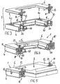
- eine erfindungsgemäße Abdeckung in einer perspektivischen Explosionsdarstellung der Einzelteile,
- Fig. 2
- die Anordnung nach Fig. 1 in Seitenansicht (Pfeilrichtung II),
- Fig. 3
- eine perspektivische Querschnittansicht der wesentlichen Bestandteile vor deren Montage,
- Fig. 4
- eine Ansicht analog zu Fig. 3 im zusammengesetzten, aber noch nicht arretierten Zustand,
- Fig. 5
- eine Darstellung wie in Fig. 4 zusammen mit einem Zentraleinsatz,
- Fig. 6
- eine Ansicht ähnlich Fig. 3, jedoch weitergehend geschnitten,
- Fig. 7
- den zusammengesetzten Zustand ähnlich Fig. 4 mit zusätzlichem Schnitt nach Fig. 6,
- Fig. 8
- einen Diagonalschnitt durch die zusammengesetzte und arretierte Anordnung im Bereich einer Steck-Schraubverbindung,
- Fig. 9
- eine vergrößerte Teilansicht eines als Trägerrahmen ausgebildeten Basisteils mit von einem das eigentliche Abdeckteil bildenden Blendrahmen getrennt dargestellten Bestandteilen,
- Fig. 10
- eine Ansicht ähnlich Fig. 9 aus anderem Blickwinkel,
- Fig. 11
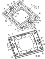
- eine Perspektivansicht auf den gesamten Trägerrahmen (Oberseite) und
- Fig. 12
- eine Perspektivansicht des Trägerrahmens auf dessen Montageseite (Unterseite).
Claims (25)
- Abdeckung (1) für Elektro-Installationsgeräte, wie Schalter, Steckdosen und dergleichen, bestehend aus einem Abdeckteil (6), das über Haltemittel mit einem Basisteil (4) verbindbar ist,
dadurch gekennzeichnet, , dass die Haltemittel von Steck-Rastverbindungen (40) derart gebildet sind, daß zwischen dem Abdeckteil (6) und dem Basisteil (4) eine diese beiden Teile gegeneinander ziehende Vorspannkraft (F) erzeugt wird. - Abdeckung nach Anspruch 1,
dadurch gekennzeichnet, dass das im Wesentlichen mit rechteckiger oder quadratischer Außenkontur ausgebildete Abdeckteil (6) über insbesondere vier in seinen Eckbereichen angeordnete Steck-Rastverbindungen (40) mit dem Basisteil (4) verbindbar ist, wobei jede Steck-Rastverbindung (40) eine Vorspannkraft (F) erzeugt. - Abdeckung nach Anspruch 1 oder 2,
dadurch gekennzeichnet, dass das Basisteil als ein an dem Installationsgerät befestigbarer Trägerrahmen (4) und das Abdeckteil als ein an dem Trägerrahmen (4) diesen überdeckend befestigbarer Blendrahmen (6) ausgebildet sind, wobei Träger- und Blendrahmen (4, 6) gemeinsam zum Abdecken eines einen Zentraleinsatz (2) des Installationsgerätes umschließenden Flächenbereichs dienen. - Abdeckung nach Anspruch 3,
dadurch gekennzeichnet, dass der Blendrahmen (6) an dem Trägerrahmen (4) zusätzlich über Steck-Schraub-Haltemittel (10) derart befestigbar ist, daß eine Montage allein durch einen Steckfügevorgang sowie eine Demontage nur nach einem Schraublösevorgang durchführbar sind. - Abdeckung nach Anspruch 3 oder 4,
gekennzeichnet durch einen sandwichartig zwischen dem Trägerrahmen (4) und dem Blendrahmen (6) anzuordnenden Zwischenrahmen (8). - Abdeckung nach Anspruch 5,
dadurch gekennzeichnet, dass der Zwischenrahmen (8) zur Vormontage insbesondere an dem Blendrahmen (6) fixierbar ist. - Abdeckung nach einem der Ansprüche 3 bis 6,
dadurch gekennzeichnet, dass der Trägerrahmen (4), der Blendrahmen (6) und gegebenenfalls der Zwischenrahmen (8) in ihrem montierten, miteinander verbundenen Zustand im Bereich ihrer äußeren Ränder im wesentlichen deckungsgleich aufeinander liegen. - Abdeckung nach einem der Ansprüche 4 bis 7,
dadurch gekennzeichnet, dass die Steck-Schraub-Haltemittel aus mindestens zwei in diametral gegenüberliegenden Rahmenbereichen, insbesondere jeweils mittig im Bereich von zueinander parallelen Rahmenstegen (12), angeordneten Steck-Schraubverbindungen (10) bestehen. - Abdeckung nach Anspruch 8,
dadurch gekennzeichnet, dass jede Steck-Schraubverbindung (10) aus einem Steckansatz (14) des Blendrahmens (6) und aus einer Steckaufnahme (16) des Trägerrahmens (4) besteht, wobei der in die Steckaufnahme (16) einzusteckende Steckansatz (14) an seinem Ende Spreizarme (18) aufweist, die in eine Erweiterung (20) der Steckaufnahme (16) eingreifen und mittels einer durch den Steckansatz (14) einsteckbaren Schraube (22) spreizbar sind. - Abdeckung nach Anspruch 9,
dadurch gekennzeichnet, dass zwischen dem Blendrahmen (6) und dem Gewinde der eingesteckten Schraube (22), insbesondere im Bereich der gespreizten Spreizarme (18), ein Kraft- und/oder Kraftformschluß derart besteht, daß die Schraube (22) aus ihrer eingesteckten Montageposition durch Herausschrauben in eine die Spreizung der Spreizarme (18) aufhebende Löseposition überführbar ist. - Abdeckung nach einem der Ansprüche 4 bis 10,
dadurch gekennzeichnet, dass die Steck-Schraub-Haltemittel (10) derart ausgebildet sind, daß durch den Steckfügevorgang eine selbsttätige Ausrichtung des Blendrahmens (6) relativ zu dem Trägerrahmen (4) in eine definierte Relativposition erfolgt. - Abdeckung nach einem der Ansprüche 9 bis 11,
dadurch gekennzeichnet, dass die Erweiterung (20) der Steckaufnahme (16) als Innenkonus ausgebildet ist und der Steckansatz (14) endseitig mindestens drei radialsymmetrische Spreizarme (18) aufweist, so daß beim Spreizen eine Selbstzentrierung des Steckansatzes (14) innerhalb der Steckaufnahme (16) und damit eine Selbstausrichtung der Relativposition zwischen Blendrahmen (6) und Trägerrahmen (4) erreicht wird. - Abdeckung nach einem der Ansprüche 4 bis 10,
dadurch gekennzeichnet, dass dieSteck-Schraub-Haltemittel (10) derart ausgebildet sind, daß bei oder nach dem Steckfügevorgang eine manuelle Justierung der Relativposition zwischen Blendrahmen (6) und Trägerrahmen (4) in Richtung wenigstens einer Justierachse (26) durchführbar ist, wobei die Justierachse (26) parallel zu zwei gegenüberliegenden Rahmenstegen (12) verläuft. - Abdeckung nach einem der Ansprüche 9, 10 oder 13,
dadurch gekennzeichnet, , dass die Erweiterung (20) der Steckaufnahme (16) aus zwei gegenüberliegenden, dachartig schrägen Innenflächen besteht und der Steckansatz (16) endseitig zwei entsprechend zur Anlage an den schrägen Innenflächen gegenüberliegende Spreizarme (18) derart aufweist, daß der Steckansatz (14) in der Steckaufnahme (16) in Richtung einer Symmetrieachse der Spreizarme (18) und der schrägen Innenflächen justierbar ist, wobei die Symmetrieachse parallel zu der Justierachse (26) von Blend- und Trägerrahmen (6, 4) verläuft. - Abdeckung nach einem der Ansprüche 9 bis 14,
dadurch gekennzeichnet, dass jeder Steckansatz (14) zumindest kraftschlüssig in die zugehörige Steckaufnahme (16) eingreift. - Abdeckung nach einem der Ansprüche 13 bis 15,
dadurch gekennzeichnet, dass jeder Steckansatz (14) derart in die zugehörige Steckaufnahme (16) eingreift, daß er darin in Richtung einer Einstellachse relativ beweglich ist, wobei die Einstellachse parallel zu der Justierachse (26) von Blend- und Trägerrahmen (6, 4) verläuft. - Abdeckung nach einem der Ansprüche 13 bis 16,
dadurch gekennzeichnet, dass jeder Steckansatz (14) im Wesentlichen hohlzylindrisch mit einem Außendurchmesser ausgebildet ist, der kleiner als der Innendurchmesser der bevorzugt ebenfalls hohlzylindrischen Steckaufnahme (16) ist, wobei der Steckansatz (14) auf seinem Außenumfang mindestens zwei längliche und in Steckrichtung verlaufende sich vom Steckansatz (14) weg radial in entgegengesetzte Richtungen und senkrecht zur Justierachse (26) bzw. zur Einstellachse erstreckende Anlagerippen (28) zur kraftschlüssigen Anlage in der Steckaufnahme (16) aufweist. - Abdeckung nach einem der Ansprüche 13 bis 17,
dadurch gekennzeichnet, , dass jeder Steckansatz (14) auf seinem Außenumfang zwei längliche und in Steckrichtung verlaufende, sich vom Steckansatz (14) weg radial in entgegengesetzte Richtungen und parallel zur Justierachse (26) bzw. zur Einstellachse erstreckende Einsteckrippen (30) zum kraftschlüssigen Einstecken in korrespondierende Aufnahmeschlitze (32) der Steckaufnahme (16) aufweist. - Abdeckung nach einem der Ansprüche 1 bis 18,
dadurch gekennzeichnet, dass jede Steck-Rastverbindung (40) derart ausgebildet ist, daß sie eine manuelle Justierung zwischen Blendrahmen (6) und Trägerrahmen (4) in Richtung einer Justierachse (26) ermöglicht. - Abdeckung nach einem der Ansprüche 1 bis 19,
dadurch gekennzeichnet, dass jede Steck-Rastverbindung (40) einerseits aus zwei federelastischen Rastarmen (42) und andererseits aus einem zwischen die Rastarme (42) einsteckbaren Steckeransatz (44) besteht, wobei die Rastarme (42) mit dem Steckeransatz (44) über Schrägflächen derart zusammenwirken, daß durch ihre Federetastizität über die Schrägflächen die die Rahmenteile (4, 6) zusammenziehende Vorspannkraft (F) erzeugt wird. - Abdeckung nach Anspruch 20,
dadurch gekennzeichnet, dass der Steckeransatz (44) nach Art eines Flachsteckers ausgebildet und in seinem zwischen die Rastarme (42) eingesteckten Zustand relativ zu diesem in Richtung einer Querachse beweglich ist, wobei die Querachse parallel zu der Justierachse (26) verläuft. - Abdeckung nach einem der Ansprüche 3 bis 21,
dadurch gekennzeichnet, dass der Trägerrahmen (4) in von dem Blendrahmen (6) überdeckten Bereichen Schraubenlöcher (50) zur zusätzlichen Schraubbefestigung im jeweils neben dem Installationsgerät liegenden Bereich einer Montagefläche aufweist. - Abdeckung nach Anspruch 22,
dadurch gekennzeichnet, dass jedes Schraubenloch (50) als Langlochöffnung ausgebildet ist. - Abdeckung insbesondere nach Anspruch 23,
dadurch gekennzeichnet, dass im Bereich jeder Langlochöffnung (50) ein verdünnter, herausbrechbarer Wandungsabschnitt (54) angeordnet ist, wobei dieser Wandungsabschnitt (54) ein bezogen auf die Langlochöffnung (50) zentrisches, kreisförmiges Anreißloch (56) aufweist. - Abdeckung nach Anspruch 23 oder 24,
dadurch gekennzeichnet, dass jedeLanglochöffnung(50) durch zwei konzentrische, gegeneinander winkelversetzte Langlöcher gebildet ist.
Applications Claiming Priority (2)
| Application Number | Priority Date | Filing Date | Title |
|---|---|---|---|
| DE20011553U | 2000-07-01 | ||
| DE20011553U DE20011553U1 (de) | 2000-07-01 | 2000-07-01 | Abdeckung für Elektro-Installationsgeräte insbesondere in Unterputz-Ausführung |
Publications (3)
| Publication Number | Publication Date |
|---|---|
| EP1168557A2 EP1168557A2 (de) | 2002-01-02 |
| EP1168557A3 EP1168557A3 (de) | 2003-04-02 |
| EP1168557B1 true EP1168557B1 (de) | 2004-08-18 |
Family
ID=7943483
Family Applications (1)
| Application Number | Title | Priority Date | Filing Date |
|---|---|---|---|
| EP01114521A Expired - Lifetime EP1168557B1 (de) | 2000-07-01 | 2001-06-16 | Abdeckung für Elektro-Installationsgeräte insbesondere in Unterputz-Ausführung |
Country Status (3)
| Country | Link |
|---|---|
| EP (1) | EP1168557B1 (de) |
| AT (1) | ATE274248T1 (de) |
| DE (2) | DE20011553U1 (de) |
Cited By (1)
| Publication number | Priority date | Publication date | Assignee | Title |
|---|---|---|---|---|
| DE202012101349U1 (de) | 2012-04-13 | 2012-05-08 | Rehau Ag + Co | Steckdosen-Anordnung für Geräteeinbaukanäle mit einer Halteschiene am Kanalbo-den sowie Geräteeinbaukanal, der eine derartige Steckdosen-Anordnung umfasst |
Family Cites Families (9)
| Publication number | Priority date | Publication date | Assignee | Title |
|---|---|---|---|---|
| FR1457719A (fr) * | 1965-09-21 | 1966-11-04 | Système de fixation sur boîtier d'une plaque de recouvrement de petit appareillageélectrique | |
| DE1908480C3 (de) * | 1969-02-20 | 1979-04-05 | Siemens Ag, 1000 Berlin Und 8000 Muenchen | Bodendose für elektrische Unterflur-Installationen mit einem Rahmen, der einen Deckel aufnimmt |
| DE2632326C3 (de) * | 1976-07-17 | 1980-04-24 | Neuwalzwerk Bettermann Ohg, 5750 Menden | Unter Flur anzuordnender Kabelkanal-Anschlußkasten |
| DE7627228U1 (de) * | 1976-08-31 | 1976-12-30 | Neuwalzwerk Bettermann Ohg, 5759 Boesperde | Unter Flur anzuordnender Kabelkanal-AnschluBkasten |
| DE8707084U1 (de) * | 1987-05-16 | 1987-12-10 | Striebel & John Kg, 7591 Sasbach | Verschluß zur lösbaren Befestigung einer Abdeckung auf einer Unterlage, insbesondere für den Einsatz an elektrischen Verteilerkästen, Schaltschränken o. dgl. Einrichtungen |
| DE8907772U1 (de) * | 1989-06-24 | 1989-10-26 | Fenzl Jun., Maximilian | Bodendose |
| FR2719091B1 (fr) * | 1994-04-25 | 1996-05-24 | Merlin Gerin | Cheville de fixation murale et écrou associé. |
| JPH0898366A (ja) * | 1994-09-27 | 1996-04-12 | Matsushita Electric Works Ltd | 配線器具の表面プレートの構造 |
| EP0961374B1 (de) * | 1998-03-27 | 2000-09-27 | Bertoldo & C. Srl | Gehäuse für elektrische Geräte mit abnehmbarem Deckel und Deckelbefestigungsanordnung |
-
2000
- 2000-07-01 DE DE20011553U patent/DE20011553U1/de not_active Expired - Lifetime
-
2001
- 2001-06-16 EP EP01114521A patent/EP1168557B1/de not_active Expired - Lifetime
- 2001-06-16 AT AT01114521T patent/ATE274248T1/de active
- 2001-06-16 DE DE50103283T patent/DE50103283D1/de not_active Expired - Lifetime
Cited By (2)
| Publication number | Priority date | Publication date | Assignee | Title |
|---|---|---|---|---|
| DE202012101349U1 (de) | 2012-04-13 | 2012-05-08 | Rehau Ag + Co | Steckdosen-Anordnung für Geräteeinbaukanäle mit einer Halteschiene am Kanalbo-den sowie Geräteeinbaukanal, der eine derartige Steckdosen-Anordnung umfasst |
| EP2650994A2 (de) | 2012-04-13 | 2013-10-16 | REHAU AG + Co | Steckdosen-Anordnung für Geräteeinbaukanäle mit einer Halteschiene am Kanalboden sowie Geräteeinbaukanal, der eine derartige Steckdosen-Anordnung umfasst |
Also Published As
| Publication number | Publication date |
|---|---|
| EP1168557A3 (de) | 2003-04-02 |
| ATE274248T1 (de) | 2004-09-15 |
| EP1168557A2 (de) | 2002-01-02 |
| DE50103283D1 (de) | 2004-09-23 |
| DE20011553U1 (de) | 2001-11-15 |
Similar Documents
| Publication | Publication Date | Title |
|---|---|---|
| DE3736319C2 (de) | ||
| DE3211511C2 (de) | Zugentlastung bewirkende Kabeldurchführung | |
| DE102015101829A1 (de) | Spannklaue zur Anbringung an einer Gleitschiene eines Operationstisches | |
| EP1834871B1 (de) | Anordnung zur lösbaren Befestigung von Bauteilen an einer Decke oder Wand | |
| DE4428496C2 (de) | Kugelgelenk | |
| DE3705413C2 (de) | ||
| DE29520459U1 (de) | Elektrisches Installationsgerät mit Zentralabdeckung | |
| EP1168556B9 (de) | Rahmen-Anordnung für Elektro-Installationsgeräte insbesondere in Unterputz-Ausführung | |
| DE19527778C2 (de) | Kabelstecker für ein Fahrzeug | |
| WO2021089462A1 (de) | Steckverbinderteil mit einer rasteinrichtung | |
| EP0899504A2 (de) | Leuchtengehäuse | |
| EP3093937B1 (de) | Sockelteil für elektrische installationsgeräte | |
| EP1168557A2 (de) | Abdeckung für Elektro-Installationsgeräte insbesondere in Unterputz-Ausführung | |
| DE4030765A1 (de) | Armatur | |
| DE19725401C1 (de) | Bohrvorrichtung mit Begrenzung des Bohrweges | |
| EP2690728B1 (de) | Hohlwanddose zur Elektro-Installation | |
| EP3282178B1 (de) | Steckverbindung für einen lampenkörper | |
| DE4416268A1 (de) | Vorrichtung zum Ein- bzw. Ausdrehen von Innensechskant-Schrauben | |
| DE3605209C2 (de) | ||
| EP3601883B1 (de) | Leuchte mit verstellbarem lichtkopf | |
| EP0728952B1 (de) | Klemmverbindung, insbesondere zur Festlegung von Gehäuseteilen elektrischer Geräte, und Verschlusselement dafür | |
| DE4341277C1 (de) | Elektrisches Installationsgerät | |
| DE8424990U1 (de) | Näherungsschalter | |
| DE102009048554B4 (de) | Steckführungseinrichtung zur Verbindung mit einer Steckerleiste | |
| DE2717354C3 (de) | Verriegelung für Gehäuseteile eines elektrischen Installationsgerätes |
Legal Events
| Date | Code | Title | Description |
|---|---|---|---|
| PUAI | Public reference made under article 153(3) epc to a published international application that has entered the european phase |
Free format text: ORIGINAL CODE: 0009012 |
|
| AK | Designated contracting states |
Kind code of ref document: A2 Designated state(s): AT BE CH CY DE DK ES FI FR GB GR IE IT LI LU MC NL PT SE TR |
|
| AX | Request for extension of the european patent |
Free format text: AL;LT;LV;MK;RO;SI |
|
| PUAL | Search report despatched |
Free format text: ORIGINAL CODE: 0009013 |
|
| AK | Designated contracting states |
Kind code of ref document: A3 Designated state(s): AT BE CH CY DE DK ES FI FR GB GR IE IT LI LU MC NL PT SE TR |
|
| AX | Request for extension of the european patent |
Extension state: AL LT LV MK RO SI |
|
| 17P | Request for examination filed |
Effective date: 20030913 |
|
| GRAP | Despatch of communication of intention to grant a patent |
Free format text: ORIGINAL CODE: EPIDOSNIGR1 |
|
| AKX | Designation fees paid |
Designated state(s): AT DE NL |
|
| GRAS | Grant fee paid |
Free format text: ORIGINAL CODE: EPIDOSNIGR3 |
|
| GRAA | (expected) grant |
Free format text: ORIGINAL CODE: 0009210 |
|
| AK | Designated contracting states |
Kind code of ref document: B1 Designated state(s): AT DE NL |
|
| REG | Reference to a national code |
Ref country code: IE Ref legal event code: FG4D Free format text: GERMAN |
|
| REF | Corresponds to: |
Ref document number: 50103283 Country of ref document: DE Date of ref document: 20040923 Kind code of ref document: P |
|
| REG | Reference to a national code |
Ref country code: IE Ref legal event code: FD4D |
|
| PLBE | No opposition filed within time limit |
Free format text: ORIGINAL CODE: 0009261 |
|
| STAA | Information on the status of an ep patent application or granted ep patent |
Free format text: STATUS: NO OPPOSITION FILED WITHIN TIME LIMIT |
|
| 26N | No opposition filed |
Effective date: 20050519 |
|
| PGFP | Annual fee paid to national office [announced via postgrant information from national office to epo] |
Ref country code: NL Payment date: 20180626 Year of fee payment: 18 |
|
| PGFP | Annual fee paid to national office [announced via postgrant information from national office to epo] |
Ref country code: AT Payment date: 20180710 Year of fee payment: 18 |
|
| REG | Reference to a national code |
Ref country code: NL Ref legal event code: MM Effective date: 20190701 |
|
| REG | Reference to a national code |
Ref country code: AT Ref legal event code: MM01 Ref document number: 274248 Country of ref document: AT Kind code of ref document: T Effective date: 20190616 |
|
| PG25 | Lapsed in a contracting state [announced via postgrant information from national office to epo] |
Ref country code: AT Free format text: LAPSE BECAUSE OF NON-PAYMENT OF DUE FEES Effective date: 20190616 Ref country code: NL Free format text: LAPSE BECAUSE OF NON-PAYMENT OF DUE FEES Effective date: 20190701 |
|
| PGFP | Annual fee paid to national office [announced via postgrant information from national office to epo] |
Ref country code: DE Payment date: 20200828 Year of fee payment: 20 |
|
| REG | Reference to a national code |
Ref country code: DE Ref legal event code: R071 Ref document number: 50103283 Country of ref document: DE |