EP1168019A2 - Stecker mit Verbindungs-Detektierungsfunktion, faseroptisches Kabel mit dieser Funktion sowie Gerätesatz-Schaltvorrichtung für einen optischen Gerätesatz - Google Patents
Stecker mit Verbindungs-Detektierungsfunktion, faseroptisches Kabel mit dieser Funktion sowie Gerätesatz-Schaltvorrichtung für einen optischen Gerätesatz Download PDFInfo
- Publication number
- EP1168019A2 EP1168019A2 EP01114701A EP01114701A EP1168019A2 EP 1168019 A2 EP1168019 A2 EP 1168019A2 EP 01114701 A EP01114701 A EP 01114701A EP 01114701 A EP01114701 A EP 01114701A EP 1168019 A2 EP1168019 A2 EP 1168019A2
- Authority
- EP
- European Patent Office
- Prior art keywords
- connector
- electric wiring
- loop
- optical fiber
- conducting state
- Prior art date
- Legal status (The legal status is an assumption and is not a legal conclusion. Google has not performed a legal analysis and makes no representation as to the accuracy of the status listed.)
- Withdrawn
Links
- 230000003287 optical effect Effects 0.000 title claims abstract description 155
- 239000013307 optical fiber Substances 0.000 title claims description 110
- 238000001514 detection method Methods 0.000 title claims description 82
- 239000004020 conductor Substances 0.000 claims description 67
- 238000012790 confirmation Methods 0.000 claims description 18
- 238000010276 construction Methods 0.000 description 18
- 238000004891 communication Methods 0.000 description 5
- 230000003014 reinforcing effect Effects 0.000 description 5
- 230000005611 electricity Effects 0.000 description 4
- 230000002093 peripheral effect Effects 0.000 description 4
- 230000002411 adverse Effects 0.000 description 3
- 230000006835 compression Effects 0.000 description 2
- 238000007906 compression Methods 0.000 description 2
- 206010016275 Fear Diseases 0.000 description 1
- 238000006073 displacement reaction Methods 0.000 description 1
- 230000000694 effects Effects 0.000 description 1
- 230000006698 induction Effects 0.000 description 1
- 238000003754 machining Methods 0.000 description 1
- 239000002184 metal Substances 0.000 description 1
- 238000000034 method Methods 0.000 description 1
- 238000012986 modification Methods 0.000 description 1
- 230000004048 modification Effects 0.000 description 1
- 230000035945 sensitivity Effects 0.000 description 1
- 238000010792 warming Methods 0.000 description 1
- 238000003466 welding Methods 0.000 description 1
Images


Classifications
-
- G—PHYSICS
- G02—OPTICS
- G02B—OPTICAL ELEMENTS, SYSTEMS OR APPARATUS
- G02B6/00—Light guides; Structural details of arrangements comprising light guides and other optical elements, e.g. couplings
- G02B6/24—Coupling light guides
- G02B6/36—Mechanical coupling means
- G02B6/38—Mechanical coupling means having fibre to fibre mating means
- G02B6/3807—Dismountable connectors, i.e. comprising plugs
- G02B6/389—Dismountable connectors, i.e. comprising plugs characterised by the method of fastening connecting plugs and sockets, e.g. screw- or nut-lock, snap-in, bayonet type
-
- G—PHYSICS
- G02—OPTICS
- G02B—OPTICAL ELEMENTS, SYSTEMS OR APPARATUS
- G02B6/00—Light guides; Structural details of arrangements comprising light guides and other optical elements, e.g. couplings
- G02B6/24—Coupling light guides
- G02B6/42—Coupling light guides with opto-electronic elements
- G02B6/4296—Coupling light guides with opto-electronic elements coupling with sources of high radiant energy, e.g. high power lasers, high temperature light sources
- G02B2006/4297—Coupling light guides with opto-electronic elements coupling with sources of high radiant energy, e.g. high power lasers, high temperature light sources having protection means, e.g. protecting humans against accidental exposure to harmful laser radiation
-
- G—PHYSICS
- G02—OPTICS
- G02B—OPTICAL ELEMENTS, SYSTEMS OR APPARATUS
- G02B6/00—Light guides; Structural details of arrangements comprising light guides and other optical elements, e.g. couplings
- G02B6/24—Coupling light guides
- G02B6/36—Mechanical coupling means
- G02B6/38—Mechanical coupling means having fibre to fibre mating means
- G02B6/3807—Dismountable connectors, i.e. comprising plugs
- G02B6/381—Dismountable connectors, i.e. comprising plugs of the ferrule type, e.g. fibre ends embedded in ferrules, connecting a pair of fibres
- G02B6/3818—Dismountable connectors, i.e. comprising plugs of the ferrule type, e.g. fibre ends embedded in ferrules, connecting a pair of fibres of a low-reflection-loss type
- G02B6/3821—Dismountable connectors, i.e. comprising plugs of the ferrule type, e.g. fibre ends embedded in ferrules, connecting a pair of fibres of a low-reflection-loss type with axial spring biasing or loading means
-
- G—PHYSICS
- G02—OPTICS
- G02B—OPTICAL ELEMENTS, SYSTEMS OR APPARATUS
- G02B6/00—Light guides; Structural details of arrangements comprising light guides and other optical elements, e.g. couplings
- G02B6/24—Coupling light guides
- G02B6/36—Mechanical coupling means
- G02B6/38—Mechanical coupling means having fibre to fibre mating means
- G02B6/3807—Dismountable connectors, i.e. comprising plugs
- G02B6/389—Dismountable connectors, i.e. comprising plugs characterised by the method of fastening connecting plugs and sockets, e.g. screw- or nut-lock, snap-in, bayonet type
- G02B6/3894—Screw-lock type
Definitions
- This invention relates to a connector and an optical fiber cable each having a function by which when a connector provided at a cable end is improperly connected to a receptacle, this connected condition can be detected.
- This invention also relates to an equipment control mechanism for an optical equipment connected to a connector, by which when the connector provided at a cable end is improperly connected to a receptacle, the operating condition of the equipment is controlled in accordance with this detection result.
- optical fibers have been used in many fields.
- the use of optical fibers as communication media has become the mainstream of optical communication.
- laser beam machines have been extensively used for cutting, welding and so on, and an optical fiber has been used as means for transferring this laser beam.
- an optical receptacle for connecting a light source or an equipment, such as an optical transceiver and an optical measuring instrument, to an optical fiber
- an optical receptacle for connecting a light source or an equipment, such as an optical transceiver and an optical measuring instrument, to an optical fiber
- an optical receptacle for connecting a light source or an equipment, such as an optical transceiver and an optical measuring instrument, to an optical fiber
- an optical receptacle provided at an optical input/output portion of the equipment, is coupled and connected to an optical connector provided at an end of the optical fiber.
- an optical receptacle provided at a laser beam source or an emitting optical system or the like for radiating a laser beam toward an object to be machined, is coupled and connected to an optical connector provided at an end of an optical fiber.
- connection detection mechanism capable of detecting the secure connection between an optical connector and an optical receptacle.
- Fig. 16 shows the construction of a connector connection detection mechanism disclosed in Japanese Patent Unexamined Publication No. Hei. 9-9016S.
- a laser diode 2 for emitting a laser beam is provided within a laser oscillator 1.
- An optical receptacle 3 is mounted on a panel of the laser oscillator 1, and is coupled to the laser diode 2 by an optical fiber 4.
- Fig. 17 is a cross-sectional view of the above connector connection detection mechanism.
- the optical receptacle 3 is fixedly secured to the panel 1a of the laser oscillator 1 through a flange 3a formed on this optical receptacle 3.
- a sleeve 3c is formed on an optical connector-connecting side of the optical receptacle 3, and a ferrule 5 is held in the sleeve 3c, so as to move in a direction of the axis of the optical receptacle 3.
- the optical fiber 4 is connected to a laser oscillator-side end of the ferrule 5, and a proximity switch 6 is provided at an end of the optical fiber 4 through an arm 6a.
- a sensing member 3b is provided at a laser oscillator-side end of the optical receptacle 3, and when the proximity switch 6 is brought into contact with the sensing member 3b, this proximity switch is turned into a conducting state.
- the ferrule 5 is normally urged toward a distal end of the sleeve 3c by a compression coil spring (urging means) 7, and is kept stationary in a position where the proximity switch 6 contacts the sensing member 3b.
- the laser diode 2 can emit a laser beam under the control of a control circuit (not shown).
- the switch is unable to emit a laser beam. Therefore, as long as the optical connector is not connected to the optical receptacle, the laser beam can be prevented from being accidentally emitted.
- This invention seeks to solve the above problems, and it is an object of the invention to provide a connector with a connection detection function and an optical cable with a connection detection function, which enables a connector connection detection mechanism to be easily provided on already-installed optical equipments. It is another object of the invention to provide an equipment control mechanism for an optical equipment.
- a connector with a connection detection function the connector being adapted to be connected to a fixed receptacle and comprising:
- the longitudinally extending member comprises a cable.
- the longitudinally extending member comprises a optical fiber cable.
- the switch is electrically insulated from the fixed receptacle when the connector comes into contact with the fixed receptacle.
- the switch is changed from the electrical non-conducting state to the electrical conducting state only when the connector is properly fitted to the fixed receptacle.
- the switch may be changed from the electrical conducting state to an electrical non-conducting state only when the connector is properly fitted to the fixed receptacle.
- the switch comprises:
- the conductor piece may be a coil spring.
- the switch comprises a proximity switch.
- the proximity switch means a device, the conducting state of which is switched when the distal end of the device comes into contact with some object, or when the device reacts to the proximity of an actuating means without physical contact therewith.
- known proximity switches such as a high-frequency induction proximity switch (which operates in response to a change in the magnetic field) and an electrical capacitance-type proximity switch, can be used as the proximity switch.
- connection detection function is provided not at the fixed receptacle but at the portable connector. Therefore the connector connection detection function can be added, using a receptacle provided at an existing equipment not provided with a detection function.
- an optical fiber cable with a connection detection function comprising:
- the above-mentioned optical fiber cable may further comprises: a conduction confirmation member for confirming the conducting and non-conducting states of the loop-shapedelectric wiring.
- examples of the conduction confirmation member include a light emitting device which becomes luminous, and a device which produces a sound, in the conducting state of the electric wiring.
- optical fiber cable may further comprises: an outputting member for outputting information regarding the conducting and non-conducting states of the loop-shaped electric wiring.
- the outputting member is, for example, a device which measures a current and a voltage, and detects a resistance value in the electric wiring.
- an optical fiber cable with a connection detection function comprising:
- the above-mentioned optical fiber cable may further comprises: a conduction confirmation member for confirming the conducting and non-conducting states of the loop-shaped electric wiring.
- optical fiber cable may further comprises: an outputting member for outputting information regarding the conducting and non-conducting states of the loop-shaped electric wiring.
- an optical fiber cable with a connection detection function comprising:
- an outputting member is provided at the first electric wiring for outputting information regarding the conducting and non-conducting states of the second and third electric wirings.
- the second electric wiring and the third electric wiring are different in resistance value from each other.
- an optical fiber cable with a connection detection function comprising:
- optical fiber cable it is preferable to further comprises: an outputting member, provided at the first electric wiring, for outputting information regarding the conducting and non-conducting states of the second and third electric wirings.
- the second electric wiring and the third electric wiring are different in resistance value from each other.
- connection detection function is not fixedly provided at an equipment, but is provided at the optical fiber cable releasably connectable to this equipment. Therefore, the connector connection detection function can be added, using the existing equipment not provided with a detection function.
- the resistance value of the second electric wiring is different from that of the third electric wiring, and therefore whether or not the connectors, provided respectively at the opposite ends, have been properly connected, is outputted as the conducting and non-conducting information from the outputting member. Namely, when the distance between the outputting member and the connector operatively connected to the second electric wiring, is equal to the distance between the outputting member and the connector operatively connected to the third electric wiring, and the resistance values of the second and third electric wirings are different from each other, then it can be confirmed from the conducting and non-conducting information (resistance value), outputted from the outputting member, which of connectors is incompletely connected.
- the second and third electric wirings are respectively provided with different resistances, if the values of the resistances are large enough to ignore the resistance values of the electric wirings, it can be confirmed without depending on the resistance value or length of the electric wiring, from the conducting and non-conducting information (resistance value), outputted from the outputting member, which of connectors is incompletely connected.
- an equipment control mechanism for an optical equipment comprising:
- the optical equipment is a laser oscillator, and when an incompletely-connected condition of the connector is detected from the conducing and non-conducting information outputted from the outputting member, the laser oscillator is prevented from emitting a laser beam.
- the optical equipment is a laser oscillator, and when an incompletely-connected condition of the connector is detected from the conducing and non-conducting information outputted from the outputting member, the operation of the laser oscillator is stopped.
- the connected condition of the connector provided at the end of the optical fiber cable to the equipment can be detected, and the operation of the equipment, to which the optical fiber cable is connected, can be controlled on the basis of the detection results.
- Fig. 1 shows a connector with a connection detection function according to a first embodiment of the invention.
- Reference numeral 10 denotes an optical connector with the connection detection function used for a laser beam-transferring optical fiber.
- Reference numeral 11 denotes an optical receptacle provided at an equipment, that is, a laser oscillator.
- An optical fiber 13 is inserted in a ferrule 12 along an axis thereof, and an end portion of this optical fiber 13 is haldbythis ferrule.
- Anut 14 serves to fix the optical connector 10 to the optical receptacle 11.
- a nut retaining member 15 is fixedly mounted on the outer periphery of the ferrule 12. The nut 14 is held on the nut retaining member 15, so as to move in a direction of the axis of the optical connector 10 and also to rotate about this axis.
- Slide pins 16a and 16b are held in a gap between the ferrule 12 and the nut retaining member 15 so as to move in the direction of the axis of the optical connector 10.
- a sensing member 17 of an annular shape is mounted around the outer periphery of the ferrule 12. The sensing member 17 is fixedly secured to proximal ends of the slide pins 16a and 16b, and is movable in the direction of the axis of the optical connector 10 together with these slide pins 16a and 16b.
- the slide pins 16a and 16b and the sensing member 17 jointly form a moving member 18 of the invention.
- Reference numeral 19 denotes a coil spring, reference numeral 20 a spring retaining member of an annular shape, and reference numeral 21 a proximity switch mounted on a distal end of the spring retaining member 20.
- the proximity switch 21 is switched from the non-conducting state to the conducting state (for example, through the movement of its internal components and so on) when a distal end of the proximity switch comes into contact with some object.
- the spring retaining member 20 is fixedly secured to the ferrule 12 in such a manner that when the moving member 18 abuts against the proximal end surface 15b of the nut retaining member 15, the sensing member 17 is spaced the above predetermined distance X from the proximity switch 21.
- the coil spring 19 is wound on the outer peripheral surface of the ferrule 12 between the sensing member 17 and the spring retaining member 20. This coil spring 19 is held by the spring retaining member 20 such that this coil spring 19 normally urges the sensing member 17 toward the distal end of the optical connector 10 to space the sensing member 17 apart from the proximity switch 21. In the above construction, the coil spring 19 may not normally urge the sensing member 17 toward the distal end of the optical connector 10 in so far as the sensing member 17 and the proximity switch 21 are normally spaced apart from each other.
- Fig. 2 shows a condition in which the optical connector 10 is properly connected to the optical receptacle 11.
- the distal ends of the slide pins 16a and 16b abut against a distal end surface lie of the optical receptacle 11, so that the sensing member 17 is moved toward the proximity switch 21.
- the sensing member 17 comes into contact with the proximity switch 21, so that this proximity switch 21 is turned into the conducting state.
- a lamp (not shown), associated with this switch, is lighted, and therefore the fact that the optical connector 10 has been properly connected to the optical receptacle 11 can be detected.
- the nut 14 is securely tightened relative to the optical receptacle 11, and by doing so, the displacement and withdrawal of the optical connector are prevented, so that the properly-connected condition can be maintained.
- Figs. 3 and 4 show a condition in which the optical connector 10 is not properly connected to the optical receptacle 11.
- Fig. 3 shows a condition in which the nut 14 is not sufficiently tightened relative to the optical receptacle 11.
- a force acts on the ferrule 12 to withdraw the same from the optical receptacle 11 in a direction indicated by an arrow (Fig. 3)
- a gap is formed between the distal end surface 11e of the optical receptacle 11 and the distal end surface 15f of the nut retaining member 15 by this pulling force.
- a gap is formed between the sensing member 17 urged toward the nut retaining member 15 by the coil spring 19, and the proximity switch 21, so that the sensing member 17 and the proximity switch 21 are out of contact with each other.
- Fig. 4 shows a condition in which the optical connector 10 is not fitted straight relative to a central axis 22 of the optical receptacle 11, and the nut 14 is caught by a threaded portion 11n of the optical receptacle 11.
- the nut 14 fails to be fully tightened relative to the optical receptacle 11, and therefore is disposed short of the fully-tightened position.
- a gap is formed between the distal end surface lie of the optical receptacle 11 and the distal end surface 15f of the nut retaining member 15 as described above, and as a result the sensing member 17 and the proximity switch 21 are disposed out of contact with each other.
- the proximity switch is not turned into the conducting state, and therefore the lamp, associated with this switch, is not lighted.
- the fact that the connection of the optical connector 10 to the optical receptacle 11 is insufficient can be detected.
- the optical connector with the connection detection function of this embodiment is merely one example, and can be designed in accordance with various configurations of optical receptacles.
- the lamp is used as means for confirming the conducting state or the non-conducting state, a warming sound or a display, etc., which can confirm the conducting state or non-conducting state, ca be used.
- the above embodiment is directed to the optical connector for use with the optical fiber cable containing the laser beam-transferring optical fiber, the connector with the connection detection function of the invention can be used for a metal cable.
- Fig. 5 shows a connector with connection detection function according to a second embodiment of the present invention.
- the connector 10 with the connection detection function shown in Figs. 1 to 4 is similar to that of the connector 10 with the connection detection function shown in Figs. 1 to 4, and the same parts as the above-mentioned embodiment are given the same designations and thus the description thereof is omitted.
- the two proximity switches are provided, and only when both of the proximity switches are turned into the conducting state, a lamp (not shown), associated with these switches, is lighted, and therefore the fact that the optical connector 10 has been properly connected to the optical receptacle 11 can be detected.
- a sensing member 17 and the spring retaining member 20 provided with the proximity switches 21a and 21b are contacted with each other without substantial inclination and in a balanced manner.
- the two proximity switches are provided, three or more proximity switches may be provided, so that there can be detected whether or not the sensing member and the proximity switches are connected each other without substantially inclination and in a balanced manner with respect to the axial of the connector 10 as a center in a plurality of directions.
- Figs. 6A and 6B show a connector with a connection detection function according to a third embodiment of the present invention.
- This embodiment differs from the above emodiment in that a switch is formed by a sensing member 67a forming a moving member 68 and a contact portion 61 (a positive-electrode conductor contact 61a and a negative-electrode conductor contact 61b).
- Fig. 6A shows a cross-sectional view of the connector 60a with connection detection function.
- the sensing member 67a is composed of a conductor, that is, is conductor piece.
- the positive-electrode conductor contact 61a and the negative-electrode conductor contact 61b are provided on that end of the spring retaining member 20 opposed to the sensing member 67a.
- a power source (not shown) is connected to these conductor contacts 61a and 61b.
- the contact portion 61 and the spring retaining member 20 are electrically insulated.
- the distal end portions of the slide pins 16a and 16b project a predetermined distance X from a distal end surface 15f of a nut retaining member 15, so that the sensing member 67a can come into contact with both of the positive-electrode conductor contact 61a and the negative-electrode conductor contact 61b when the connector 60a and the receptacle 11 are fitted with each other, and then are brought intro an allowable range of the properly-connected condition.
- Fig. 6B is a plan view of the sensing member 67a as seen from a direction F, and also is a plan view of the contact portion 61 as seen from a direction R.
- the surface of the sensing member 67a is formed by a conductive member.
- the contact portion 61 comprises the positive-electrode conductor contact 61a and the negative-electrode conductor contact 61b disposed respectively at diametrically-opposite portions of the end surface of the annular spring retaining member 20.
- FIGs. 7A and 73 show a connector 60b with s connection detection function having a modified form of the above sensing member.
- a sensing member 67b shown in Fig. 7B which is a plan view as seen from a direction F of Fig. 7A, comprises an insulating portion 670b formed of an insulating member of an annular shape, and an electrically-conductive member (conductor piece) 671b which is provided at part of a surface of this insulating member.
- the electrically-conductive member 671b in the form of a conductor piece, is provided on an outer peripheral portion of the sensing member 67b, disposed radially outwardly of a generally radially-central portion thereof, over an entire circumference thereof.
- This electrically-conductive member 671b is provided on that surface of the sensing member 67b facing a contact portion 61 mounted on a spring retaining member 20.
- a coil spring 19 can come into contact with only the insulating portion 670b of the sensing member 67b.
- the spring retaining member 20 and the contact portion 61 provided at the spring retaining member 20 are electrically insulated to each other. Therefore, the switch of the connector is satisfactorily electrically insulated from the other members of the connector (the spring retaining member 20, the coil spring 19, the sleeve 12, etc.). Namely, when the switch is turned into the conducting state, electricity is prevented from flowing to an optical receptacle 11, thereby preventing an optical equipment, connected to the optical receptacle 11, from being adversely affected.
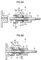
- Figs. 8A and 8B show a connector 80 with a connection detection function according to a fourth embodiment of the present invention. This embodiment differs from the above embodiments in a sensing member 87 forming a moving member 88 and a contact portion 61.
- the annular sensingmember 87 comprises a coaxially-arranged coil spring (conductor piece) 87a, which comprises an annular conductor and is mounted on that surface of the sensing member 87 opposed to a spring retaining member 20.
- the coil spring 87a is provided not to contact with the coil spring 19 and a sleeve 12.
- Apositive-electrode conductor contact 61a and a negative-electrode conductor contact 61b, each comprising a conductor, are mounted on that end of the spring retaining member 20 opposed to the sensing member 87.
- a power source (not shown) is connected to these conductor contacts 61a and 61b.
- the distal end portions of the slide pins 16a and 16b project a predetermined distance X' from a distal end surface 15f of a nut retaining member 15, so that the coil spring 87a can come into contact with both of the positive-electrode conductor contact 61a and the negative-electrode conductor contact 61b when the connector 80 and the receptacle 11 are fitted with each other, and then are brought intro an allowable range of the properly-connected condition.
- Fig. 8B is a plan view of the sensing member 87 as seen from a direction F, and also is a plan view of the contact portion 61 as seen from a direction R.
- the coaxially-arranged coil spring 87a comprising the annular conductor, is mounted on the surface of the annular sensing member 87.
- the contact portion 61 mounted on the end surface of the spring retaining member 20 comprises the positive-electrode conductor contact 61a and the negative-electrode conductor contact 61b disposed respectively at diametrically-opposite portions of the annular spring retaining member 20.
- Fig. 8C is a plan view of the sensing member 87 as seen from a direction F, and also is a plan view of a modified contact portion 61 (different from the contact portion 61 of Fig. 8B), as seen from a direction R.
- the contact portion 61 mounted on the end surface of the spring retaining member 20, comprises positive-electrode conductor contacts 61a and negative-electrode conductor contacts 61b which are arranged alternately on the end surface of the annular spring retaining member 20 in the circumferential direction.
- the conductive portion of the sensing member 87 is formed by the coil spring 87a, and the coil has play width in a compression direction in its natural state. Therefore, even when the contact portion 61 and the sensing member 87 are not disposed in parallel relation to each other with high accuracy, the play width of the coil spring 87a compensates for this deviation. Thus when the switch is operated, the good conducting state thereof can be secured.
- the plurality of positive-electrode conductor contacts 61a and the plurality of negative-electrode conductor contacts 61b are arranged alternately, and therefore the sensitivity of the switch is enhanced.
- the sensing member 87 may be formed by the insulating member, so that the contact portion 61 and coil spring 87 a are electrically insulated from the other members of the connector. Therefore the switch of the connector is satisfactorily electrically insulated from the other members of the connector even if the switch is tuned into the conducting state. Namely, when the switch is turned into the conducting state, electricity is prevented from flowing to an optical receptacle 11, thereby preventing an optical equipment, connected to the optical receptacle 11, from being adversely affected.
- Figs. 9A and 9B show a connector with a connection detection function according to a fifth embodiment of the invention. This embodiment differs from the above embodiments in a sensing member 97 forming a moving member 98 and a contact portion 61.
- the contact portion 61 is provided on a proximal end surface 15b of a nut retaining member 15 opposed to a spring retaining member 20.
- the annular sensing member 97 mounted on the proximal ends of slide pins 16a and 16b, is interposed between the nut retaining member 15 and the spring retaining member 20. This sensing member 97 is movable together with the slide pins 16a and 16b.
- a coaxially-arrangedcoil spring (conductor piece) 97a comprising an annular conductor, is mounted on that surface of the sensing member 97 facing the nut retaining member 15 so that it is disposed outside the outer peripheral surfaces of the slide pins 16a and 16b.
- a coil spring 19 is abutted against that surface of the sensing member 97, facing the spring retaining member 20, and normally urges the sensing member 97 toward the nut retaining member 15. Namely, when the connector 90 is not connected to an optical receptacle 11, the contact portion 61 and the coil spring 97a are contacted with each other and therefore the contact portion 61 is always in the conducting state.
- the distal end portions of the slide pins 16a and 16b project a predetermined distance X" from a distal end surface 15f of a nut retaining member 15, so that the coil spring 97a can come into contact with both of the positive-electrode conductor contact 61a and the negative-electrode conductor contact 61b when the connector 90 and the receptacle 11 are fitted with each other, and then are brought intro an allowable range of the properly-connected condition.
- the connector 90 with the connection detection function of the above construction, when the connector 90 is properly connected to the optical receptacle 11, the connector 90 and the optical receptacle 11 are satisfactorily kept electrically insulated from each other. Namely, when the connector 90 is connected to the optical receptacle 11, the conducting state of the switch is canceled, and electricity is not flowed to the connector 90, and therefore the optical receptacle 11, and an apparatus (not shown) including the optical receptacle 11 will not be electrified.
- the contact portion 61 and the nut retaining member 15 maybe electrically insulated
- the sensing member 97 maybe formed of the insulating member
- the coil spring 97a and slide pins 16a, 16b may be provided on the sensing member 97 spacing from each other, so that the contact portion 61 and the coil spring 97a are electrically insulted form the other members of the connector.
- the switch of the connector is satisfactorily electrically insulated from the other members of the connector even if the switch is tuned into the conducting state. Namely, when the switch is turned into the conducting state, electricity is prevented from flowing to an optical receptacle 11, thereby preventing an optical equipment, connected to the optical receptacle 11, from being adversely affected.
- the switch which is formed with the contact portion 61 (positive-electrode conductor contact 61a and negative-electrode conductor contact 61b), and the sensing member 97 and the coil spring 97a facing to the contact portion 61, maybe replacedwith the other switches in the above-mentioned embodiments.
- the connector with the connection detection function which is adapted to an optical fiber cable is explained in the above-mentioned embodiments, the connector according to the present invention is not limited to be used for such cable.
- the connector according to the present invention can be used for any kinds of a longitudinally extending member such as cable, pipe, tube or the like. Particularly, in the case where the connector is adapted to a connection between a flexible pipe and a receptacle of a gas fun heater, it is possible to prevent the gas from leaking effectively.
- the optical fiber cable 101 is an optical fiber cable with the connection detection function for transferring a laser beam used for laser machining or others.
- the optical fiber cable 101 has optical connectors 102 and 103 to which an outgoing lens system 109 and a laser beam source 108 are adapted to be connected, respectively.
- the optical fiber cable 101 includes a hollow outer tube 105, the optical connectors 102 and 103, a reinforcing tube 106, and a conduction confirmation mechanism 104.
- the hollow outer tube 105 contains an optical fiber therein.
- the optical connectors 102 and 103 are mounted respectively at opposite ends thereof.
- the reinforcing tube 106 extends in a branching manner from a branch portion 107 of the outer tube 105 disposed intermediate opposite ends thereof.
- the conduction confirmation mechanism 104 is connected to a distal end of the reinforcing tube 106, and has a light emitting element 104L.
- the above-mentioned connectors with the connection detection function are used as the optical connectors 102 and 103.
- the conduction confirmation mechanism 104 is provided for confirming whether the connection of the optical connector 102 to an optical receptacle 1011 (provided at the outgoing lens system 109) and the connection of the optical connector 103 to an optical receptacle 1010 (provided at the laser beam source 108) have been properly effected.
- the confirmation mechanism 104 is provided with the light emitting element 104L.
- the confirmation mechanism 104 is connected to a switch 1013 of the optical connector 102 by a conductor wire 1012b, and is also connected to a switch 1014 of the optical connector 103 by a conductor wire 1012c.
- the switches 1013 and 1014 are connected together by a conductor wire 1012a.
- the confirmation mechanism 104, the switch 1013 and the switch 1014 are connected together to form a loop-like electric wiring 1012.
- the conductor wires 1012a, 1012b and 1012c, together with the optical fiber, are received within the outer tube 105 shown in Fig. 10.
- the other end of the conductor wire 1012b connected to the switch 1013, and the other end of the conductor wire 1012c connected to the switch 1014 are drawn out of the outer tube 105 through the branch portion 107, provided at the intermediate portion of the outer tube 105, and are connected to the confirmation mechanism 104.
- Those portions of the conductor wires 1012b and 1012c, drawn out of the outer tube 107, are covered with the reinforcing tube 106.
- Fig. 12 shows a condition in which the optical fiber cable 101 is properly connected to the laser beam source 108 and the outgoing lens system 109.
- the optical connector 102 is properly connected to the optical receptacle 1011, and also the optical connector 103 is properly connected to the optical receptacle 1010, and therefore the switches 1013 and 1014 of the optical connectors 102 and 103 are turned into the conducting state.
- the loop-like electric wiring 1012 shown in Fig. 12, is rendered conductive, so that the light emitting element 104L of the confirmation mechanism 104, associated with this electric wiring, is lighted. Therefore it can be confirmed that the opposite ends of the optical fiber cable 101 have been properly connected.
- confirmation mechanism 104 is branched off from the intermediate portion of the outer tube 105, this mechanism 104 may be branched off from one of the optical connectors provided respectively at the opposite ends of the optical connector.
- the confirmation mechanism 104 is provided with the light emitting element 104L, a sign sound, a monitor display, etc., which can confirm the conducting state, can be used.
- the optical fiber cable is provided with an outputting member 134 for confirming whether the connection of an optical connector 132 to an optical receptacle (provided at an outgoing lens system) and the connection of an optical connector 133 to an optical receptacle (provided at a laser oscillator) have been properly effected.
- the outputting member 134 is connected to a loop-like first electric wiring 1310 which is normally in a conducting state.
- a loop-like second electric wiring 1311 normally in a non-conducting state is connected in parallel with the first electric wiring (comprising conductor wires).
- a loop-like third electric wiring 1312 normally in a non-conducting state is connected in parallel with the first electric wiring.
- Resistors A, B and C are provided at the electric wirings 1310, 1311 and 1312, respectively.
- the second electric wiring 1311 is connected to a proximity switch 1313
- the third electric wiring 1312 is connected to a proximity switch 1314.
- the other ends of the second and third electric wirings 1311 and 1312 are drawn out of the outer tube through a branch portion, provided intermediate the opposite ends thereof, and are connected to the outputting member 134.
- the above-mentioned connectors with the connection detection function can be used as the optical connectors 132 and 133.
- the first electric wiring 1310 is connected to a power source (not shown), and a voltage is applied to the first electric wiring 1310, and a resistance value is measured by the outputting member 134. By doing so, the connected condition of the optical connectors can be confirmed.
- the resistance values of the conductor wires are sufficiently smaller as compared with the resistances A, B and C, and therefore the resistance values of the conductor wires can be ignored.
- the values of the resistances B and C are different from each other so that the values of the resistances R 1 , R 2 , R 3 and R 4 are different from each other.
- the resistance value of the switch portion is omitted in order to simplify the description, although the above-mentioned resistance values R 1 -R 4 should be calculated, taking the resistance value of the switch portion provided at each connector into consideration.
- Fig. 14 shows a modified optical fiber cable with connection detection function.
- the outputting member 144 is provided for confirming whether the connection of an optical connector 142 to an optical receptacle (provided at an outgoing lens system) and the connection of an optical connector 143 to an optical receptacle (provided at a laser oscillator) have been properly effected.
- the outputting member 144 comprises conductor wires, and is connected to a loop-like first electric wiring 1410 which is normally in a conducting state.
- a loop-like second electric wiring 1411 normally in a non-conducting state is connected in parallel with the first electric wiring.
- a loop-like third electric wiring 1412 normally in a non-conducting state is connected in parallel with the first electric wiring.
- the first electric wiring 1410 comprises the conductor wires having their respective lengths A 1 , A 2 and A 3
- the second electric wiring 1411 comprises the conductor wires having their respective lengths B 1 and B 2
- the third electric wiring 1412 comprises the conductor wires having their respective lengths C 1 and C 2 .
- a resistance per unit length of the conductor wire is R 0
- the resistance A' of the first electric wiring 1410 is represented by R 0 ⁇ (A 1 + A 2 + A 3
- the resistance B' of the second electric wiring 1411 is represented by R 0
- the resistance C' of the third electric wiring 1412 is represented by R 0 ⁇ (C 1 + C 2 ).
- the second electric wiring 1411 is connected to a switch 1413, and the third electric wiring 1412 is connected to a switch 1414.
- the other ends of the second and third electric wirings 1411 and 1412 are drawn out of the outer tube through a branch portion, provided intermediate the opposite ends thereof, and are connected to the outputting member 144.
- the first electric wiring is connected to a power source (not shown), and a voltage is applied to the first electric wiring, and a resistance value is measured by the outputting member 144. By doing so, the connected condition of the optical connectors can be confirmed.
- R 5 R 0 (A 1 +A 3 ) + A 2 ⁇ B' ⁇ C' ⁇ R 0 /(B' ⁇ C'+A 2 ⁇ C' ⁇ R 0 + A 2 ⁇ B' ⁇ R 0 )
- R 5 R 0 (A 1 +A 3 ) + A 2 ⁇ C' ⁇ R 0 /(C'+A 2 ⁇ R 0 )
- R 7 R 0 (A 1 + A 3 ) + A 2 ⁇ B' ⁇ R 0 /(B'+A 2 ⁇ R 0 )
- the values of the resistances B' and C' are different from each other so that the values of the resistances R 5 , R 6 , R 7 and R 8 are different from each other.
- a 1 0.5 m
- the resistance value of the switch portion is omitted in order to simplify the description, although the resistance values R 5 - R 8 should be calculated, taking the resistance value of the switch portion provided at each connector into consideration.
- optical fiber cable with the connection detection function having the first, second and third electric wirings, in order to change the resistance values of the electric wirings, if the respective electric wirings are provided with respective conductive wires with different resistance values, there can be provided an optical fiber cable which can detect the connected condition of the connector as well as the above-mentioned embodiments.
- Fig. 15 The electric wiring, shown in Fig. 10, is received within the optical fiber cable 151'.
- a pin connector 1526 is provided as outputting member for obtaining the conduction andnon-conduction information.
- a control device 1515 is connected to the laser oscillator 158 to effect the control for enabling and disenabling the emission of a laser beam from the laser oscillator 158.
- the pin connector 1526 of the optical fiber cable 151' is connected to the control device 1515, and in accordance with the conduction and non-conduction information, the control device 1515 enables and disenables the emission of a laser beam from the laser oscillator 158.
- the electric wiring 1012 of the optical fiber cable 151' is in the non-conducting state, so that the non-conducting information is fed from the pin connector 1526 to the control device 1515.
- the control device 1515 disenables the emission of a laser beam from the laser oscillator 158.
- the electric wiring 1012 of the optical fiber cable 151' is in the conducting state, so that the conducting information is fed from the pin connector 1526 to the control device 1515.
- the control device 1515 enables the laser oscillator 158 to emit a laser beam.
- the electric wiring 1012 is turned into the non-conducing state, and the non-conducting information is fed from the pin connector 152 to the control device 1515, so that the emission of a laser beam from the laser oscillator 158 is forcibly stopped. Therefore, leakage of the laser beam is prevented, and the safety of the nearby workers is secured.
- control device 1515 is separate from the laser oscillator 158
- the laser oscillator 158 may be incorporated in the control device 1515.
- optical fiber cable of Fig. 10 is used, the optical fiber cables of Figs. 13 and 14 may be used.
- the control for enabling and disenabling the emission of the laser beam from the laser oscillator can be effected after the connected conditions of the connectors at the opposite ends of the optical fiber cable are detected.
- the connector connection detection mechanism can be easily added to an equipment not provided with such a detection mechanism. And basides, when introducing a detection mechanism into an equipment, it has here to fore been necessary to replace the already-installed equipment with an equipment beforehand provided with the detection mechanism or to add extensive modifications to the already-installed equipment. However, with the use of the connector of the invention, the already-installed equipment can be used as it is, and therefore the cost is not wasted, and this is very advantageous from an economical point of view.
Landscapes
- Physics & Mathematics (AREA)
- General Physics & Mathematics (AREA)
- Optics & Photonics (AREA)
- Optical Couplings Of Light Guides (AREA)
- Switches Operated By Changes In Physical Conditions (AREA)
- Mechanical Coupling Of Light Guides (AREA)
Applications Claiming Priority (4)
| Application Number | Priority Date | Filing Date | Title |
|---|---|---|---|
| JP2000185637 | 2000-06-21 | ||
| JP2000185637 | 2000-06-21 | ||
| JP2000297234 | 2000-09-28 | ||
| JP2000297234 | 2000-09-28 |
Publications (2)
| Publication Number | Publication Date |
|---|---|
| EP1168019A2 true EP1168019A2 (de) | 2002-01-02 |
| EP1168019A3 EP1168019A3 (de) | 2004-04-21 |
Family
ID=26594330
Family Applications (1)
| Application Number | Title | Priority Date | Filing Date |
|---|---|---|---|
| EP01114701A Withdrawn EP1168019A3 (de) | 2000-06-21 | 2001-06-21 | Stecker mit Verbindungs-Detektierungsfunktion, faseroptisches Kabel mit dieser Funktion sowie Gerätesatz-Schaltvorrichtung für einen optischen Gerätesatz |
Country Status (2)
| Country | Link |
|---|---|
| US (1) | US6618515B2 (de) |
| EP (1) | EP1168019A3 (de) |
Cited By (5)
| Publication number | Priority date | Publication date | Assignee | Title |
|---|---|---|---|---|
| EP1947493A1 (de) * | 2007-01-16 | 2008-07-23 | Reichle & De-Massari AG | Steckverbindersystem und Schutzvorrichtung für optischen Steckverbinder |
| DE102010050835A1 (de) * | 2010-11-09 | 2012-05-10 | Kls Martin Gmbh + Co. Kg | Steckverbinder zur Übertragung von Laserlicht |
| ITMI20121224A1 (it) * | 2012-07-13 | 2014-01-14 | Gap Lasers & Photonics S R L | Modulo ottico con dispositivo rilevatore dell'inserimento di un connettore ottico |
| WO2020242460A1 (en) * | 2019-05-29 | 2020-12-03 | Hewlet-Packard Development Company, L.P. | Working state determination of electronic components |
| CN115210621A (zh) * | 2020-03-05 | 2022-10-18 | 住友电气工业株式会社 | 光装置、发光装置、光缆以及光装置的连接方法 |
Families Citing this family (22)
| Publication number | Priority date | Publication date | Assignee | Title |
|---|---|---|---|---|
| JP2006039165A (ja) * | 2004-07-27 | 2006-02-09 | Shoden Corp | 配線盤 |
| US8400319B2 (en) * | 2007-09-24 | 2013-03-19 | John Mezzalingua Associates, Inc. | Coaxial cable connector with an external sensor and method of use thereof |
| US8570178B2 (en) * | 2007-09-24 | 2013-10-29 | Ppc Broadband, Inc. | Coaxial cable connector with internal floating ground circuitry and method of use thereof |
| US8149127B2 (en) * | 2007-09-24 | 2012-04-03 | John Mezzalingua Associates, Inc. | Coaxial cable connector with an internal coupler and method of use thereof |
| US7733236B2 (en) * | 2007-09-24 | 2010-06-08 | John Mezzalingua Associates, Inc. | Coaxial cable connector and method of use thereof |
| US8400318B2 (en) * | 2007-09-24 | 2013-03-19 | John Mezzalingua Associates, Inc. | Method for determining electrical power signal levels in a transmission system |
| US8773255B2 (en) * | 2007-09-24 | 2014-07-08 | Ppc Broadband, Inc. | Status sensing and reporting interface |
| US8391708B1 (en) * | 2008-07-11 | 2013-03-05 | Finisar Corporation | Laser eye safety and fiber receptacle presence detection |
| US7850482B2 (en) * | 2008-11-17 | 2010-12-14 | John Mezzalingua Associates, Inc. | Coaxial connector with integrated mating force sensor and method of use thereof |
| US8303334B2 (en) * | 2008-11-17 | 2012-11-06 | John Mezzalingua Associates, Inc. | Embedded coupler device and method of use thereof |
| US7909637B2 (en) * | 2008-11-17 | 2011-03-22 | John Mezzalingua Associates, Inc. | Coaxial connector with integrated mating force sensor and method of use thereof |
| US8419464B2 (en) * | 2008-11-17 | 2013-04-16 | Ppc Broadband, Inc. | Coaxial connector with integrated molded substrate and method of use thereof |
| US8414326B2 (en) * | 2008-11-17 | 2013-04-09 | Rochester Institute Of Technology | Internal coaxial cable connector integrated circuit and method of use thereof |
| US8376774B2 (en) * | 2008-11-17 | 2013-02-19 | Rochester Institute Of Technology | Power extracting device and method of use thereof |
| US8854947B2 (en) * | 2009-06-15 | 2014-10-07 | Ppc Broadband, Inc. | Device and method for monitoring a communications system |
| US8184933B1 (en) | 2009-09-22 | 2012-05-22 | Juniper Networks, Inc. | Systems and methods for identifying cable connections in a computing system |
| US8618944B2 (en) * | 2009-12-03 | 2013-12-31 | Ppc Broadband, Inc. | Coaxial cable connector parameter monitoring system |
| US8604936B2 (en) | 2010-12-13 | 2013-12-10 | Ppc Broadband, Inc. | Coaxial cable connector, system and method of use thereof |
| US8840425B2 (en) * | 2012-09-19 | 2014-09-23 | Yfc-Boneagle Electric Co., Ltd. | Connector apparatus and adapter apparatus with indication function |
| JPWO2014057807A1 (ja) * | 2012-10-10 | 2016-09-05 | ソニー株式会社 | ケーブル、電子機器及び電子機器の制御方法 |
| GB2563847A (en) * | 2017-06-26 | 2019-01-02 | Thales Holdings Uk Plc | Wearable head utility system |
| CN115360125B (zh) * | 2022-08-31 | 2023-06-30 | 成都光创联科技有限公司 | 一种抓取系统 |
Citations (1)
| Publication number | Priority date | Publication date | Assignee | Title |
|---|---|---|---|---|
| JPH0990165A (ja) | 1995-09-25 | 1997-04-04 | Ando Electric Co Ltd | 光プラグの接続感知機能つき光コネクタ |
Family Cites Families (12)
| Publication number | Priority date | Publication date | Assignee | Title |
|---|---|---|---|---|
| US2034273A (en) * | 1930-09-29 | 1936-03-17 | Knapp Monarch Co | Electrical connecter plug |
| US3944316A (en) * | 1974-08-26 | 1976-03-16 | Newman Albert P | Electrical connectors with keying means |
| US4971569A (en) * | 1989-06-21 | 1990-11-20 | Apple Computer, Inc. | Self-terminating coaxial tap connector |
| US5113467A (en) * | 1990-11-13 | 1992-05-12 | International Business Machines Corporation | Laser transmitter interlock |
| US5315684A (en) * | 1991-06-12 | 1994-05-24 | John Mezzalingua Assoc. Inc. | Fiber optic cable end connector |
| DE4139918A1 (de) * | 1991-12-04 | 1993-06-09 | Ant Nachrichtentechnik Gmbh, 7150 Backnang, De | Anordnung fuer einen elektro-optischen sender |
| JPH08125615A (ja) * | 1994-10-20 | 1996-05-17 | Fujitsu Ltd | レーザ光漏洩防止装置 |
| US5921793A (en) * | 1996-05-31 | 1999-07-13 | The Whitaker Corporation | Self-terminating coaxial connector |
| US5727675A (en) * | 1996-09-06 | 1998-03-17 | Eaton Corporation | Latching pushbutton switch assembly |
| US5904578A (en) * | 1997-06-05 | 1999-05-18 | Japan Aviation Electronics Industry, Limited | Coaxial receptacle connector having a connection detecting element |
| US6224407B1 (en) * | 1997-12-17 | 2001-05-01 | The Whitaker Corporation | Coaxial switch connector assembly |
| TW415720U (en) * | 1999-03-31 | 2000-12-11 | Insert Entpr Co Ltd | Coaxial cable connector cap capable of switching signal path |
-
2001
- 2001-06-21 EP EP01114701A patent/EP1168019A3/de not_active Withdrawn
- 2001-06-21 US US09/885,541 patent/US6618515B2/en not_active Expired - Fee Related
Patent Citations (1)
| Publication number | Priority date | Publication date | Assignee | Title |
|---|---|---|---|---|
| JPH0990165A (ja) | 1995-09-25 | 1997-04-04 | Ando Electric Co Ltd | 光プラグの接続感知機能つき光コネクタ |
Cited By (7)
| Publication number | Priority date | Publication date | Assignee | Title |
|---|---|---|---|---|
| EP1947493A1 (de) * | 2007-01-16 | 2008-07-23 | Reichle & De-Massari AG | Steckverbindersystem und Schutzvorrichtung für optischen Steckverbinder |
| US7695196B2 (en) | 2007-01-16 | 2010-04-13 | Reichle & De-Massari Ag | Plug connector system and protective device for optical plug connectors |
| DE102010050835A1 (de) * | 2010-11-09 | 2012-05-10 | Kls Martin Gmbh + Co. Kg | Steckverbinder zur Übertragung von Laserlicht |
| DE102010050835B4 (de) * | 2010-11-09 | 2017-06-01 | Kls Martin Gmbh + Co. Kg | Steckverbinder zur Übertragung von Laserlicht |
| ITMI20121224A1 (it) * | 2012-07-13 | 2014-01-14 | Gap Lasers & Photonics S R L | Modulo ottico con dispositivo rilevatore dell'inserimento di un connettore ottico |
| WO2020242460A1 (en) * | 2019-05-29 | 2020-12-03 | Hewlet-Packard Development Company, L.P. | Working state determination of electronic components |
| CN115210621A (zh) * | 2020-03-05 | 2022-10-18 | 住友电气工业株式会社 | 光装置、发光装置、光缆以及光装置的连接方法 |
Also Published As
| Publication number | Publication date |
|---|---|
| US6618515B2 (en) | 2003-09-09 |
| EP1168019A3 (de) | 2004-04-21 |
| US20020159715A1 (en) | 2002-10-31 |
Similar Documents
| Publication | Publication Date | Title |
|---|---|---|
| US6618515B2 (en) | Connector with a connection detection function, optical fiber cable with a connection detection function, and equipment control mechanism for an optical equipment | |
| US10545299B2 (en) | Connector engagement sensing mechanism | |
| US6906505B2 (en) | Device for visual identification of cables or conduits | |
| CA1071726A (en) | Optical and electrical conduit termination means for circuit boards | |
| US5666453A (en) | Fiber optic jumper cables and tracing method using same | |
| JP5014457B2 (ja) | 同軸コネクタ | |
| TWM463356U (zh) | 可追踪型線纜裝置 | |
| US11391893B2 (en) | Connector engagement sensing mechanism | |
| JP3285382B2 (ja) | 導体の接続装置 | |
| JPH1075929A (ja) | 内視鏡位置検出用コイル装置 | |
| JPS60261444A (ja) | 医学用レザー装置のための光導体連結装置 | |
| JP4554846B2 (ja) | 接続検知機能付きコネクタ、接続検知機能付き光ファイバケーブル、および接続検知機能付き光ファイバケーブルを用いた機器制御機構 | |
| CN113287046B (zh) | 光纤缆线、使用光纤缆线的光合路器单元、以及激光装置 | |
| JPH0620146Y2 (ja) | 低圧配線路探査装置用受信器 | |
| US6400137B1 (en) | Optical fiber with crimp and for sensing wheel rotation | |
| US6993938B2 (en) | Systems and devices for fusing and fracturing fiber optic cables | |
| JPH06308346A (ja) | 光ファイバー接続装置 | |
| JP2001024590A (ja) | 光伝送路監視装置 | |
| EP0983817B1 (de) | Zusammengezogene Kopplung zum Verbinden eines Schweissbrenners mit einem MIG-Schweissgenerator | |
| CN119555989A (zh) | 验电器 | |
| KR101731585B1 (ko) | 통신선로 식별장치 | |
| CN121521298A (zh) | 测温装置及测温系统 | |
| GB2204409A (en) | Cable identification device | |
| CN116780285A (zh) | 具有中继通信功能的充电连接器 | |
| JP3052294B2 (ja) | 光ケーブルの検査装置 |
Legal Events
| Date | Code | Title | Description |
|---|---|---|---|
| PUAI | Public reference made under article 153(3) epc to a published international application that has entered the european phase |
Free format text: ORIGINAL CODE: 0009012 |
|
| AK | Designated contracting states |
Kind code of ref document: A2 Designated state(s): AT BE CH CY DE DK ES FI FR GB GR IE IT LI LU MC NL PT SE TR |
|
| AX | Request for extension of the european patent |
Free format text: AL;LT;LV;MK;RO;SI |
|
| PUAL | Search report despatched |
Free format text: ORIGINAL CODE: 0009013 |
|
| AK | Designated contracting states |
Kind code of ref document: A3 Designated state(s): AT BE CH CY DE DK ES FI FR GB GR IE IT LI LU MC NL PT SE TR |
|
| AX | Request for extension of the european patent |
Extension state: AL LT LV MK RO SI |
|
| 17P | Request for examination filed |
Effective date: 20040607 |
|
| AKX | Designation fees paid |
Designated state(s): DE FR IT |
|
| STAA | Information on the status of an ep patent application or granted ep patent |
Free format text: STATUS: THE APPLICATION HAS BEEN WITHDRAWN |
|
| 18W | Application withdrawn |
Effective date: 20050623 |