EP1167143A2 - Verfahren und Vorrichtung zur Erkennung einer Panikbremsung - Google Patents
Verfahren und Vorrichtung zur Erkennung einer Panikbremsung Download PDFInfo
- Publication number
- EP1167143A2 EP1167143A2 EP01113777A EP01113777A EP1167143A2 EP 1167143 A2 EP1167143 A2 EP 1167143A2 EP 01113777 A EP01113777 A EP 01113777A EP 01113777 A EP01113777 A EP 01113777A EP 1167143 A2 EP1167143 A2 EP 1167143A2
- Authority
- EP
- European Patent Office
- Prior art keywords
- speed
- wheels
- value
- determined
- detected
- Prior art date
- Legal status (The legal status is an assumption and is not a legal conclusion. Google has not performed a legal analysis and makes no representation as to the accuracy of the status listed.)
- Granted
Links
- 238000001514 detection method Methods 0.000 title claims description 14
- 238000000034 method Methods 0.000 title claims description 13
- 230000008859 change Effects 0.000 claims description 22
- 238000012935 Averaging Methods 0.000 claims description 3
- 230000004044 response Effects 0.000 claims description 3
- 230000001133 acceleration Effects 0.000 description 8
- 238000011156 evaluation Methods 0.000 description 3
- 230000008901 benefit Effects 0.000 description 2
- 238000006243 chemical reaction Methods 0.000 description 2
- 230000000694 effects Effects 0.000 description 2
- 230000008569 process Effects 0.000 description 2
- 230000000903 blocking effect Effects 0.000 description 1
- 238000010586 diagram Methods 0.000 description 1
- 238000006073 displacement reaction Methods 0.000 description 1
- 230000009467 reduction Effects 0.000 description 1
- 230000002123 temporal effect Effects 0.000 description 1
- 230000007704 transition Effects 0.000 description 1
Images


Classifications
-
- B—PERFORMING OPERATIONS; TRANSPORTING
- B60—VEHICLES IN GENERAL
- B60T—VEHICLE BRAKE CONTROL SYSTEMS OR PARTS THEREOF; BRAKE CONTROL SYSTEMS OR PARTS THEREOF, IN GENERAL; ARRANGEMENT OF BRAKING ELEMENTS ON VEHICLES IN GENERAL; PORTABLE DEVICES FOR PREVENTING UNWANTED MOVEMENT OF VEHICLES; VEHICLE MODIFICATIONS TO FACILITATE COOLING OF BRAKES
- B60T8/00—Arrangements for adjusting wheel-braking force to meet varying vehicular or ground-surface conditions, e.g. limiting or varying distribution of braking force
- B60T8/32—Arrangements for adjusting wheel-braking force to meet varying vehicular or ground-surface conditions, e.g. limiting or varying distribution of braking force responsive to a speed condition, e.g. acceleration or deceleration
- B60T8/321—Arrangements for adjusting wheel-braking force to meet varying vehicular or ground-surface conditions, e.g. limiting or varying distribution of braking force responsive to a speed condition, e.g. acceleration or deceleration deceleration
- B60T8/3255—Systems in which the braking action is dependent on brake pedal data
- B60T8/3275—Systems with a braking assistant function, i.e. automatic full braking initiation in dependence of brake pedal velocity
-
- B—PERFORMING OPERATIONS; TRANSPORTING
- B60—VEHICLES IN GENERAL
- B60T—VEHICLE BRAKE CONTROL SYSTEMS OR PARTS THEREOF; BRAKE CONTROL SYSTEMS OR PARTS THEREOF, IN GENERAL; ARRANGEMENT OF BRAKING ELEMENTS ON VEHICLES IN GENERAL; PORTABLE DEVICES FOR PREVENTING UNWANTED MOVEMENT OF VEHICLES; VEHICLE MODIFICATIONS TO FACILITATE COOLING OF BRAKES
- B60T7/00—Brake-action initiating means
- B60T7/12—Brake-action initiating means for automatic initiation; for initiation not subject to will of driver or passenger
-
- B—PERFORMING OPERATIONS; TRANSPORTING
- B60—VEHICLES IN GENERAL
- B60T—VEHICLE BRAKE CONTROL SYSTEMS OR PARTS THEREOF; BRAKE CONTROL SYSTEMS OR PARTS THEREOF, IN GENERAL; ARRANGEMENT OF BRAKING ELEMENTS ON VEHICLES IN GENERAL; PORTABLE DEVICES FOR PREVENTING UNWANTED MOVEMENT OF VEHICLES; VEHICLE MODIFICATIONS TO FACILITATE COOLING OF BRAKES
- B60T8/00—Arrangements for adjusting wheel-braking force to meet varying vehicular or ground-surface conditions, e.g. limiting or varying distribution of braking force
- B60T8/32—Arrangements for adjusting wheel-braking force to meet varying vehicular or ground-surface conditions, e.g. limiting or varying distribution of braking force responsive to a speed condition, e.g. acceleration or deceleration
- B60T8/88—Arrangements for adjusting wheel-braking force to meet varying vehicular or ground-surface conditions, e.g. limiting or varying distribution of braking force responsive to a speed condition, e.g. acceleration or deceleration with failure responsive means, i.e. means for detecting and indicating faulty operation of the speed responsive control means
- B60T8/885—Arrangements for adjusting wheel-braking force to meet varying vehicular or ground-surface conditions, e.g. limiting or varying distribution of braking force responsive to a speed condition, e.g. acceleration or deceleration with failure responsive means, i.e. means for detecting and indicating faulty operation of the speed responsive control means using electrical circuitry
-
- B—PERFORMING OPERATIONS; TRANSPORTING
- B60—VEHICLES IN GENERAL
- B60T—VEHICLE BRAKE CONTROL SYSTEMS OR PARTS THEREOF; BRAKE CONTROL SYSTEMS OR PARTS THEREOF, IN GENERAL; ARRANGEMENT OF BRAKING ELEMENTS ON VEHICLES IN GENERAL; PORTABLE DEVICES FOR PREVENTING UNWANTED MOVEMENT OF VEHICLES; VEHICLE MODIFICATIONS TO FACILITATE COOLING OF BRAKES
- B60T2201/00—Particular use of vehicle brake systems; Special systems using also the brakes; Special software modules within the brake system controller
- B60T2201/03—Brake assistants
-
- B—PERFORMING OPERATIONS; TRANSPORTING
- B60—VEHICLES IN GENERAL
- B60T—VEHICLE BRAKE CONTROL SYSTEMS OR PARTS THEREOF; BRAKE CONTROL SYSTEMS OR PARTS THEREOF, IN GENERAL; ARRANGEMENT OF BRAKING ELEMENTS ON VEHICLES IN GENERAL; PORTABLE DEVICES FOR PREVENTING UNWANTED MOVEMENT OF VEHICLES; VEHICLE MODIFICATIONS TO FACILITATE COOLING OF BRAKES
- B60T2270/00—Further aspects of brake control systems not otherwise provided for
- B60T2270/40—Failsafe aspects of brake control systems
- B60T2270/413—Plausibility monitoring, cross check, redundancy
-
- B—PERFORMING OPERATIONS; TRANSPORTING
- B60—VEHICLES IN GENERAL
- B60T—VEHICLE BRAKE CONTROL SYSTEMS OR PARTS THEREOF; BRAKE CONTROL SYSTEMS OR PARTS THEREOF, IN GENERAL; ARRANGEMENT OF BRAKING ELEMENTS ON VEHICLES IN GENERAL; PORTABLE DEVICES FOR PREVENTING UNWANTED MOVEMENT OF VEHICLES; VEHICLE MODIFICATIONS TO FACILITATE COOLING OF BRAKES
- B60T2270/00—Further aspects of brake control systems not otherwise provided for
- B60T2270/40—Failsafe aspects of brake control systems
- B60T2270/416—Wheel speed sensor failure
-
- Y—GENERAL TAGGING OF NEW TECHNOLOGICAL DEVELOPMENTS; GENERAL TAGGING OF CROSS-SECTIONAL TECHNOLOGIES SPANNING OVER SEVERAL SECTIONS OF THE IPC; TECHNICAL SUBJECTS COVERED BY FORMER USPC CROSS-REFERENCE ART COLLECTIONS [XRACs] AND DIGESTS
- Y10—TECHNICAL SUBJECTS COVERED BY FORMER USPC
- Y10S—TECHNICAL SUBJECTS COVERED BY FORMER USPC CROSS-REFERENCE ART COLLECTIONS [XRACs] AND DIGESTS
- Y10S188/00—Brakes
- Y10S188/01—Panic braking
Definitions
- the invention relates to a method and a device to detect panic braking with the characteristics of the independent Expectations.
- Panic braking is generally understood to mean that the driver of the vehicle applies the brake pedal quickly and strongly actuated.
- Systems for detection are from the prior art known a panic braking.
- DE 195 24 939 A discloses a controller for a brake system, when in certain operating situations that are based on the basis of the driver's braking request are recognized, braking force beyond the actual driver specification on the wheel brakes is applied.
- One of these operating situations is one Situation in which from the driver's reaction to a dangerous situation can be closed (panic braking). Around Recognizing this situation becomes the way the Driver actuated the brake actuating element, evaluated. He actuates the element very quickly, for example based on the change in the form of the brake system detected pressure is built up beyond the driver's specification.
- Threshold a given size Threshold
- the trigger threshold is based on predetermined operating variables changed, the trigger threshold lowered is, that is the triggering of the increased braking force build-up is made more sensitive when the risk potential increases.
- the form is the company size the braking system, the vehicle speed, the vehicle rotation rate, the lateral acceleration of the vehicle, the Longitudinal acceleration of the vehicle, the change in steering angle, the engine power output and / or the brake pressure request of a vehicle dynamics controller.
- Such systems known from the prior art require To detect panic braking, a relatively complex one and therefore expensive additional sensors such as brake pedal displacement sensors, Longitudinal acceleration sensors or yaw rate sensors.
- the invention has the advantage of being able to detect panic braking no complex and expensive additional sensors required is; they are sufficient with anti-lock control systems anyway, Anti-skid control systems and / or driving stability systems provided wheel speed sensors.
- the stake Panic detection is also used in so-called low-cost braking systems possible.
- control systems ACC systems, A utomatic C ruise C ontrol
- the brake pressure on the rear wheels is limited. This limitation can be maintained as long as until an anti-lock control and / or a Brake force distribution control activated on the rear wheels is exceeded or a predefinable second time period is below or a predefinable minimum vehicle deceleration becomes.
- This gradient limitation of the Pressure increase in the wheel brakes will improve the braking distance achieved because the brake pressure excess is not excessive is above the blocking pressure level. This may result the subsequent brake pressure reduction can be kept small. Also can apply a strong hydraulic throttling to the braking effect the wheel brakes on the rear axle leading to an unsatisfactory Brake pedal feeling leads, be reduced or eliminated.
- the speed magnitude of one of the wheels is selected in such a way is that the selected speed variable is the speed variable of the wheel that has the slowest turning speed is selected. So it becomes the reference wheel slowest wheel used.
- the speed value can be determined by a weighted At least averaging from the speed values two wheels can be determined.
- the speed variables on Errors are checked and the speed values of the wheels, where an error has been detected from the selection the speed variable and / or the determination of the speed value be excluded.
- panic braking can be detected in this way determined that the change value, i.e. the negative Wheel acceleration of the selected wheel, with a first one Threshold is compared. Panic braking will then occur recognized if the change value within a predeterminable the first time after falling below the first threshold value continues to fall below a second threshold.
- the first threshold is larger than the second Threshold.
- a Deceleration quantity representing the deceleration of the entire vehicle is determined. According to this configuration Panic braking is only recognized if the delay variable gets bigger over time.
- FIG. 1 shows schematically the braking system of a vehicle.
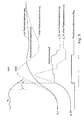
- FIG. 2 shows the exemplary embodiment on the basis of a Flow diagram represents, while in Figure 3 temporal Gradients can be seen.
- Figure 1 shows the reference number 11a to d four wheels of a two-axle vehicle, each Wheel marked with the reference number 12a to d Has wheel speed sensor.
- the wheel speeds will be Nij supplied to the evaluation unit 16.
- Wheel brakes 13a to d are assigned to each wheel 11a to d, the braking force or braking effect through the lines 15a to d is controlled by the evaluation unit 16. Serve for this the control signals Aij.
- Reference number 17 means that the driver can operate it Brake pedal shown.
- the position of the brake pedal 17 is detected and fed to the evaluation unit 16 as signal B. If there is a braking operation, the signal BLS the brake lights 18 driven.
- step 203 a reference wheel selected. To ensure the fastest possible detection, becomes the slowest wheel outside of an anti-lock control of the vehicle selected. In doing so Wheels with speed sensor error, plausibility error, interference or stationary wheels when choosing the slowest Wheel not considered. You can do this in antiblocking systems generally used existing security logic become. Panic brake detection is also used not activated when a rough road is recognized or roadway thresholds, where a wheel course similar to a panic braking can come about. With bad road detection can also on a usually in the anti-lock braking system existing bad road identifier can be used.
- the speed selection be limited to the non-drive axis.
- the speed selection be limited to the non-drive axis. In order to the influence of engine drag torque, especially on Roads with a low coefficient of friction, additionally excluded.
- step 205 the (possibly filtered) wheel acceleration a b is compared with the threshold value SW1.
- the value a b of the wheel acceleration is negative (wheel deceleration).
- the threshold value SW1 delay trigger threshold
- the delay trigger threshold SW1 for example -1m / s 2
- the time counter ⁇ T is started in step 206.
- step 208a the wheel acceleration a b is updated. If the vehicle deceleration threshold SW2 [eg -3 m / s 2 ] is not reached or only after the time window ⁇ T (eg 50 ms) has elapsed, the process goes to final step 211.
- step 209 Further conditions can be checked in step 209 before panic braking is detected in step 210. For example, additional plausibility checks can be carried out in step 209 take place, such as whether the brake light switch (Signal BLS) is activated (driver stands on the Brake) and / or the total vehicle deceleration also from Program cycle to program cycle becomes larger.
- the brake light switch Signal BLS
- FIG. 3 shows an example of the time profiles of different sizes. Above left, the course of the change in time a b of the wheel speed of the reference wheel in the event of panic braking and the threshold values SW1 and SW2 can be seen.
- the course of the vehicle deceleration a_1 is the Brake pressure curve p_Hx on a rear wheel brake with and without Panic brake detection and the panic brake detection flag too see.
- the panic brake detection flag is set (step 210).
- step 210 an adjustable, for example very flat, pulse series for limiting the wheel pressure gradient (valve actuation ABS hydraulics) is started on the wheel brakes of the rear axle (see wheel pressure curve in FIG. 3).
- This gradient limitation runs until ABS control or EBV control (electrical brake force distribution) on the rear axle takes over the pressure modulation, or until a minimum vehicle deceleration (e.g. -2m / s 2 ) is undershot or a maximum set-up time (e.g. 200ms) has been exceeded ,
- panic braking can be carried out for an applicable time following traffic are displayed, for example by the hazard warning lights are activated.
Landscapes
- Engineering & Computer Science (AREA)
- Transportation (AREA)
- Mechanical Engineering (AREA)
- Regulating Braking Force (AREA)
Abstract
Description
- Drehzahlgrößen erfasst werden, die die Drehbewegungen wenigstens zweier Räder repräsentieren,
- die Drehzahlgröße eines der Räder ausgewählt wird und/oder aus den Drehzahlgrößen ein Drehzahlwert ermittelt wird,
- ein die zeitliche Änderung der ausgewählten Drehzahlgröße und/oder des Drehzahlwertes repräsentierender Änderungswert ermittelt wird,
- der zeitliche Verlauf des Änderungswertes ermittelt wird,
- abhängig von dem zeitlichen Verlauf des Änderungswertes eine Panikbremsung erkannt wird.
Claims (11)
- Verfahren zur Erkennung einer Panikbremsung bei einem Kraftfahrzeug mit wenigstens zwei Rädern, wobeiDrehzahlgrößen (Nij) erfasst werden, die die Drehbewegungen wenigstens zweier Räder repräsentieren,die Drehzahlgröße (Nb) eines der Räder ausgewählt wird und/oder aus den Drehzahlgrößen ein Drehzahlwert ermittelt wird,ein die zeitliche Änderung der ausgewählten Drehzahlgröße und/oder des Drehzahlwertes repräsentierender Änderungswert (ab) ermittelt wird,der zeitliche Verlauf des Änderungswertes ermittelt wird,abhängig von dem zeitlichen Verlauf des Änderungswertes (ab) eine Panikbremsung erkannt wird.
- Verfahren nach Anspruch 1, dadurch gekennzeichnet, dass die Drehzahlgröße eines der Räder derart ausgewählt wird,dass als ausgewählte Drehzahlgröße (Nb) die Drehzahlgröße des Rades, das die geringste Drehgeschwindigkeit aufweist, ausgewählt wird, und/oderdass der Drehzahlwert durch eine Mittelwertbildung aus den Drehzahlgrößen wenigstens zweier Räder ermittelt wird.
- Verfahren nach Anspruch 1, dadurch gekennzeichnet, dass die Drehzahlgrößen auf Fehler hin überprüft werden und die Drehzahlgrößen der Räder, an denen ein Fehler detektiert worden ist, von der Auswahl der Drehzahlgröße und/oder von der Ermittlung des Drehzahlwertes ausgeschlossen werden.
- Verfahren nach Anspruch 1, dadurch gekennzeichnet, dass erkannt wird, wenn das Fahrzeug eine Fahrbahn mit Unebenheiten vorgebbaren Ausmaßes befährt und die Erkennung der Panikbremsung bei einer Erkennung des Befahrens einer solchen Fahrbahn deaktiviert wird.
- Verfahren nach Anspruch 1, dadurch gekennzeichnet, dass das Fahrzeug von einem Motor aufweist und wenigstens ein Rad durch den Motor angetrieben wird und zur Auswahl der ausgewählten Drehzahlgröße (Nb) und/oder zur Ermittlung des Drehzahlwertes nur nicht angetriebene Räder herangezogen werden.
- Verfahren nach Anspruch 1, dadurch gekennzeichnet, dassder Änderungswert (ab) mit einem ersten Schwellenwert (SW1) verglichen wird,eine Panikbremsung dann erkannt wird, wenn der Änderungswert (ab) innerhalb einer vorgebbaren ersten Zeitdauer (ΔT) nach dem Unterschreiten des ersten Schwellwertes einen zweiten Schwellenwert (SW2) unterschreitet, wobei der erste Schwellenwert (SW1) größer als der zweite Schwellenwert (SW2) ist.
- Verfahren nach Anspruch 1, dadurch gekennzeichnet, dassdas Fahrzeugs ein vom Fahrer betätigbares Bremspedal aufweist und die ein die Betätigung des Bremspedals repräsentierendes Bremssignal (BLS) erfasst wird und nur dann eine Panikbremsung erkannt wird, wenn das Bremssignal eine Betätigung des Bremspedals anzeigt, und/odereine die Verzögerung des gesamten Fahrzeugs repräsentierende Verzögerungsgröße ermittelt wird und nur dann eine Panikbremsung erkannt wird, wenn die Verzögerungsgröße im zeitlichen Verlauf größer wird.
- Verfahren nach Anspruch 1, dadurch gekennzeichnet, dass in Reaktion auf eine erkannte Panikbremsungeine im Fahrzeug vorgesehene Warnblinkanlage aktiviert wird und/oderder Bremsdruck an den hinteren Rädern begrenzt wird, wobei insbesondere vorgesehen ist, dassdiese Begrenzung solange aufrecht erhalten wird, bis eine Antiblockierregelung und/oder eine Bremskraftverteilungsregelung an den hinteren Rädern aktiviert wird odereine vorgebbare zweite Zeitdauer überschritten wird odereine vorgebbare Fahrzeugmindestverzögerung unterschritten wird.
- Vorrichtung zur Erkennung einer Panikbremsung bei einem Kraftfahrzeug mit wenigstens zwei Rädern, wobei Mittel (16) vorgesehen sind, mittels derDrehzahlgrößen (Nij) erfasst werden, die die Drehbewegungen wenigstens zweier Räder repräsentieren,die Drehzahlgröße (Nb) eines der Räder ausgewählt wird und/oder aus den Drehzahlgrößen ein Drehzahlwert ermittelt wird,ein die zeitliche Änderung der ausgewählten Drehzahlgröße und/oder des Drehzahlwertes repräsentierender Änderungswert (ab) ermittelt wird,der zeitliche Verlauf des Änderungswertes ermittelt wird,abhängig von dem zeitlichen Verlauf des Änderungswertes (ab) eine Panikbremsung erkannt wird.
- Vorrichtung nach Anspruch 9, dadurch gekennzeichnet, dass die Drehzahlgröße eines der Räder derart ausgewählt wird,dass als ausgewählte Drehzahlgröße (Nb) die Drehzahlgröße des Rades, das die geringste Drehgeschwindigkeit aufweist, ausgewählt wird, und/oderdass der Drehzahlwert durch eine Mittelwertbildung aus den Drehzahlgrößen wenigstens zweier Räder ermittelt wird.
- Vorrichtung nach Anspruch 9, dadurch gekennzeichnet, dassder Änderungswert (ab) mit einem ersten Schwellenwert (SW1) verglichen wird,eine Panikbremsung dann erkannt wird, wenn der Änderungswert (ab) innerhalb einer vorgebbaren ersten Zeitdauer (ΔT) nach dem Unterschreiten des ersten Schwellwertes einen zweiten Schwellenwert (SW2) unterschreitet, wobei der erste Schwellenwert (SW1) größer als der zweite Schwellenwert (SW2) ist.
Applications Claiming Priority (4)
| Application Number | Priority Date | Filing Date | Title |
|---|---|---|---|
| DE10031125 | 2000-06-30 | ||
| DE10031125 | 2000-06-30 | ||
| DE10044121 | 2000-09-07 | ||
| DE10044121A DE10044121A1 (de) | 2000-06-30 | 2000-09-07 | Verfahren und Vorrichtung zur Erkennung einer Panikbremsung |
Publications (3)
| Publication Number | Publication Date |
|---|---|
| EP1167143A2 true EP1167143A2 (de) | 2002-01-02 |
| EP1167143A3 EP1167143A3 (de) | 2002-10-02 |
| EP1167143B1 EP1167143B1 (de) | 2010-12-01 |
Family
ID=26006204
Family Applications (1)
| Application Number | Title | Priority Date | Filing Date |
|---|---|---|---|
| EP01113777A Expired - Lifetime EP1167143B1 (de) | 2000-06-30 | 2001-06-06 | Verfahren und Vorrichtung zur Erkennung einer Panikbremsung |
Country Status (3)
| Country | Link |
|---|---|
| US (1) | US6623090B2 (de) |
| EP (1) | EP1167143B1 (de) |
| JP (1) | JP5091375B2 (de) |
Families Citing this family (9)
| Publication number | Priority date | Publication date | Assignee | Title |
|---|---|---|---|---|
| WO2002048581A1 (en) * | 2000-12-11 | 2002-06-20 | Bombardier Inc. | Virtual braking system for hydrostatically driven vehicle |
| JP4554166B2 (ja) * | 2003-04-07 | 2010-09-29 | トヨタ自動車株式会社 | 車輌の制動制御装置 |
| FI20040276L (fi) * | 2004-02-23 | 2005-08-24 | Tom Aalto | Menetelmä auton ja tilanteen hallinnan parantamiseksi hätä- tai täysjarrutustilanteessa |
| DE102004018949A1 (de) * | 2004-04-20 | 2005-11-17 | Daimlerchrysler Ag | Verfahren und Vorrichtung zur Ansteuerung von Bremsmitteln eines Fahrzeugs |
| DE102004021174A1 (de) * | 2004-04-30 | 2005-11-24 | Daimlerchrysler Ag | Verfahren zum Steuern einer sicherheitsrelevanten Komponente eines Kraftfahrzeugs und Kraftfahrzeug mit einem präventiv auslösenden Sicherheitssystem |
| JP5125944B2 (ja) * | 2008-09-25 | 2013-01-23 | トヨタ自動車株式会社 | ブレーキ制御装置 |
| WO2012111799A1 (ja) | 2011-02-18 | 2012-08-23 | 株式会社 アドヴィックス | 車両の制動制御装置及び車両の制動制御方法 |
| DE102013220582A1 (de) * | 2013-10-11 | 2015-04-16 | Continental Teves Ag & Co. Ohg | Verfahren zum Betreiben eines Bremssystems |
| CN104002676A (zh) * | 2014-06-04 | 2014-08-27 | 温州大学 | 一种基于dsp2812控制器的汽车油门误踩判断方法 |
Citations (1)
| Publication number | Priority date | Publication date | Assignee | Title |
|---|---|---|---|---|
| DE19524939A1 (de) | 1995-07-08 | 1997-01-09 | Bosch Gmbh Robert | Verfahren und Vorrichtung zur Steuerung der Bremsanlage eines Fahrzeugs |
Family Cites Families (14)
| Publication number | Priority date | Publication date | Assignee | Title |
|---|---|---|---|---|
| JPS55110648A (en) * | 1979-02-16 | 1980-08-26 | Hitachi Ltd | Skid control device by use of microcomputer |
| US4398260A (en) * | 1979-05-18 | 1983-08-09 | Hitachi, Ltd. | Skid control method |
| JPH04118350A (ja) * | 1990-09-07 | 1992-04-20 | Aisin Seiki Co Ltd | アンチスキッド制御装置 |
| JPH04201772A (ja) * | 1990-11-30 | 1992-07-22 | Mazda Motor Corp | 車両のアンチスキッドブレーキ装置 |
| JP3424965B2 (ja) * | 1993-09-22 | 2003-07-07 | 株式会社日立ユニシアオートモティブ | アンチスキッド制御装置 |
| JPH07195976A (ja) * | 1993-12-29 | 1995-08-01 | Mitsubishi Electric Corp | 車両のストップランプ制御装置 |
| JP3528419B2 (ja) * | 1996-04-26 | 2004-05-17 | トヨタ自動車株式会社 | 制動力制御装置 |
| JP3724053B2 (ja) * | 1996-04-26 | 2005-12-07 | トヨタ自動車株式会社 | 制動力制御装置 |
| JP3684757B2 (ja) * | 1997-06-05 | 2005-08-17 | 日産自動車株式会社 | 車両の制動液圧制御装置 |
| JPH1148951A (ja) * | 1997-08-08 | 1999-02-23 | Toyota Motor Corp | 制動液圧制御装置 |
| US6023221A (en) * | 1997-08-25 | 2000-02-08 | Michelotti; Paul E | System to activate automobile hazard warning lights |
| JP3692777B2 (ja) * | 1998-05-27 | 2005-09-07 | 日産自動車株式会社 | 車両の制動補助装置 |
| DE19936436A1 (de) * | 1999-03-04 | 2001-01-04 | Continental Teves Ag & Co Ohg | Verfahren zum Erkennen einer Notbremssituation |
| US6212461B1 (en) * | 1999-05-28 | 2001-04-03 | General Motors Corporation | Extended brake switch software for vehicle stability enhancement system |
-
2001
- 2001-06-06 EP EP01113777A patent/EP1167143B1/de not_active Expired - Lifetime
- 2001-06-20 JP JP2001186189A patent/JP5091375B2/ja not_active Expired - Fee Related
- 2001-07-02 US US09/897,009 patent/US6623090B2/en not_active Expired - Lifetime
Patent Citations (1)
| Publication number | Priority date | Publication date | Assignee | Title |
|---|---|---|---|---|
| DE19524939A1 (de) | 1995-07-08 | 1997-01-09 | Bosch Gmbh Robert | Verfahren und Vorrichtung zur Steuerung der Bremsanlage eines Fahrzeugs |
Also Published As
| Publication number | Publication date |
|---|---|
| JP2002037041A (ja) | 2002-02-06 |
| US6623090B2 (en) | 2003-09-23 |
| EP1167143B1 (de) | 2010-12-01 |
| EP1167143A3 (de) | 2002-10-02 |
| JP5091375B2 (ja) | 2012-12-05 |
| US20020027389A1 (en) | 2002-03-07 |
Similar Documents
| Publication | Publication Date | Title |
|---|---|---|
| EP1574400B1 (de) | Verfahren zum Ansteuern eines reversiblen Insassenschutzmittels in einem Kraftfahrzeug | |
| DE19901953B4 (de) | Vorrichtung und Verfahren zur Stabilisierung eines Fahrzeuggespannes | |
| EP1142768B1 (de) | Verfahren zur Vermeidung des Umkippens eines Fahrzeuges um seine Längsachse | |
| EP1687183B1 (de) | Verfahren und einrichtung zur verringerung von unfallschäden | |
| EP1601561B1 (de) | Verfahren und system zur regelung der fahrstabilität eines fahrzeugs und verwendung des systems | |
| DE19933084B4 (de) | Verfahren und Vorrichtung zur Steuerung des Schlupfes eines Fahrzeugrades | |
| EP1399344B1 (de) | Verfahren zur regelung der fahrstabilität | |
| DE4418070C1 (de) | Verfahren zum Abgleichen der Raddrehzahlen für ein Kraftfahrzeug | |
| DE60126025T2 (de) | Warnungseinrichtung und -verfahren für ein Fahrzeug | |
| WO2000003887A1 (de) | Verfahren und einrichtung zum erfassen der gefahr des umkippens eines kraftfahrzeugs | |
| DE19814574A1 (de) | System zur Erzeugung eines Signals zur Ansteuerung der Bremsleuchten eines Kraftfahrzeugs | |
| DE102011077153B4 (de) | Verfahren zum Modifizieren einer Fahrstabilitätsregelung eines Fahrzeugs und Elektronisches Steuergerät | |
| DE19949286B4 (de) | Vorrichtung und Verfahren zur Regelung wenigstens einer Fahrzeugbewegungsgrösse | |
| DE102008011577A1 (de) | Verfahren und Vorrichtung zur Stabilisierung eines einspurigen Kraftfahrzeugs | |
| DE19708508A1 (de) | Verfahren und Vorrichtung zur Regelung einer die Fahrzeugbewegung repräsentierenden Bewegungsgröße | |
| DE19738611A1 (de) | Automatische Notbremsfunktion | |
| EP1045783B1 (de) | Vorrichtung und verfahren zum begrenzen einer rückrollgeschwindigkeit eines kraftfahrzeuges | |
| EP1131235B1 (de) | Verfahren und vorrichtung zur stabilisierung eines mit einer schlupfgeregelten bremsanlage ausgestatteten fahrzeugs | |
| DE19611491A1 (de) | System zur Ansteuerung eines Bremssystems | |
| DE19958772A1 (de) | Verfahren und Vorrichtung zur Antriebsschlupfregelung (ASR) eines Kraftfahrzeugs in Abhängigkeit von Kurvenradius und Querbeschleunigung | |
| EP1167143A2 (de) | Verfahren und Vorrichtung zur Erkennung einer Panikbremsung | |
| DE10031128B4 (de) | Verfahren und Vorrichtung zur Erkennung eines Spurwechsels | |
| EP0844954B1 (de) | Verfahren und vorrichtung zur steuerung der bremsanlage eines fahrzeugs | |
| EP1571058A1 (de) | Verfahren zur Abbremsung eines Fahrzeuges | |
| EP0859712B1 (de) | Verfahren und vorrichtung zur regelung einer die fahrzeugbewegung repräsentierenden bewegungsgrösse |
Legal Events
| Date | Code | Title | Description |
|---|---|---|---|
| PUAI | Public reference made under article 153(3) epc to a published international application that has entered the european phase |
Free format text: ORIGINAL CODE: 0009012 |
|
| AK | Designated contracting states |
Kind code of ref document: A2 Designated state(s): AT BE CH CY DE DK ES FI FR GB GR IE IT LI LU MC NL PT SE TR |
|
| AX | Request for extension of the european patent |
Free format text: AL;LT;LV;MK;RO;SI |
|
| PUAL | Search report despatched |
Free format text: ORIGINAL CODE: 0009013 |
|
| AK | Designated contracting states |
Kind code of ref document: A3 Designated state(s): AT BE CH CY DE DK ES FI FR GB GR IE IT LI LU MC NL PT SE TR |
|
| AX | Request for extension of the european patent |
Free format text: AL;LT;LV;MK;RO;SI |
|
| 17P | Request for examination filed |
Effective date: 20030402 |
|
| AKX | Designation fees paid |
Designated state(s): DE ES GB SE |
|
| 17Q | First examination report despatched |
Effective date: 20070302 |
|
| GRAP | Despatch of communication of intention to grant a patent |
Free format text: ORIGINAL CODE: EPIDOSNIGR1 |
|
| RIC1 | Information provided on ipc code assigned before grant |
Ipc: B60T 8/17 20060101AFI20100728BHEP |
|
| GRAS | Grant fee paid |
Free format text: ORIGINAL CODE: EPIDOSNIGR3 |
|
| GRAA | (expected) grant |
Free format text: ORIGINAL CODE: 0009210 |
|
| AK | Designated contracting states |
Kind code of ref document: B1 Designated state(s): DE ES GB SE |
|
| REG | Reference to a national code |
Ref country code: GB Ref legal event code: FG4D Free format text: NOT ENGLISH |
|
| REF | Corresponds to: |
Ref document number: 50115723 Country of ref document: DE Date of ref document: 20110113 Kind code of ref document: P |
|
| REG | Reference to a national code |
Ref country code: SE Ref legal event code: TRGR |
|
| REG | Reference to a national code |
Ref country code: ES Ref legal event code: FG2A Ref document number: 2355961 Country of ref document: ES Kind code of ref document: T3 Effective date: 20110401 |
|
| PLBE | No opposition filed within time limit |
Free format text: ORIGINAL CODE: 0009261 |
|
| STAA | Information on the status of an ep patent application or granted ep patent |
Free format text: STATUS: NO OPPOSITION FILED WITHIN TIME LIMIT |
|
| 26N | No opposition filed |
Effective date: 20110902 |
|
| REG | Reference to a national code |
Ref country code: DE Ref legal event code: R097 Ref document number: 50115723 Country of ref document: DE Effective date: 20110902 |
|
| PGFP | Annual fee paid to national office [announced via postgrant information from national office to epo] |
Ref country code: ES Payment date: 20120628 Year of fee payment: 12 |
|
| PGFP | Annual fee paid to national office [announced via postgrant information from national office to epo] |
Ref country code: GB Payment date: 20130620 Year of fee payment: 13 |
|
| GBPC | Gb: european patent ceased through non-payment of renewal fee |
Effective date: 20140606 |
|
| PG25 | Lapsed in a contracting state [announced via postgrant information from national office to epo] |
Ref country code: GB Free format text: LAPSE BECAUSE OF NON-PAYMENT OF DUE FEES Effective date: 20140606 |
|
| REG | Reference to a national code |
Ref country code: ES Ref legal event code: FD2A Effective date: 20150728 |
|
| PG25 | Lapsed in a contracting state [announced via postgrant information from national office to epo] |
Ref country code: ES Free format text: LAPSE BECAUSE OF NON-PAYMENT OF DUE FEES Effective date: 20140607 |
|
| PGFP | Annual fee paid to national office [announced via postgrant information from national office to epo] |
Ref country code: SE Payment date: 20160621 Year of fee payment: 16 |
|
| REG | Reference to a national code |
Ref country code: SE Ref legal event code: EUG |
|
| PG25 | Lapsed in a contracting state [announced via postgrant information from national office to epo] |
Ref country code: SE Free format text: LAPSE BECAUSE OF NON-PAYMENT OF DUE FEES Effective date: 20170607 |
|
| PGFP | Annual fee paid to national office [announced via postgrant information from national office to epo] |
Ref country code: DE Payment date: 20190822 Year of fee payment: 19 |
|
| REG | Reference to a national code |
Ref country code: DE Ref legal event code: R119 Ref document number: 50115723 Country of ref document: DE |
|
| PG25 | Lapsed in a contracting state [announced via postgrant information from national office to epo] |
Ref country code: DE Free format text: LAPSE BECAUSE OF NON-PAYMENT OF DUE FEES Effective date: 20210101 |