EP1166898A2 - Device for the continuous, mechanical cleaning of the outer surface of round rolled stock and tubes by removing scale and/or rust - Google Patents
Device for the continuous, mechanical cleaning of the outer surface of round rolled stock and tubes by removing scale and/or rust Download PDFInfo
- Publication number
- EP1166898A2 EP1166898A2 EP01250219A EP01250219A EP1166898A2 EP 1166898 A2 EP1166898 A2 EP 1166898A2 EP 01250219 A EP01250219 A EP 01250219A EP 01250219 A EP01250219 A EP 01250219A EP 1166898 A2 EP1166898 A2 EP 1166898A2
- Authority
- EP
- European Patent Office
- Prior art keywords
- drive
- spindle
- cleaning
- support
- spindle element
- Prior art date
- Legal status (The legal status is an assumption and is not a legal conclusion. Google has not performed a legal analysis and makes no representation as to the accuracy of the status listed.)
- Withdrawn
Links
- 238000004140 cleaning Methods 0.000 title claims abstract description 32
- JEIPFZHSYJVQDO-UHFFFAOYSA-N iron(III) oxide Inorganic materials O=[Fe]O[Fe]=O JEIPFZHSYJVQDO-UHFFFAOYSA-N 0.000 title claims description 4
- 239000012459 cleaning agent Substances 0.000 claims description 3
- 238000005096 rolling process Methods 0.000 claims 1
- 239000000969 carrier Substances 0.000 abstract 1
- 238000011086 high cleaning Methods 0.000 description 2
- 125000006850 spacer group Chemical group 0.000 description 2
- 229910000831 Steel Inorganic materials 0.000 description 1
- 230000001066 destructive effect Effects 0.000 description 1
- 238000010438 heat treatment Methods 0.000 description 1
- 238000004519 manufacturing process Methods 0.000 description 1
- 239000000463 material Substances 0.000 description 1
- 239000010959 steel Substances 0.000 description 1
- 238000005496 tempering Methods 0.000 description 1
- 238000011144 upstream manufacturing Methods 0.000 description 1
- 238000011179 visual inspection Methods 0.000 description 1
Images


Classifications
-
- B—PERFORMING OPERATIONS; TRANSPORTING
- B08—CLEANING
- B08B—CLEANING IN GENERAL; PREVENTION OF FOULING IN GENERAL
- B08B9/00—Cleaning hollow articles by methods or apparatus specially adapted thereto
- B08B9/02—Cleaning pipes or tubes or systems of pipes or tubes
- B08B9/023—Cleaning the external surface
-
- B08B1/20—
-
- B08B1/32—
-
- B—PERFORMING OPERATIONS; TRANSPORTING
- B21—MECHANICAL METAL-WORKING WITHOUT ESSENTIALLY REMOVING MATERIAL; PUNCHING METAL
- B21B—ROLLING OF METAL
- B21B45/00—Devices for surface or other treatment of work, specially combined with or arranged in, or specially adapted for use in connection with, metal-rolling mills
- B21B45/04—Devices for surface or other treatment of work, specially combined with or arranged in, or specially adapted for use in connection with, metal-rolling mills for de-scaling, e.g. by brushing
-
- B—PERFORMING OPERATIONS; TRANSPORTING
- B21—MECHANICAL METAL-WORKING WITHOUT ESSENTIALLY REMOVING MATERIAL; PUNCHING METAL
- B21C—MANUFACTURE OF METAL SHEETS, WIRE, RODS, TUBES OR PROFILES, OTHERWISE THAN BY ROLLING; AUXILIARY OPERATIONS USED IN CONNECTION WITH METAL-WORKING WITHOUT ESSENTIALLY REMOVING MATERIAL
- B21C43/00—Devices for cleaning metal products combined with or specially adapted for use with machines or apparatus provided for in this subclass
- B21C43/02—Devices for cleaning metal products combined with or specially adapted for use with machines or apparatus provided for in this subclass combined with or specially adapted for use in connection with drawing or winding machines or apparatus
- B21C43/04—Devices for de-scaling wire or like flexible work
Definitions
- the invention relates to a device for continuous mechanical cleaning according to the outer surface of round rolled material and tubes of scale and / or rust the preamble of claim 1.
- a generic device is known from DE-OS 1527 653. This points one arranged between driving feed and replenishment rollers Cleaning device on that with a workpiece to be cleaned compressible cutting tool and a device for rotating the tool around its own axis and around the axis of the workpiece to be machined is provided.
- the cutting tool is a needle mill, which is driven by a planetary gear on the one hand set in its own rotation and on the other hand in circulation around the Workpiece is rotated.
- the disadvantage of this arrangement is the high one technical effort and the low cleaning performance.
- the object of the invention is to provide a structurally simple device for continuous mechanical cleaning of the outer surface of round rolled stock and Specify pipes of scale and / or rust with a high cleaning performance is achievable.
- the cleaning device is offset by three by 120 ° arranged, each separately drivable supports provided on which interchangeably arranged a cylindrical brush as a cleaning agent is.
- the workpiece turns around its own longitudinal axis Cleaning device supplied.
- Each carrier consists of a stored one Support spindle and a mounted drive spindle, which are independent of each other in a frame part of the Housing are radially adjustable and braced against each other.
- each drive spindle is preferably with one High power electric motor connected.
- the respective brush is between the Drive spindle and the support spindle added, the support spindle axially can be moved so that the brush can be easily installed and removed.
- Each drive spindle and each support spindle are included for the radial adjustment of the brush provided a lifting element.
- the lifting elements can but can also be controlled individually so that the brush can be tilted is.
- the proposed cleaning device can be set up and operated separately are, but preferably it is integrated in a production line. For one thing, could on a finishing line before carrying out the non-destructive tests and / or the visual inspection. Another application is Cleaning of pipes scaled after tempering Heat treatment still need to be addressed. Preferably one could Install the device in front of or after the straightening system.
- the first line-up would have the advantage that there is a risk of loose scale being pressed in during straightening is reduced by the upstream cleaning.
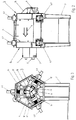
- FIG. 1 shows a perspective view and Figure 2 in a longitudinal view and FIG. 3 shows a front view of a device designed according to the invention Cleaning device 1.
- Two frame parts 3, 4 are attached to a support frame 2 with a cover that can be folded away in between 5.
- On each as Hexagonally formed frame part 3, 4 (FIG. 4) are three that are offset by 120 ° Lifting elements 6.1.6.1 ', 6.1 ", 6.2.6.2', 6.2" arranged.
- FIG. 4 it is good to recognize that three radially adjustable supports are provided in the frame part 3, the are offset by 120 ° to each other.
- Each carrier is with its own drive 7,7 ', 7 " Mistake.
- FIG. 1 shows the Arrow 9 in Figure 1 and Figure 2 shows the transport direction of the workpiece 8 through the Features cleaning device 1.
- Figure 4 shows a perspective Representation of a frame element 3. It consists of 6 panels 10.1,10.1 ', 10.1 ", 11.1,11.1', 11.1", of which three are always of the same design and all together form a hexagon.
- the plates at 12 p.m., 4 a.m. and 8 a.m. 10.1,10.1 ', 10.1 have openings 12.1, 12.1', 12.1" around the lifting elements 6.1.6.1 ', 6.1 ".
- FIGS. 6 to 8 show the details of a support spindle element 18 shown.
- This element 18 consists of an adjusting spindle 19 and one therein axially displaceably inserted support mandrel 20.
- the adjusting spindle 19 is comprised of a support sleeve 21 into which a socket 22 is inserted on the output side.
- two roller bearings 23, 24 are arranged at a distance from one another with a spacer sleeve 25 in between.
- the outer rings of the roller bearings 23, 24 are supported on the outside on square flanges 26, 27 by four Bars 28 are braced against each other.
- the outer end is two Lid 29,30, the latter lid 30 can be secured by a nut 31.
- the outer section 32 of the adjusting spindle 19 is designed as a hexagon, in order to be able to attach a hexagon bowl to it.
- the possibility of twisting the Adjustment spindle 19 can be blocked by a lock nut 63.
- the front section 33 of the support mandrel 20 is designed as a cone to have an end thereon To be able to attach cleaning brush 34 (FIG. 11, FIG. 12).
- the support mandrel 20 can be axially displaced in order to easily install and remove the cleaning brush 24 to be able to.
- the adjusting spindle 19 has a front area Threaded section 35 and the support mandrel 20 also in the rear area Threaded section 36.
- the direction of pitch of both thread sections is 35, 36 in opposite directions, d. H.
- one threaded portion 35 is clockwise and the other Threaded portion 36 is formed counterclockwise. So when turning the Adjustment spindle 19 due to the friction, the support mandrel 20 cannot rotate on the end of the socket 22, a rotation lock 37 is fastened, which is inserted into a long groove 38 of the support mandrel 20 engages.
- the counterpart to the support spindle element 18 is the drive spindle element 39 ( Figure 9, Figure 10).
- This element 39 consists of a drive spindle 40, on the two roller bearings 41, 42 located at a distance from one another are arranged. Between a spacer sleeve 43 is provided. The outer rings of the roller bearings 41, 42 are supported on the outside on two flanges 44, 45 by the rods, not shown here are also braced against each other. The outer end is two Cover 46, 47, the first-mentioned cover 46 being secured by a nut 48.
- the area of the drive spindle 40 on the drive side has a recess 49 for receiving an output pin of an electric motor.
- the output side lying area has a section 50 which is a square truncated pyramid is trained.
- a fully assembled rotatable carrier is shown as an example in FIG.
- the main elements of this carrier are the drive 7, preferably an electric motor high performance, the drive spindle element 39, the support spindle element 18 and the intermediate cleaning brush 34. So that the end face of the in Cleaning device 1 incoming workpiece 8 to be cleaned (FIG. 2) not on the Cleaning brush 34 can brake, is on the inlet side Thrust washer 51 and a drain disc 52 arranged on the discharge side. Both Disks 51, 52 are seen in the transport direction 9 with a conical design End face 53,54 provided.
- Figure 12 shows the details of the arrangement of the Cleaning brush 34.
- the preferably with radially protruding steel wires provided cleaning brush 34 is arranged on a support sleeve 55, each on both sides is closed with a welded cover 58, 58 '.
- the support sleeve 55 On the overhanging part the support sleeve 55 is each a flange 56,57 attached. Both flanges 56.57 each have a recess 59, 60, once for receiving the support mandrel 20 and others for receiving the drive spindle 40.
Abstract
Description
Die Erfindung betrifft eine Vorrichtung zum kontinuierlichen mechanischen Reinigen der Außenfläche von rundem Walzgut und Rohren von Zunder und/oder Rost gemäß dem Oberbegriff des Patentanspruches 1.The invention relates to a device for continuous mechanical cleaning according to the outer surface of round rolled material and tubes of scale and / or rust the preamble of claim 1.
Eine gattungsbildende Vorrichtung ist aus der DE-OS 1527 653 bekannt. Diese weist eine zwischen treibenden Vor-und Nachschubrollen angeordnete Reinigungsvorrichtung auf, die mit einem an das zu reinigende Werkstück anpressbaren Schneidwerkzeug und einer Vorrichtung zur Drehung des Werkzeuges um seine eigene Achse sowie um die Achse des zu bearbeitenden Werkstückes versehen ist. Das Schneidwerkzeug ist ein Nadelfräser, der durch ein Planetengetriebe zum einen in eigene Rotation versetzt wird und zum anderen im Umlauf um das Werkstück gedreht wird. Nachteilig bei dieser Anordnung ist der hohe getriebetechnische Aufwand und die geringe Reinigungsleistung.A generic device is known from DE-OS 1527 653. This points one arranged between driving feed and replenishment rollers Cleaning device on that with a workpiece to be cleaned compressible cutting tool and a device for rotating the tool around its own axis and around the axis of the workpiece to be machined is provided. The cutting tool is a needle mill, which is driven by a planetary gear on the one hand set in its own rotation and on the other hand in circulation around the Workpiece is rotated. The disadvantage of this arrangement is the high one technical effort and the low cleaning performance.
Aufgabe der Erfindung ist es, eine konstruktiv einfache Vorrichtung zum kontinuierlichen mechanischen Reinigen der Außenfläche von rundem Walzgut und Rohren von Zunder und/oder Rost anzugeben, mit der eine hohe Reinigungsleistung erzielbar ist.The object of the invention is to provide a structurally simple device for continuous mechanical cleaning of the outer surface of round rolled stock and Specify pipes of scale and / or rust with a high cleaning performance is achievable.
Diese Aufgabe wird ausgehend vom Oberbegriff in Verbindung mit den kennzeichnenden Merkmalen des Anspruches 1 gelöst. Vorteilhafte Weiterbildungen sind jeweils Gegenstand von Unteransprüchen. This task is based on the generic term in conjunction with the characterizing features of claim 1 solved. Advantageous further training are the subject of subclaims.
Nach der Lehre der Erfindung ist die Reinigungsvorrichtung mit drei um 120° versetzt angeordneten, jeweils separat antreibbaren Trägern versehen, auf denen auswechselbar je eine zylindrisch ausgebildete Bürste als Reinigungsmittel angeordnet ist. Das Werkstück wird um die eigene Längsachse sich drehend dieser Reinigungsvorrichtung zugeführt. Jeder Träger besteht aus einer gelagerten Stützspindel und einer gelagerten Antriebsspindel, die unabhängig voneinander in einem eingangsseitig und einem ausgangsseitig vorgesehenen Rahmenteil des Gehäuses radial verstellbar angeordnet und gegeneinander verspannbar sind. Um eine hohe Reinigungsleistung zu erreichen,ist jede Antriebsspindel vorzugsweise mit einem Elektromotor hoher Leistung verbunden. Die jeweilige Bürste wird zwischen der Antriebsspindel und der Stützspindel aufgenommen, wobei die Stützspindel axial verschoben werden kann, um die Bürste problemlos ein- und ausbauen zu können.According to the teaching of the invention, the cleaning device is offset by three by 120 ° arranged, each separately drivable supports provided on which interchangeably arranged a cylindrical brush as a cleaning agent is. The workpiece turns around its own longitudinal axis Cleaning device supplied. Each carrier consists of a stored one Support spindle and a mounted drive spindle, which are independent of each other in a frame part of the Housing are radially adjustable and braced against each other. To one To achieve high cleaning performance, each drive spindle is preferably with one High power electric motor connected. The respective brush is between the Drive spindle and the support spindle added, the support spindle axially can be moved so that the brush can be easily installed and removed.
Zur radialen Verstellung der Bürste ist jede Antriebsspindel und jede Stützspindel mit einem Hubelement versehen. Diese können paarweise zusammengefasst werden, so dass die Bürste achsparallel radial verstellt werden kann. Die Hubelemente können aber auch einzeln angesteuert werden, so dass eine Schiefstellung der Bürste möglich ist.Each drive spindle and each support spindle are included for the radial adjustment of the brush provided a lifting element. These can be summarized in pairs, see above that the brush can be adjusted radially parallel to the axis. The lifting elements can but can also be controlled individually so that the brush can be tilted is.
Die vorgeschlagene Reinigungsvorrichtung kann separat aufgestellt und betrieben werden, vorzugsweise ist sie aber in einer Fertigungslinie integriert. Zum einen könnte sie in einer Adjustagelinie vor Durchführung der zerstörungsfreien Prüfungen und/oder der Sichtprüfung aufgestellt werden. Eine andere Anwendungsmöglichkeit ist die Reinigung von nach einem Vergüten verzunderten Rohren, die nach der Wärmebehandlung noch gerichtet werden müssen. Vorzugsweise könnte man die Vorrichtung vor der Richtanlage oder danach aufstellen. Die erstgenannte Aufstellung hätte den Vorteil, dass die Gefahr eines Eindrücken von losem Zunder beim Richten durch die vorgeschaltete Reinigung verringert wird.The proposed cleaning device can be set up and operated separately are, but preferably it is integrated in a production line. For one thing, could on a finishing line before carrying out the non-destructive tests and / or the visual inspection. Another application is Cleaning of pipes scaled after tempering Heat treatment still need to be addressed. Preferably one could Install the device in front of or after the straightening system. The first line-up would have the advantage that there is a risk of loose scale being pressed in during straightening is reduced by the upstream cleaning.
Weitere Merkmale, Vorteile und Einzelheiten der Erfindung ergeben sich aus der nachfolgenden Beschreibung von einem in einer Zeichnung dargestellten Ausführungsbeispiel. Es zeigen:
- Figur 1
- in einer perspektivischen Darstellung eine erfindungsmäßig ausgebildete Reinigungsvorrichtung
Figur 2- eine Seitenansicht von Figur 1
Figur 3- eine Vorderansicht von Figur 1
- Figur 4
- in einer perspektivischen Darstellung ein Rahmenteil
- Figur 5
- in einer perspektivischen Darstellung ein Element des Zuführtrichters
- Figur 6
- eine Außenansicht eines Stützspindelelementes
Figur 7- eine Vorderansicht von Figur 6
Figur 8- einen Schnitt in Richtung A-A in
Figur 7 - Figur 9
- eine Vorderansicht eines Antriebsspindelelementes
- Figur 10
- einen Schnitt in Richtung A-A in Figur 9
- Figur 11
- in einer Längsansicht einen Träger einschließlich Antrieb
- Figur 12
- eine Anordnung einer Reinigungsbürste im Schnitt
- Figure 1
- a perspective view of a cleaning device designed according to the invention
- Figure 2
- 2 shows a side view of FIG. 1
- Figure 3
- a front view of Figure 1
- Figure 4
- in a perspective view a frame part
- Figure 5
- a perspective view of an element of the feed hopper
- Figure 6
- an external view of a support spindle element
- Figure 7
- a front view of Figure 6
- Figure 8
- a section in the direction AA in Figure 7
- Figure 9
- a front view of a drive spindle element
- Figure 10
- a section in the direction AA in Figure 9
- Figure 11
- in a longitudinal view a carrier including drive
- Figure 12
- an arrangement of a cleaning brush in section
Figur 1 zeigt in einer perspektivischen Darstellung und Figur 2 in einer Längsansicht
und Figur 3 in einer Vorderansicht eine erfindungsgemäß ausgebildete
Reinigungsvorrichtung 1. Auf einem Traggestell 2 sind zwei Rahmenteile 3,4 befestigt
mit einer dazwischen liegenden wegklappbaren Abdeckung 5. Auf jedem als
Sechskant ausgebildeten Rahmenteil 3,4 (Figur 4) sind drei um 120° versetzt liegende
Hubelemente 6.1,6.1',6.1",6.2,6.2',6.2" angeordnet. Speziell in Figur 3 ist gut zu
erkennen, dass im Rahmenteil 3 drei radial verstellbare Träger vorgesehen sind, die
um 120° zueinander versetzt liegen. Jeder Träger ist mit einem eigenen Antrieb 7,7',7"
versehen. Das zu reinigende Werkstück 8 ist hier symbolhaft dargestellt, wobei der
Pfeil 9 in Figur 1 und Figur 2 die Transportrichtung des Werkstückes 8 durch die
Reinigungsvorrichtung 1 kennzeichnet. Figur 4 zeigt in einer perspektivischen
Darstellung ein Rahmenelement 3. Es besteht aus 6 Platten
10.1,10.1',10.1",11.1,11.1',11.1", wovon immer drei gleich ausgebildet sind und alle
zusammen ein Sechseck bilden. Die in 12 Uhr, 4 Uhr und 8 Uhr liegenden Platten
10.1,10.1',10.1" weisen Öffnungen 12.1,12.1',12.1" auf, um die Hubelemente
6.1,6.1',6.1" aufnehmen zu können. Innerhalb des Rahmenelementes 3 sind drei
dreieckig ausgebildete Stegbleche 13.1,13.1',13.1" eingeschweißt, deren zueinander
parallel liegende Dreiecksseiten einen Zwischenraum bilden zur Führung des in Figur 5
dargestellten Kulissensteins 14. Gemäß Figur 5 sind am Kulissenstein 14
eingangsseitig drei plattenartige Segmente 15,16,17 angeschweißt, die zusammen den
Zuführtrichter bilden. Figure 1 shows a perspective view and Figure 2 in a longitudinal view
and FIG. 3 shows a front view of a device designed according to the invention
Cleaning device 1. Two
In den Figuren 6 bis 8 sind die Einzelheiten eines Stützspindelelementes 18
dargestellt. Dieses Element 18 besteht aus einer Verstellspindel 19 und einem darin
axial verschiebbar eingesteckten Stützdorn 20. Die Verstellspindel 19 wird umfasst von
einer Traghülse 21, in die ausgangsseitig eine Buchse 22 eingesteckt ist. Auf der
Traghülse 21 sind zwei im Abstand voneinander liegende Wälzlager 23,24 angeordnet
mit einer dazwischen liegenden Distanzhülse 25. Die Außenringe der Wälzlager 23,24
stützen sich außenseitig auf viereckig ausgebildete Flansche 26,27 ab, die durch vier
Stangen 28 gegeneinander verspannbar sind. Den äußeren Abschluss bilden zwei
Deckel 29,30, wobei der letztgenannte Deckel 30 durch eine Mutter 31 sicherbar ist.
Der außen liegende Abschnitt 32 der Verstellspindel 19 ist als Sechskant ausgebildet,
um daran einen Sechskantschüssel ansetzen zu können. Die Verdrehmöglichkeit der
Verstellspindel 19 ist durch eine Kontermutter 63 blockierbar. Der vordere Abschnitt 33
des Stützdornes 20 ist als Kegel ausgebildet, um darauf ein Ende einer
Reinigungsbürste 34 (Figur 11, Figur 12) aufstecken zu können. Der Stützdorn 20 kann
axial verschoben werden, um die Reinigungsbürste 24 problemlos ein- und ausbauen
zu können. Dazu weist die Verstellspindel 19 im vorderen Bereich ein
Gewindeabschnitt 35 und der Stützdorn 20 im hinteren Bereich ebenfalls ein
Gewindeabschnitt 36 auf. Die Steigungsrichtung beider Gewindeabschnitte 35,36 ist
gegenläufig, d. h. ein Gewindeabschnitt 35 ist rechtsdrehend und der andere
Gewindeabschnitt 36 ist linksdrehend ausgebildet. Damit beim Drehen der
Verstellspindel 19 infolge der Reibung sich der Stützdorn 20 nicht mitdrehen kann, ist
an der Buchse 22 stirnseitig eine Drehsicherung 37 befestigt, die in eine Langnut 38
des Stützdornes 20 eingreift.FIGS. 6 to 8 show the details of a
Das Gegenstück zum Stützspindelelement 18 stellt das Antriebsspindelelement 39 dar
(Figur 9, Figur 10). Dieses Element 39 besteht aus einer Antriebsspindel 40, auf der
zwei im Abstand voneinander liegende Wälzlager 41,42 angeordnet sind. Dazwischen
ist eine Distanzhülse 43 vorgesehen. Die Außenringe der Wälzlager 41,42 stützen sich
außenseitig auf zwei Flansche 44,45 ab, die durch hier nicht dargestellte Stangen
ebenfalls gegeneinander verspannbar sind. Den äußeren Abschluss bilden zwei
Deckel 46,47, wobei der erstgenannte Deckel 46 durch eine Mutter 48 sicherbar ist.
Der antriebsseitig liegende Bereich der Antriebsspindel 40 weist eine Ausnehmung 49
zur Aufnahme eines Abtriebszapfens eines Elektromotors auf. Der abtriebsseitig
liegende Bereich weist einen Abschnitt 50 auf, der als viereckiger Pyramidenstumpf
ausgebildet ist. The counterpart to the
In Figur 11 ist beispielhaft ein vollständig montierter drehbarer Träger dargestellt. Die
Hauptelemente dieses Trägers sind der Antrieb 7, vorzugsweise ein Elektromotor
hoher Leistung, das Antriebsspindelelement 39, das Stützspindelelement 18 sowie die
dazwischen liegende Reinigungsbürste 34. Damit die Stirnseite des in die
Reinigungsvorrichtung 1 einlaufende zu reinigende Werkstück 8 (Figur 2) nicht auf die
Reinigungsbürste 34 abbremsend auflaufen kann, ist auf der Einlaufseite eine
Auflaufscheibe 51 und auf der Ablaufseite eine Ablaufscheibe 52 angeordnet. Beide
Scheiben 51, 52 sind in Transportrichtung 9 gesehen mit einer kegelig ausgebildeten
Stirnfläche 53,54 versehen. Figur 12 zeigt die Einzelheiten der Anordnung der
Reinigungsbürste 34. Die vorzugsweise mit radial abstehenden Stahldrähten
versehene Reinigungsbürste 34 ist auf einer Traghülse 55 angeordnet, die beidseitig je
mit einem angeschweißten Deckel 58, 58' verschlossen ist. Am überhängenden Teil
der Traghülse 55 ist je ein Flansch 56,57 befestigt. Beide Flansche 56,57 weisen je
eine Ausnehmung 59, 60 auf, einmal zur Aufnahme des Stützdornes 20 und zum
anderen zur Aufnahme der Antriebsspindel 40. Auf den Flanschen 56,57 sind
einlaufseitig die Auflaufscheibe 51 und ablaufseitig die Ablaufscheibe 52 aufgesteckt.
Gehalten wird diese Kombination durch Stangen 61, die sich durch alle genannten
Teile erstrecken und gesichert werden durch die an den Enden aufschraubbaren
Muttern 62. A fully assembled rotatable carrier is shown as an example in FIG. The
The main elements of this carrier are the
Claims (14)
dadurch gekennzeichnet, dass bei einem der Reinigungsvorrichtung (1) zugeführten, um die eigene Längsachse sich drehenden Werkstück (8) die Reinigungsvorrichtung (1) drei um 120° versetzt angeordnete, jeweils separat antreibbare Träger aufweist, auf denen auswechselbar je eine zylindrisch ausgebildete Bürste (34) als Reinigungsmittel angeordnet ist.Device for the continuous mechanical cleaning of the outer surface of round rolling stock and pipes of scale and / or rust, which has at least one drivable cleaning agent which can be pressed radially onto the workpiece to be cleaned,
characterized in that in the case of a workpiece (8) which is fed to the cleaning device (1) and rotates about its own longitudinal axis, the cleaning device (1) has three supports which are arranged at 120 ° and are each separately drivable, on each of which a cylindrical brush ( 34) is arranged as a cleaning agent.
dadurch gekennzeichnet, dass jeder Träger aus einem gelagerten Stützspindelelement (18) und einem gelagerten Antriebsspindelelement (39) besteht, die unabhängig voneinander in einem eingangseitig und einem ausgangsseitig vorgesehenen Rahmenteil (3,4) verstellbar angeordnet und gegeneinander verspannbar sind.Device according to claim 1,
characterized in that each carrier consists of a supported support spindle element (18) and a mounted drive spindle element (39) which are arranged independently of one another in a frame part (3, 4) provided on the input side and on the output side and can be braced against one another.
dadurch gekennzeichnet, dass jedes Antriebsspindelelement (39) mit einem eigenen Antrieb (7) verbunden ist.Device according to claims 1 and 2,
characterized in that each drive spindle element (39) is connected to its own drive (7).
dadurch gekennzeichnet, dass jede Antriebsspindel (40) auf der Antriebsseite eine Aufnahme (49) für den Antrieb (7) und auf der Abtriebsseite eine Aufnahme (50) für die Reinigungsbürste (34) aufweist.Device according to claims 1 to 3,
characterized in that each drive spindle (40) has a receptacle (49) for the drive (7) on the drive side and a receptacle (50) for the cleaning brush (34) on the driven side.
dadurch gekennzeichnet, dass die Aufnahme (50) für die Reinigungsbürste (34) als viereckiger Pyramidenstumpf ausgebildet ist.Device according to claim 4,
characterized in that the receptacle (50) for the cleaning brush (34) is designed as a square truncated pyramid.
dadurch gekennzeichnet, dass jedes Stützspindelelement (18) mit einer drehbaren Verstellspindel (19) und einem darin drehgesicherten Stützdorn (20) versehen ist.Device according to claims 1 and 2,
characterized in that each support spindle element (18) is provided with a rotatable adjusting spindle (19) and a support mandrel (20) secured against rotation therein.
dadurch gekennzeichnet, dass das der Vorrichtung (1) abgewandte Ende der Verstellspindel (19) als Sechskant ausgebildet ist.Apparatus according to claim 6,
characterized in that the end of the adjusting spindle (19) facing away from the device (1) is designed as a hexagon.
dadurch gekennzeichnet, dass die Verdrehmöglichkeit der Verstellspindel (19) durch eine Kontermutter (63) blockierbar ist.Apparatus according to claim 6,
characterized in that the possibility of turning the adjusting spindle (19) can be blocked by a lock nut (63).
dadurch gekennzeichnet, dass jedes Stützspindelelement (18) und jedes Antriebsspindelelement (39) mit je einem Hubelement (6) verbunden ist.Device according to one of claims 2-8,
characterized in that each support spindle element (18) and each drive spindle element (39) are each connected to a lifting element (6).
dadurch gekennzeichnet, dass das Hubelement (6) eines Stützspindelelementes (18) und das dazugehörige Hubelement (6) eines Antriebsspindelelementes (39) synchron verstellbar sind.Device according to claim 9,
characterized in that the lifting element (6) of a support spindle element (18) and the associated lifting element (6) of a drive spindle element (39) can be adjusted synchronously.
dadurch gekennzeichnet, dass auf den Stirnseiten der Reinigungsbürste (34) einlaufseitig eine Auflaufscheibe (51) und ablaufseitig eine Ablaufscheibe (52) angeordnet sind.Device according to one of claims 1-10,
characterized in that a thrust washer (51) and an outlet disc (52) are arranged on the end face of the cleaning brush (34) on the inlet side.
dadurch gekennzeichnet, dass der Antrieb (7) für das Antriebsspindelelement (39) ein Elektromotor hoher Leistung ist.Device according to one of claims 1-11,
characterized in that the drive (7) for the drive spindle element (39) is an electric motor of high power.
dadurch gekennzeichnet, dass am eingangsseitig liegenden Rahmenteil (3) ein Zuführtrichter angeordnet ist.Device according to one of claims 1-12,
characterized in that a feed hopper is arranged on the frame part (3) on the input side.
dadurch gekennzeichnet, dass der Zuführtrichter aus einzelnen Plattenelementen (15, 16, 17) zusammengesetzt ist, die am die Verstellspindel (19) aufnehmenden Kulissenstein (14) befestigt sind.Device according to claim 13,
characterized in that the feed hopper is composed of individual plate elements (15, 16, 17) which are fastened to the sliding block (14) receiving the adjusting spindle (19).
Applications Claiming Priority (2)
| Application Number | Priority Date | Filing Date | Title |
|---|---|---|---|
| DE10030212A DE10030212B4 (en) | 2000-06-21 | 2000-06-21 | Device for the continuous mechanical cleaning of the outer surface of round rolled material and tubes of scale and / or rust |
| DE10030212 | 2000-06-21 |
Publications (1)
| Publication Number | Publication Date |
|---|---|
| EP1166898A2 true EP1166898A2 (en) | 2002-01-02 |
Family
ID=7646281
Family Applications (1)
| Application Number | Title | Priority Date | Filing Date |
|---|---|---|---|
| EP01250219A Withdrawn EP1166898A2 (en) | 2000-06-21 | 2001-06-15 | Device for the continuous, mechanical cleaning of the outer surface of round rolled stock and tubes by removing scale and/or rust |
Country Status (2)
| Country | Link |
|---|---|
| EP (1) | EP1166898A2 (en) |
| DE (1) | DE10030212B4 (en) |
Cited By (5)
| Publication number | Priority date | Publication date | Assignee | Title |
|---|---|---|---|---|
| CN102274872A (en) * | 2011-05-26 | 2011-12-14 | 江苏兴荣美乐铜业有限公司 | Apparatus for removing oil membrane on external surface of metal coil pipe |
| CN103522153A (en) * | 2013-09-25 | 2014-01-22 | 天津市永昌焊丝有限公司 | Friction type wire rod rust removal tool |
| EP2868400A1 (en) * | 2013-10-31 | 2015-05-06 | Meier Technische Beratung GmbH | Device for coarse and fine cleaning of wire surfaces |
| CN107617609A (en) * | 2017-09-28 | 2018-01-23 | 西安航空学院 | The automatic cleaning drying machine of aluminium alloy plastics lined pipe |
| CN113426727A (en) * | 2021-07-05 | 2021-09-24 | 万金林 | Numerical control tool box capable of being cleaned quickly and using method thereof |
Family Cites Families (3)
| Publication number | Priority date | Publication date | Assignee | Title |
|---|---|---|---|---|
| GB154567A (en) * | 1919-11-22 | 1921-04-07 | John Joseph Mikshel | Improvements in machines for scaling or cleaning flues or tubes |
| DE1527653C3 (en) * | 1966-09-16 | 1975-02-27 | Ischorskij Sawod Imeni A.A. Sdanowa, Kolpino (Sowjetunion) | System for the continuous cleaning of the outer surface of round rolling stock from scale and rust |
| US5613286A (en) * | 1995-09-08 | 1997-03-25 | Fastener Engineers Group, Inc. | Apparatus for descaling wire |
-
2000
- 2000-06-21 DE DE10030212A patent/DE10030212B4/en not_active Expired - Fee Related
-
2001
- 2001-06-15 EP EP01250219A patent/EP1166898A2/en not_active Withdrawn
Cited By (8)
| Publication number | Priority date | Publication date | Assignee | Title |
|---|---|---|---|---|
| CN102274872A (en) * | 2011-05-26 | 2011-12-14 | 江苏兴荣美乐铜业有限公司 | Apparatus for removing oil membrane on external surface of metal coil pipe |
| CN102274872B (en) * | 2011-05-26 | 2014-12-03 | 江苏兴荣美乐铜业有限公司 | Apparatus for removing oil membrane on external surface of metal coil pipe |
| CN103522153A (en) * | 2013-09-25 | 2014-01-22 | 天津市永昌焊丝有限公司 | Friction type wire rod rust removal tool |
| CN103522153B (en) * | 2013-09-25 | 2016-03-09 | 天津市永昌焊丝有限公司 | Friction type wire rod rust removal equipment |
| EP2868400A1 (en) * | 2013-10-31 | 2015-05-06 | Meier Technische Beratung GmbH | Device for coarse and fine cleaning of wire surfaces |
| CN107617609A (en) * | 2017-09-28 | 2018-01-23 | 西安航空学院 | The automatic cleaning drying machine of aluminium alloy plastics lined pipe |
| CN113426727A (en) * | 2021-07-05 | 2021-09-24 | 万金林 | Numerical control tool box capable of being cleaned quickly and using method thereof |
| CN113426727B (en) * | 2021-07-05 | 2022-08-16 | 河北冠石自动化科技有限公司 | Numerical control tool box capable of being cleaned quickly and using method thereof |
Also Published As
| Publication number | Publication date |
|---|---|
| DE10030212A1 (en) | 2002-01-10 |
| DE10030212B4 (en) | 2004-05-27 |
Similar Documents
| Publication | Publication Date | Title |
|---|---|---|
| DE3414721A1 (en) | DEVICE FOR CONTROLLING THE FEED OF INSTALLATION TOOLS AND DEVICE FOR CLEANING DRAIN PIPES | |
| DE503092C (en) | Straightening and polishing machine for round bars | |
| DE10338682A1 (en) | Surface treatment brush finishing tool has bristles of different length | |
| EP0462323A1 (en) | Peeling machine | |
| DE2524086C3 (en) | Device for tearing sheet material with two rollers | |
| DE10030212B4 (en) | Device for the continuous mechanical cleaning of the outer surface of round rolled material and tubes of scale and / or rust | |
| EP0249840A2 (en) | Device for automatically adjusting the knives of a meat-mincing machine | |
| DE2845052A1 (en) | Rapid changing of roll housings - esp. in stretch reducing mill for mfg. tubes, where roll changing can be automated | |
| DE19829450C2 (en) | Device for squeezing granular, vegetable matter, in particular cereal grains | |
| DE4213607A1 (en) | DEVICE FOR POWDERING RUBBER CRACKS | |
| EP0205738A2 (en) | Device for continuously transporting and tumbling workpieces through a working cabinet | |
| DE4335580C2 (en) | Device for separating a can frame several times high | |
| DE2051756A1 (en) | Device for shredding waste | |
| DE3512831C2 (en) | ||
| DE10253345B4 (en) | Device for facilitating hammer mill maintenance | |
| DE4105375A1 (en) | Granulator for various plastic materials - feeds material into hopper fitted with toothed turnover plates which mesh in with revolving toothed shaft and granules drop out beneath | |
| DE897642C (en) | Scissors with rotating, circular knives | |
| CH712404A1 (en) | Cleaning device for the surface cleaning of a bar material. | |
| EP0712665B1 (en) | Washing device | |
| DE2920106A1 (en) | SCREW CONVEYOR FOR SEPARATING PROFILE RODS, e.g. OF RODS OR TUBES | |
| DE2645916A1 (en) | DEVICE FOR CRUSHING THIN-WALLED SCRAP | |
| DE596415C (en) | Machine for peeling rice | |
| DE154040C (en) | ||
| DE2732882C3 (en) | Device for cleaning the internal thread of nuts | |
| DE479973C (en) | Thread rolling machine with rolling rollers that can be adjusted radially to the workpiece, the shafts of which are mounted between two blocks |
Legal Events
| Date | Code | Title | Description |
|---|---|---|---|
| PUAI | Public reference made under article 153(3) epc to a published international application that has entered the european phase |
Free format text: ORIGINAL CODE: 0009012 |
|
| AK | Designated contracting states |
Kind code of ref document: A2 Designated state(s): AT BE CH CY DE DK ES FI FR GB GR IE IT LI LU MC NL PT SE TR |
|
| AX | Request for extension of the european patent |
Free format text: AL;LT;LV;MK;RO;SI |
|
| STAA | Information on the status of an ep patent application or granted ep patent |
Free format text: STATUS: THE APPLICATION HAS BEEN WITHDRAWN |
|
| 18W | Application withdrawn |
Effective date: 20030327 |